

 Manufacturers
HONEYWELL C7632B
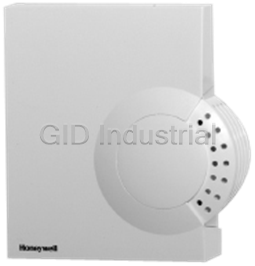
Description
Honeywell C7632B Carbon Dioxide Sensor and Controller, Duct Mount with One 0-10 Vdc Analog Output.
Part Number
C7632B
Price
Request Quote
Manufacturer
HONEYWELL
Lead Time
Request Quote
Category
Carbon Dioxide Sensor and Controller
Datasheet

Extracted Text
C7632A,B Sensor and Controller CARBON DIOXIDE SENSOR PRODUCT DATA FEATURES Non-Dispersion-Infrared (NDIR) technology used to measure carbon dioxide gas. Gold-plated sensor provides long-term calibration stability. Device provides voltage output based on CO levels. 2 Used for CO based ventilation control. 2 Automatic Background Calibration (ABC) algorithm based on long-term evaluation reduces required typical zero-drift check maintenance. Fixed 0 to 10 Vdc from 0 to 2000 ppm. No adjustments are necessary. C7632B Compatible with Honeywell Excel 10, 15, 5000, and any controller requiring 0-10 Vdc input. C7632A APPLICATION The C7632 Sensor and Controller is a stand-alone carbon dioxide (CO ) sensor for use in determining ventilation 2 necessity with heating ventilation and air conditioning (HVAC) controllers. The C7632 measures the CO concentration in 2 the ventilated space or duct. The C7632 is used in HVAC systems to control the amount of fresh outdoor air supplied to maintain acceptable levels of CO in the space. 2 SPECIFICATIONS Models: C7632 Sensor and Controller. A stand-alone carbon Electrical Ratings: dioxide (CO ) sensor with one 0-10 Vdc analog output. Power Supply: 24 Vac ±20%, 50/60 Hz (Class 2). 2 C7632A: Wall mount model. Maximum Power Consumption: C7632B: Duct mount model. Average: 1W. Peak: 2W. Dimensions: Peak Current (at 20 ms): 300 mA. C7632A: See Fig. 1. Linear Analog Output: 0-10 Vdc. C7632B: See Fig. 2. Mounting: Ambient Ratings: C7632A: Vertical surface with standard single-gang junction Temperature: box. Operating: +32°F to +122°F (0°C to +50°C). C7632B: Sheet metal duct with a sampling tube. Storage: -4°F to +158°F (-20°C to +70°C). Relative Humidity (non-condensing): 0 to 95 percent. CO Pressure Dependence: 1.6% change in reading per 2 1 kPa deviation from 100 kPa. Automatic Background Calibration (ABC) default: On. ® U.S. Registered Trademark Copyright © 2003 Honeywell International Inc. All Rights Reserved 63-2615 C7632A,B SENSOR AND CONTROLLER Output: Analog: 0-10 Vdc, 0-2000 ppm (fixed). INSTALLATION Sensor Performance Ratings: Response Time: 2 min. When Installing this Product... Carbon Dioxide Sensor: 1. Read these instructions carefully. Failure to follow them Operation: Non-dispersive infrared (NDIR). could damage the product or cause a hazardous Sampling: Diffusion. condition. Range: 0 to 2000 ppm (fixed). 2. Check the ratings given in the instructions and on the Annual Drift: ±10 ppm (nominal). product to make sure the product is suitable for your Accuracy: ±(30 ppm+2%) at normal temperature/pressure. application. Wiring Connections: 3. Installer must be a trained, experienced service C7632A: Terminal block. technician. C7632B: 20-gauge cable with three 6 in. leadwires. 4. After installation is complete, check out product operation as provided in these instructions. Approvals: CE. IMPORTANT Underwriters Laboratories Inc. Listed, File No. E4436. All wiring must agree with applicable codes, cUL. ordinances and regulations. C7632B: Flammability Rating, UL94-5V. C7632A: NEMA1. C7632B: NEMA3. CAUTION Health Hazard. Improper use can create dangerous situations. Use in application for sensing carbon dioxide only. For life-safety applications, this device can function 3-3/8 only as a secondary or lesser device. (86) 4-1/8 (104) CAUTION Electrical Shock or Equipment Damage Hazard. Can shock individuals or short equipment 2-11/16 (68) 1-1/16 circuitry. 3-7/8 (99) (27) M19794 Disconnect power supply before installation. Fig. 1. C7632A dimensions in in. (mm). CAUTION 3-5/16 (84) Equipment Damage Hazard. 1-13/16 (46) Electrostatic discharge can short equipment circuitry. Ensure that you are properly grounded before 5-5/8 (142) handling the unit. C7632A Cover Removal/Replacement 1-5/8 8 (203) (41) The cover of the C7632A is fixed by a latch on the underside M19795 of the unit. Fig. 2. C7632B dimensions in in. (mm). ORDERING INFORMATION When purchasing replacement and modernization products from your TRADELINE® wholesaler or distributor, refer to the TRADELINE® Catalog or price sheets for complete ordering number. If you have additional questions, need further information, or would like to comment on our products or services, please write or phone: 1. Your local Honeywell Automation and Control Products Sales Office (check white pages of your phone directory). 2. Honeywell Customer Care 1885 Douglas Drive North Minneapolis, Minnesota 55422-4386 In CanadaHoneywell Limited/Honeywell Limitée, 35 Dynamic Drive, Scarborough, Ontario M1V 4Z9. International Sales and Service Offices in all principal cities of the world. Manufacturing in Australia, Canada, Finland, France, Germany, Japan, Mexico, Netherlands, Spain, Taiwan, United Kingdom, U.S.A. 63-2615 2 C7632A,B SENSOR AND CONTROLLER 2. Insert tube into duct; attach using screws and washers. C7632A Cover Removal (see Fig. 3) 1. Unless the device is mounted, hold the base using the IMPORTANT wiring hole and/or the perforated vent. Leakage into the duct or the C7632 box cover from 2. Depress the tab on the underside of the device. the room will skew the sensor readings. Ensure the 3. Swing the cover away from the base. box cover and duct seal completely. 4. Lift cover from base. 3. Place o-ring on tube end; mount the control to the tube. C7632A Cover Replacement 1. Place top cover tab over the ridge along the base top. 2. Swing the cover down. 3. Press the lower edge of the case to latch. Location and Mounting C7632 Sensors mount directly on the wall, sheet metal duct, or a panel. When planning the installation, allow enough clearance for maintenance and service. Mount the sensor in a well-ventilated area. NOTES: Do not install the sensor where it can be affected by: drafts or dead spots behind doors and in corners. M19797 air from ducts. Fig. 4. Junction box mounting (C7632A). M19796 Fig. 3. C7632A cover removal. Wall Mounting (C7232A) Mount the C7232A to the wall as follows: M19798 1. Remove the C7632 cover. 2. Mount the device in a vertical position. Fig. 5. Duct mounting (C7632B). 3. Mount the subbase directly on a wall using the type of screws (not supplied) appropriate for the wall material. 4. Replace the cover. WIRING (FIG. 6) Junction Box Mounting (Fig. 4) Mount the C7232A to a junction box as follows: 1. Attach the wallplate using only the top screw. CAUTION 2. Remove the C7632 cover. Electrical Shock or Equipment Damage Hazard. 3. Place the subbase on the wallplate hook. Can shock individuals or short equipment 4. Mount the subbase and wallplate to the junction box circuitry. using the lower screw. Disconnect power supply before installation. 5. Replace the cover. Duct Mounting (see Fig. 5) CAUTION 1. Place gasket on aspiration tube. Equipment Damage Hazard. Electrostatic Discharge Can Short Equipment IMPORTANT Circuitry. Ensure largest tab at tube control end is at the top. Ensure that you are properly grounded before handling the unit. 3 63-2615 FLOW C7632A,B SENSOR AND CONTROLLER IMPORTANT 3. Execute calibration by shorting the proper two soldering 1. All low voltage connections to this device must be pads (see Fig. 7). 24 Vac Class 2. NOTE: The device should now provide accurate output. 2. All wiring must comply with applicable local codes, ordinances and regulations. 4. Check the output signal. (See Checkout section.) 5. Reinstall the device. Table 1. C7632 Wiring Connections (see Fig. 6). Designation C7632B Wire Color Function Background Calibration G+ Red 24 Vac 1. Remove the sensor cover and set it aside. G0 Black Common 2. Ventilate the area and reduce occupancy to lower the CO levels. CO Brown Analog Output Signal 2 2 3. Maintain a reasonable proximity from the sensor to avoid breathing on it, thus skewing calibration accuracy. C7632 4. Keep the sensor in this environment for three to four L1 (HOT) minutes. L2 5. Execute calibration by shorting the proper two soldering 1 G0 CO G+ 2 pads (see Fig. 7). 0-10 Vdc NOTE: The device should now provide accurate output. 1 POWER SUPPLY. PROVIDE DISCONNECT MEANS AND 6. Check the output signal. (See Checkout section.) OVERLOAD PROTECTION AS REQUIRED. M19799 7. Reinstall the device. Fig. 6. Wiring the C7632. ZERO BACKGROUND CALIBRATION CALIBRATION Output (Table 2) Table 2. 0-10 Vdc Output Signal. CO2 0 200 400 600 800 1000 1200 1400 1600 1800 2000 Level (ppm) Voltage 0 1 2 3 4 5678910 M19856 Output (Vdc) Fig. 7. C7632 calibration pads. CALIBRATION CHECKOUT Typically, calibration is unnecessary. No calibration kits are Perform a quick test of the unit with the unit powered: available. However, if CO levels can be brought to a 1. After calibration: 2 desirable level, the sensor can be reset using either zero or a. Check output signal immediately following proper background calibration: calibration (with minimum environmental change): (1) Proper zero calibration: 0 Vdc. IMPORTANT (2) Typical background calibration: 2 Vdc. Depending With zero calibration, all CO present during on ambient CO level, range: 1.75 to 2.5 Vdc. 2 2 calibration skews the sensor zero level. b. If the output is incorrect, repeat calibration Using background calibration, practical operation procedure. (with a higher than zero level set) can be obtained. c. Otherwise, continue with checkout. 2. Stand close to the unit and breathe air into the sensor. Zero Calibration NOTE: When connected to a damper in a ventilation 1. Remove the sensor cover and set it aside. system, breathing on the sensor typically 2. Apply a steady flow of CO -free gas at 0.1 to 0.5 liter per 2 signals an increase in air flow. minute into the gas inlet tube located on the gold sensor. 3. Check the output to ensure a strong rise in CO level. 2 Automation and Control Solutions Honeywell International Honeywell Europe S.A. Honeywell Latin American Honeywell International Inc. Honeywell Limited-Honeywell Limitée Control Products 3 Avenue du Bourget Region 1985 Douglas Drive North 35 Dynamic Drive Honeywell Building 1140 Brussels 480 Sawgrass Corporate Parkway Golden Valley, MN 55422 Scarborough, Ontario 17 Changi Business Park Central 1 Belgium Suite 200 M1V 4Z9 Singapore 486073 Sunrise FL 33325 Printed in U.S.A. on recycled 63-2615 B.B. 11-03 www.honeywell.com paper containing at least 10% post-consumer paper fibers.
Frequently asked questions
How does Industrial Trading differ from its competitors?

Is there a warranty for the C7632B?
Which carrier will Industrial Trading use to ship my parts?
Can I buy parts from Industrial Trading if I am outside the USA?
Which payment methods does Industrial Trading accept?


What they say about us
FANTASTIC RESOURCE
One of our top priorities is maintaining our business with precision, and we are constantly looking for affiliates that can help us achieve our goal. With the aid of GID Industrial, our obsolete product management has never been more efficient. They have been a great resource to our company, and have quickly become a go-to supplier on our list!
Bucher Emhart Glass
EXCELLENT SERVICE
With our strict fundamentals and high expectations, we were surprised when we came across GID Industrial and their competitive pricing. When we approached them with our issue, they were incredibly confident in being able to provide us with a seamless solution at the best price for us. GID Industrial quickly understood our needs and provided us with excellent service, as well as fully tested product to ensure what we received would be the right fit for our company.
Fuji
HARD TO FIND A BETTER PROVIDER
Our company provides services to aid in the manufacture of technological products, such as semiconductors and flat panel displays, and often searching for distributors of obsolete product we require can waste time and money. Finding GID Industrial proved to be a great asset to our company, with cost effective solutions and superior knowledge on all of their materials, it’d be hard to find a better provider of obsolete or hard to find products.
Applied Materials
CONSISTENTLY DELIVERS QUALITY SOLUTIONS
Over the years, the equipment used in our company becomes discontinued, but they’re still of great use to us and our customers. Once these products are no longer available through the manufacturer, finding a reliable, quick supplier is a necessity, and luckily for us, GID Industrial has provided the most trustworthy, quality solutions to our obsolete component needs.
Nidec Vamco
TERRIFIC RESOURCE
This company has been a terrific help to us (I work for Trican Well Service) in sourcing the Micron Ram Memory we needed for our Siemens computers. Great service! And great pricing! I know when the product is shipping and when it will arrive, all the way through the ordering process.
Trican Well Service
GO TO SOURCE
When I can't find an obsolete part, I first call GID and they'll come up with my parts every time. Great customer service and follow up as well. Scott emails me from time to time to touch base and see if we're having trouble finding something.....which is often with our 25 yr old equipment.
ConAgra Foods