

 Manufacturers
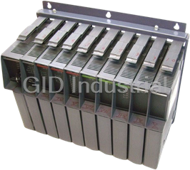
GIDDINGS & LEWIS PiC900
Description
PIC 900 Programmable Industrial Controller
Part Number
PiC900
Price
Request Quote
Manufacturer
GIDDINGS & LEWIS
Lead Time
Request Quote
Category
Systems
Features
- Contains a data bus, address bus and control lines. These lines allow data to pass between the CPU (or CSM/CPU) module and each of the other modules.
- It has a 64-pin female connector at each slot position which allows communication between modules.
- Passes power from the CSM (or CSM/CPU)to each of the other modules.
- Provides physical support for the top and bottom of each hardware module.
Datasheet

Extracted Text
PiC900 CONTROLS MOTION SOLUTIONS PRODUCT GUIDE Part Number M.1301.4204 Version 1.0 Giddings & Lewis PiC900 Controls NOTE Progress is an ongoing commitment at Giddings & Lewis. We continually strive to offer the most advanced products in the industry; therefore, information in this document is subject to change without notice. The illustrations and specifications are not binding in detail. Giddings & Lewis shall not be liable for any technical or editorial omissions occurring in this document, nor for any consequential or incidental damages resulting from the use of this document. DO NOT ATTEMPT to use any Giddings & Lewis product until the use of such product is completely understood. It is the responsibility of the user to make certain proper operation practices are understood. Giddings & Lewis products should be used only by qualified personnel and for the express purpose for which said products were designed. Should information not covered in this document be required, contact the Customer Service Department, Giddings & Lewis, 660 South Military Road, P.O. Box 1658, Fond du Lac, WI 54936- 1658. Giddings & Lewis can be reached by telephone at 920 921 7100. Version 1.0 Copyright © 1999 - 2002 Giddings & Lewis, LLC ARCnet is a trademark of Datapoint Balluff is a trademark of Gerhard Balluff Febrick Feinmechanischer Erzeugnisse GMBH & Co. Belden is a trademark of Cooper Industries, Inc. Cimplicity is a trademark of GE FanucAutomation North America, Inc. Cimrex is a trademark of Cimrex Electronic AB Data Highway Plus is a trademark of Allen-Bradley Company DeviceNet is a trademark of Iris Technologies, Inc. IBM is a trademark of International Business Machines Corp. IEEE is a trademark of the Institute of Electrical and Electronics Engineers Inductosyn is a trademark of Ruhle Companies Inc.., Farrand Optical Co., Inc. Intellution is a trademark of Intellution, Inc. Modbus is a trademark of Gould, Inc. MODHUB is a trademark of CCSi Modicon is a trademark of Modicon Corporation NEMA is a trademark of the National Energy Manufacturers Association OPC OLE for Process Control is a trademark of OPC Foundation Pentium is a trademark of Intel Corporation RSView is a trademark of Rockwell Software, Inc. Temposonics is a trademark of MTS Systems Corporation Windows 95, Windows 98, Windows NT, MS-DOS, QuickBASIC, and Microsoft are trademarks of Microsoft Corporation Wonderware is a trademark of Wonderware Corporation PiC900, PiC90, PiCPro, PiCServoPro, PiCMicroTerm, Centurion, and MMC are trademarks of Giddings & Lewis, LLC Table of Contents: PiC900 Controls Product Guide Introduction .................................................................................................................... 1 The PiC™ System ...................................................................................................... 3 System Racks ............................................................................................................. 5 PiC Family CSM/ RSM Modules ................................................................................. 9 CSM Module/RSM Module ....................................................................................... 11 PiC90 RSM I/O Module ............................................................................................ 15 Specification Table .......................................................................................... 16 PiC Family CPU Modules ............................................................................................. 17 PiC94X CPU Module ................................................................................................ 19 Specification Table ......................................................................................... 20 PiC904X- CSM/CPU Central Service Module/Central Processing Unit .................. 24 Specification Table ........................................................................................... 25 PiC 900 Communications Modules .............................................................................. 29 Ethernet - TCP/IP Module ......................................................................................... 31 Specification Table ......................................................................................... 32 DeviceNet Module ..................................................................................................... 34 Specification Table ........................................................................................... 35 Serial Communications Module (2, 4 channel) ......................................................... 36 Specification Table ........................................................................................... 37 I/O Expansion ............................................................................................................ 39 Block I/O Expansion .................................................................................................. 41 PiC 900 Discrete I/O Modules ....................................................................................... 43 Input 24V DC Module (32 or 16 points) ................................................................... 45 Specification Table ........................................................................................... 46 Input 24V DC Module (16 switch) ............................................................................ 48 Specification Table ................................................................................... 49 Input 12V DC Module (32 points) ............................................................................. 51 Specification Table ........................................................................................... 52 Input 120V AC Module (16 points) ........................................................................... 54 Specification Table ........................................................................................... 55 Output 24V DC Source Module (32 or 16 points) ..................................................... 57 Specification Table .......................................................................................... 58 Output 24V DC Sink Module (3 versions) ................................................................ 60 Specification Table .......................................................................................... 61 Output Relay Module (8 points) ................................................................................ 63 Specification Table ........................................................................................... 64 Output 120/240V AC Module (32 or 16 points) ........................................................ 66 Specification Table ........................................................................................... 67 Input/Output TTL Module (24 inputs/8 outputs) ....................................................... 69 Specification Table ........................................................................................... 70 Input/Output 24V DC Sink Module (16/8 points) ..................................................... 72 Specification Table ........................................................................................... 73 Giddings & Lewis PiC900 Controls Motion Solutions Product Guide -i Input/Output 24V DC Source Module (16/8 points) ................................................. 75 Specification Table ........................................................................................... 76 PiC 900 Analog Modules ............................................................................................... 79 Analog Input Module (8 channel) .............................................................................. 81 Specification Table .......................................................................................... 82 Analog Output ±10V DC Module (8, 4 channel) ...................................................... 85 Specification Table ........................................................................................... 86 Analog Input ±10V Output (4 Channel) .................................................................... 89 Specification Table ........................................................................................... 90 TEMP J-K Thermocouple Module (12 channel) ....................................................... 93 Specification Table ........................................................................................... 94 RTD Module (6 channel) ........................................................................................... 97 Specification Table ........................................................................................... 98 Output 4-20mA Module (6 channel) ......................................................................... 101 Specification Table ........................................................................................... 102 PiC Family Miscellaneous Modules ............................................................................. 105 Barrier Module ........................................................................................................... 107 PiC 900 Servo/Feedback Modules ................................................................................ 109 Encoder Module (2, 4, High Speed 4 channel) .......................................................... 111 Specification table ............................................................................................. 112 Resolver Module (4, 2 channel) ................................................................................. 115 Specification Table ........................................................................................... 116 Multi-Channel Resolver Module (12 channel) .......................................................... 119 Specification Table ........................................................................................... 120 Servo Encoder with Analog I/O Module ................................................................... 122 Specification Table ........................................................................................... 123 Servo Encoder with Analog Output Module ............................................................. 126 Specification Table ........................................................................................... 127 Slider Driver Module ................................................................................................. 130 Specification Table ......................................................................................... 131 Output Stepper Module (8 channel) ........................................................................... 132 Specification Table .......................................................................................... 133 Output Stepper Axis Module (8 channel) .................................................................. 135 Specification Table .......................................................................................... 136 SERCOS Module for PiC .......................................................................................... 138 Specification Table ........................................................................................... 139 Specification Table for the Fiber Optic Cable .................................................. 140 PiC 900 Options and Accessories ................................................................................. 141 I/O Wiring Harness .................................................................................................... 143 Battery Backup Board ................................................................................................ 145 -ii PiC900 Controls Motion Solutions Product Guide Giddings & Lewis PiC900 CONTROLS MOTION SOLUTIONS PRODUCT GUIDE Introduction Giddings & Lewis The PiC™ System The PiC™ System The PiC is more than just a motion control. It’s a machine control. The PiC combines motion, logic, and process control all in a single programming environment. Programmed with IEC1131 ladder logic and function block language using our powerful PiCPro for Win- dows software, the PiC provides a close coupled, integrated solution to the logic, motion, pro- cess, operator interface, and communications requirements found in today’s industrial automation applications. A PiC system consists of the components found in the following illustration. Motion control is accomplished through the use of encoder/resolver feedback modules and analog output modules, or by using the SERCOS module. The machine inputs and outputs (logic and pro- cess control) are handled with a wide variety of rack I/O or distributed block I/O modules. All I/O modules can be used across the PiC90 and PiC900 product lines interchangeably. Serial communications modules and application-specific software functions allow the PiC to com- municate to a wide variety of operator interface devices. PiCPro is the machine control software that ties it all together. Application programs devel- oped for any PiC solution are 100% software compatible with one another. Motion, logic, operator interface, and process control are all performed in a single programming environ- ment, simplifying development, maintenance, and troubleshooting of the application program. Generally throughout this guide, the PiC refers to the PiC family of Programmable industrial Computers and includes the PiC90. Giddings & Lewis PiC900 Controls Motion Solutions Product Guide 3 The PiC™ System PiC System 2 PICPro 3 PICServoPro User provided Personal Computer for Program Development Machine Inputs/Outputs PiC900 or 1 PIC900 PiC90 Machine Servos/ 4 Feedback Devices Position Loop 5 Motor Drive Operator Interface Devices (optional) 1 PiC900/90 The PiC900/90 is comprised of a system rack, a CSM module and a CPU module for the PiC900 or a CSM/CPU module for the PiC90, and I/O modules. System rack - available in 7, 10, or 13 slots for the PiC900 and 3 or 5 slots for the PiC90. 2 PiCPro for Windows Software and Workstation The software and computer which are used to develop application programs. 3 Machine Inputs/Outputs The physical inputs to and outputs from the machine(s) that are controlled by the PiC. 4 Position Loop The physical elements that provide closed loop control over axial positions - the feedback device(s) of the machines and the analog output module of the PiC. 5 Operator Interface Devices A terminal, touch screen, or PC which can optionally be used by operators to interface with the system. 4 PiC900 Controls Motion Solutions Product Guide Giddings & Lewis System Racks System Racks The system rack has four functions: 1. It provides physical support for the top and bottom of each hardware module. 2. It passes power from the CSM (or CSM/CPU) to each of the other modules. 3. It contains a data bus, address bus and control lines. These lines allow data to pass between the CPU (or CSM/CPU) module and each of the other modules. 4. It has a 64-pin female connector at each slot position which allows communication between modules. Dimensions of the racks PiC system racks differ only in length and the number of hardware modules they can contain. A dimensional diagram of each rack is shown on the following pages. System Racks Number of Number of Depth Part Number actual slots modules Length Height (with modules) PiC900 13 CSM, CPU, 21.6" 14.0" 9.0" M.1017.1606 11 I/O (old # 503-18011-03) 10 CSM, CPU, 8 16.8" 14.0" 9.0" M.1017.1600) I/O (old # 503-18010-03) 7 CSM, CPU, 5 12.0" 14.0" 9.0" (M.1017.1594 I/O (old # 503-18009-03) PiC90 5* CSM/CPU, 4 8.8" 14.0" 9.0" M.1017.2284 I/O (old # 503-19184-02) 3* CSM/CPU, 2 5.6" 14.0" 9.0" M.1017.2288 I/O (old # 503-19185-02) *The PiC90 retaining bar labels the CSM/CPU module slot as 1/2, leaving 2 or 4 slots avail- able for I/O modules. In the illustrations that follow, racks with 3, 5, and 7 slots are shown with modules inserted. All racks are the same height and have the same profile. The next two rack sizes are shown empty. Giddings & Lewis PiC900 Controls Motion Solutions Product Guide 5 System Racks System Racks with Modules Installed PiC90 Slots 3 and 4 available PiC90 for hardware modules Slots 3, 4, 5, and 6 available for hardware modules .365 "/9.3 mm .365 "/9.3 mm 2.8" 71 mm 1/2 3 4 1/2 3 456 CSM/CPU I/O I/O Servo Servo CSM/CPU I/O I/O 2.3" 6"/152mm .265 "/6.7mm .265 "/6.7mm 58.4 mm 1.4"/35.6 mm 8.8"/224mm 1.4"/35.6 mm 5.6"/142mm PiC900 .365 "/9.3 mm Slots 3, 4, 5, 6, and 7 available for hardware modules CSM CPU I/O I/O I/O I/O I/O Side View All racks 9.2" / 234mm 9.0" / 229mm .265 "/6.7mm 1.4"/35.6 mm 12.0" / 305mm 6 PiC900 Controls Motion Solutions Product Guide Giddings & Lewis 14.0”/355mm 14.0”/355mm 13.375”/240mm 13.375”/340mm 14.0”/355mm 13.375”/340mm System Racks The 10-slot System Rack .365 "/9.3 mm 7.0" / 178mm .265 "/6.7mm 14.0" / 356mm 1.4"/35.6 mm 16.8" / 427mm The 13-slot System Rack .365 "/9.3 mm 9.4" / 239mm .265 "/6.7mm 18.8" / 478mm 1.4"/35.6 mm 21.6" / 549mm Giddings & Lewis PiC900 Controls Motion Solutions Product Guide 7 14.0”/355mm 13.375”/340mm 14.0”/355mm 13.375”/340mm System Racks 8 PiC900 Controls Motion Solutions Product Guide Giddings & Lewis PiC900 CONTROLS MOTION SOLUTIONS PRODUCT GUIDE PiC Family CSM/ RSM Modules Giddings & Lewis CSM Module/RSM Module CSM Module/RSM Module The Central Service Module (CSM) and the Remote Service Module (RSM) convert incom- ing power to regulated DC power. Through the bus, the CSM supplies this power to the mod- ules in the master rack and the RSM supplies this power to the modules in an expansion rack. The CSM has the following additional features: • Scan control which includes a key switch to run/stop the scan when power is on. A lithium battery to back up such items as non-volatile RAM in the CPU module and the time-of-day clock on the CSM module when power is turned off. An internal clock to provide time of day and date when needed by the software. The CSM and the RSM must always be located in the first slot on the left in the master rack and expansion rack respectively. CSM - the Central Service Module (for master RSM - the Remote Service Module (for rack) expansion rack) Name of Module Name of Module CSM RSM DIAG DIAG PWR PWR LEDs LEDs SCAN SCAN BATT BATT (not used) Key slot Key slot Run Run Stop Stop Door Door ON ON Power switch Power switch OFF OFF L/LINE1 L/LINE1 Power connector Power connector N/LINE2 N/LINE2 E/GRND E/GRND Giddings & Lewis PiC900 Controls Motion Solutions Product Guide 11 CSM Module/RSM Module Specification Table Characteristic CSM/RSM specifications Functions Supplies regulated DC power to the hardware modules installed in the rack AC power source 110-230 VAC, 47-63 Hz, 2 A Model Part Number CSM-50 M.1016.8879 (old # 502-03512-03) CSM-60 M.1016.9294 (old # 502-03813-03) RSM-50 M.1016.9243 (old # 502-03732-03) RSM-60 M.1016.9308 (old # 502-03817-03) DC power source 20 - 60 VDC, 3 A Model Part Number CSM-50 M.1016.9475 (old # 502-03973-00) (24 VDC) Input connector 3-terminal plug connector, meets all specifications for touch safety in accordance with IEC 529 and DIN VDE 0470 part 1 Power output, total Model Power CSM/RSM-50 50 W CSM/RSM-60 60 W CSM 24 VDC 50 W Individual outputs +5 V @ 4.0 A +5 V @ 8.5 A +5 V @ 4.0 A +15 V @ 2.0 A +15 V @ 1.5 A + 15 V @ 1.0 A -15 V @ .5 A -15 V @ 1.5 A -15 V @ .5 A 12 PiC900 Controls Motion Solutions Product Guide Giddings & Lewis CSM Module/RSM Module Battery (CSM only) 1.2 Ah 3 V, 2/3 A lithium battery Part number M.1015.9316 (old # 401-52446-00) + 5 V supply monitor Trip points ± 5% ± .5%: 4.725 to 4.775 V and 5.225 to 5.275 V PWR LED goes off and PiC shuts down ± 15 V supply monitor Trip points ± 8% ± 2%: 13.5 to 14.1 V and 15.9 to 16.5 V Time-of-day clock (CSM only) Access via PiCPro or application program. Clock tolerance (CSM only) At 25°C, ±1 second per day Over temperature, voltage and aging variation, +2/-12 seconds per day Logic side power requirements (typical) 25 mA @ +5 V 2 mA @ +15 V 2 mA @ - 15 V 2 µA @ +3 V (from battery during power down on CSM) Operating temperature range 7°C to 55°C (45°F to 131°F) Storage temperature range -40°C to 85°C (-40°F to 185°F) Humidity 5 to 95%, non-condensing EMC Compliant Refer to the EMC Guidelines for more information. Emissions Operates with emissions below EN55011/ CISPR 11 Class A limits Noise immunity Immune to: Electrostatic discharge (4K V contact mode, 8K V air discharge) per IEC 1000-4-2 RF electromagnetic fields per IEC 1000-4-3 Electrical fast transients per IEC 1000-4-4 on incoming power lines Giddings & Lewis PiC900 Controls Motion Solutions Product Guide 13 CSM Module/RSM Module CE Marked Conforms to Directives 73/23/EEC, 89/336/EEC, 92/31/ EEC, 93/68/EEC by conforming to the following stan- dards: EN 50081-2:1993 EMC Generic Industrial Emissions EN 50082-2:1995 EMC Generic Industrial Immunity EN 61131-2:1994/A11:1996 Low voltage directive require- ments for programmable controllers Operates with emissions below EN5501/CISPR 11 Class A limits Immune to: Electrostatic discharge (4K V contact mode, 8K V air discharge) per EN61000-4-2 RF electromagnetic fields per EN61100-4-3, ENV50141, and ENV50204 UL and C/UL Listed File No. E126417 NRAQ Programmable Controllers (CSM/RSM-50) Physical size 2.4" wide x 12" high x 8.4" deep (including latch) 61 mm x 305 mm x 213 mm Vibration (per IEC 68-2-7) 10-57 Hz (constant amplitude .15 mm) 57-2000Hz (acceleration 2 g Shock (per IEC 68-2-27) Four shocks per axis (15g/11 msec) 14 PiC900 Controls Motion Solutions Product Guide Giddings & Lewis PiC90 RSM I/O Module PiC90 RSM I/O Module When a PiC90 3- or 5-slot rack is used as a remote or local expansion rack for a PiC900 mas- ter rack, an RSM I/O driver module is required in slot 1/2 of the PiC90 rack. The RSM I/O driver module converts AC power to regulated DC power. Through the bus, the RSM supplies this power to the modules in an expansion rack. A PiC900 system may include up to eight expansion racks containing I/O modules. The RSM I/O driver module must be installed in each PiC90 3- or 5-slot expansion rack and an RSM module and an I/O driver module must be installed in each PiC900 7-, 10-, or 13-slot expan- sion rack. The DIAG LED turns on briefly while the diagnostic tests are running. RSM I/O - the Remote Service Module I/O Driver (for 3- or 5- slot PiC90 expansion rack) RSM I/O Name of Module DIAG PWRSCAN LEDs CONFIG DATA IN/OUT (Key slot not used) Run Stop ON Power switch OFF L/LINE1 N/LINE2 Power connector E/GRND I/O local expansion twisted pair out I/O local expansion twisted pair in Door In Out Fiber optic connections Giddings & Lewis PiC900 Controls Motion Solutions Product Guide 15 PiC90 RSM I/O Module Specification Table Characteristic RSM I/O driver specifications Functions Supplies regulated DC power to hardware modules installed in the rack and allows additional racks of I/O modules to be connected to a PiC900 master rack Part number M.1016.9385 (old # 502-03876-02) AC power source 120-230 V AC, 47-63 Hz Input connector 3-terminal plug connector, meets all specifications for touch safety in accordance with IEC 529 and DIN VDE 0470 part 1 Power output, total 40 W Individual outputs + 5 V @ 5.0 A + 15 V @ 2.0 A -15 V @ .5 A + 5 V supply monitor Trip points ± 5% ± .5%: 4.725 to 4.775V and 5.225 to 5.275 V PWR LED goes off and PiC900 shuts down Logic side power requirements 510 mA @ +5V (typical) Operating temperature range 7° C to 55° C (45° F to 131° F) Storage temperature range -40° C to 85° C (-40° F to 185° F) Humidity 5 to 95%, non-condensing EMC Compliant Refer to the EMC Guidelines for more information. Emissions Operates with emissions below EN55011/ CISPR 11Class A limits Noise immunity Immune to: Electrostatic discharge (4K V contact mode, 8K V air discharge) per IEC 1000-4-2 RF electromagnetic fields per IEC 1000-4-3 Electrical fast transients per IEC 1000-4-4 on incoming power lines UL and C/UL Listed File No. E126417 NRAQ Programmable Controllers Physical size 2.4" wide x 12" high x 8.4" deep (including latch) 61 mm x 305 mm x 213 mm Vibration (per IEC 68-2-6) 10-57 Hz (constant amplitude .15 mm) 57-2000 Hz (acceleration 2 g) Shock (per IEC 68-2-27) Four shocks per axis (15g/11msec) 16 PiC900 Controls Motion Solutions Product Guide Giddings & Lewis MOTION SOLUTIONS PRODUCT GUIDE PiC Family CPU Modules Giddings & Lewis PiC94X CPU Module PiC94X CPU Module The PiC94X Turbo CPU module controls the PiC900 system and executes the application pro- gram. It contains: A processor IC providing overall control A math coprocessor Eight LEDs RAM (EPROM optional) memory for the application program and for RAMDISK RAM memory for data storage as the system runs FLASH memory for the system software RS232 ports to communicate with the computer workstation and with a serial interface device Optional communication (ARCNET, I/O, and Block I/O expansion) capability Optional flash memory for storing things like application source modules The CPU module must always be in the second slot from the left in the system rack. PiC94X Turbo CPU Module CPU Name of Module Diagnostic LED I/O Driver LEDs ARCNET LEDs User Port LEDs TURBO PiC900 Communications RS232 port, to computer workstation RS232 User Port, to serial interface device Fiber Optic Connections Giddings & Lewis PiC900 Controls Motion Solutions Product Guide 19 PiC94X CPU Module Specification Table Characterisitcs CPU 94X module specifications Function Executes the application program. Executes Diagnostics on the system and it’s modules. Communicates through RS232 port to external devices. Can provide ARCNET and I/O expansion from module. Number of servo axes available at five CPUs update rates ** App RAM User 8 4 2 1 .5 Model CPU Part Number Speed Mem Mem Mem ms ms ms ms ms 941 80486DX2 M.1016.9626 16 MHz 512K 256K 64K 16 8 4 2 1 (old # 502-04111-01) 2 80486DX2 M.1016.9627 16 MHz 512K 256K 64K 16 8 4 2 1 Turbo (old # 502-04111-11)* 943 80486DX2 M.1016.9508) 32 MHz 512K 256K 64K 32 16 8 4 2 (old # 502-04011-01) 2 80486DX2 M.1016.9510 32 MHz 512K 256K 64K 32 16 8 4 2 Turbo (old # 502-04011-11)* 945 3 80486DX2 M.1016.9491 50 MHz 512K 256K 64K 32 32 16 8 4 Turbo (old # 502-03994-11)* 947 80486DX4 M.1016.9629 100MHz 512K 256K 64K 32 32 24 12 8 3 Turbo (old # 502-04112-11)* *ARCNET and I/O expansion communications are standard on these modules. **The number of axes listed is typical for RATIO_GR, RATIOCAM, VEL_STRT, POSITION and DISTANCE move types. Applications which use time axes, servo tasks, RATIO_RL, M_LINCIR, or M_SCRVLC moves require more CPU time. Consult Giddings & Lewis for assistance if you want to exceed the number of axes in this chart. 20 PiC900 Controls Motion Solutions Product Guide Giddings & Lewis PiC94X CPU Module Flash memory system board 8 Megabyte FMS Board (optional) M.1016.9390 (old # 502-03882-20) Memory 1 Megabyte max. PiCPro Port (to workstation) RS232 serial port, secured protocol Software selectable baud rate to 115.2K User Port (to serial interface RS232 serial port device) Supports RTS/CTS hardware handshaking Software selectable baud rate to 19.2K Part Number +5 V + 15 V -15 V Logic side power requirements (typical) M.1016.9626 700 mA 4 mA 10 mA (old # 502-04111-01) M.1016.9508 800 mA 4 mA 10 mA (old # 502-04011-01) M.1016.9627 900 mA 4 mA 39 mA (old # 502-04111-11)* M.1016.9510 1000 mA 4 mA 39 mA (old # 502-04011-11)* M.1016.9491 1400 mA 4 mA 39 mA (old # 502-03994-11)* M.1016.9629 1100 mA 4 mA 39 mA (old # 502-04112-11)* All CPUs draw 15 µA from the battery during power down. * CPUs with ARCNET and I/O capabilities on board. Operating temperature range 7°C to 55°C (45°F to 131°F) Storage temperature range -40°C to 85°C (-40°F to 185°F) Humidity 0 to 95%, non-condensing Giddings & Lewis PiC900 Controls Motion Solutions Product Guide 21 PiC94X CPU Module EMC Compliant Emissions Operates with emissions below EN55011/ CISPR 11 Class A limits Noise immunity Immune to: Electrostatic discharge (4K V contact mode, 8K V air discharge) per IEC1000-4-2 RF electromagnetic fields per IEC 1000-4-3 Electrical fast transients per IEC 1000-4-4 on incom- ing power lines Refer to the EMC Guidelines for more information. UL and C/UL Listed File No. E126417 NRAQ Programmable Controllers Physical size 1.6" wide x 12" high x 8.4" deep (including latch) 41 mm x 305 mm x 213 mm Vibration (per IEC 68-2-6) 10-57 Hz (constant amplitude .15mm) 57-2000 Hz (acceleration 2g) Shock (per IEC 68-2-27) Four shocks per axis (15g/11 msec) 22 PiC900 Controls Motion Solutions Product Guide Giddings & Lewis PiC94X CPU Module NOTES Giddings & Lewis PiC900 Controls Motion Solutions Product Guide 23 PiC904X- CSM/CPU Central Service Module/Central Processing Unit PiC904X- CSM/CPU Central Service Module/Central Processing Unit The PiC9041 or 9043 CSM/CPU module occupies the 1/2 slot in the rack. The CSM/CPU converts AC or DC power to regulated DC power. It supplies this power to the modules in the rack through the bus. The CSM/CPU controls the PiC90 system and executes the application program. PiC904X CSM/CPU Module Name of Module CSM/CPU SCAN/BAT/PWR/DIAG PROG/USER PORTS LEDs ARCNET CONFIG BLOCK I/O Run Key slot Stop ON Power switch OFF L/LINE1 N/LINE2 Power connector E/GRND RS232 port, connector to PiCPro computer workstation P-P and User Block I/O Port RS232 port, connector (to user serial interface) Door Peer-to-Peer communication port or block I/O (optional) 24 PiC900 Controls Motion Solutions Product Guide Giddings & Lewis PiC904X- CSM/CPU Central Service Module/ Central Processing Unit Specification Table Characterisitcs CSM/CPU specifications Functions Supplies regulated DC power to the hardware modules installed in the rack. Executes the application program. Executes Diagnostics on the system and it’s modules. Communicates through RS232 port to external devices. Peer -to-peer communications with PiC family of controls (optional). Number of servo axes available at six update Models available rates * PiC90 Model (with AC Power App RAM User 8 4 2 1 .5 .25 Part Number Speed Source) Mem Mem Mem ms ms ms ms ms ms 9041 Standard w/o M.1016.9615 16 256K 128K 64K 12 6 4 2 1 0 comm MHz (old # 502-04104-01) 9041 Standard w/ M.1016.9617 16 256K 128K 64K 12 6 4 2 1 0 comm (old # 502-04104-11) MHz 9043 Turbo w/o M.1016.9677) 32 256K 128K 64K 12 12 8 4 2 1 comm (old # 502-04125-01) MHz 9043 Turbo w/ comm M.1016.9679 32 256K 128K 64K 12 12 8 4 2 1 (old # 502-04125-11) MHz PiC90 Model (with DC Power Source) 9043Turbo w/ comm M.1016.9682 32 256K 128K 64K 12 12 8 4 2 1 (old # 502-04126-10) MHz *The number of axes listed is typical for RATIO_GR, RATIOCAM, VEL_STRT, POSITION and DISTANCE move types. Applications which use time axes, servo tasks, RATIO_RL, M_LINCIR, or M_SCRVLC moves require more CPU time. Consult Giddings & Lewis for assistance if you want to exceed the number of axes in this chart. Giddings & Lewis PiC900 Controls Motion Solutions Product Guide 25 PiC904X- CSM/CPU Central Service Module/Central Processing Unit AC power source 110-230 V AC, 47-63 Hz, 1A DC power source 20 -30V DC, 3 A Input connector 3-terminal plug connector, meets all specifications for touch safety in accordance with IEC 529 and DIN VDE 0470 part 1 CSM/CPU Power output, total 40 W (for AC power source) 30 W (for DC power source) Individual outputs AC Power Source DC Power Source + 5V @ 5.0 A 3 A + 15V @ 2.0 A 1 A -15V @ .5 A .5 A Battery 1.2 Ah 3V, 2/3A lithium battery + 5 V supply monitor Low trip point 4.50V min 4.75V max High trip point 5.50V min 5.94V max PWR LED goes off and PiC9041 shuts down Flash memory system 8 Megabyte FMS Board M.1016.9390 (old # 502-03882-20) board (optional) PiCPro port Used to connect to the work station RS232 serial port, secured protocol Software selectable baud rate (300 to 57600 baud) User port Used to connect to a serial interface device RS232 serial port Supports RTS/CTS hardware handshaking Baud rates to 19.2 K Peer-to-peer communica- Allows for communication between PiC90s and/or PiC900s (up to 255) tions (optional) A dedicated network controller supports peer-to-peer communica- tions. Provides a twisted pair wire interface that is transformer isolated. Data is transferred serially at a rate of 2.5 megabits per second. Block I/O expansion Allows for communication between the PiC90 and block I/O modules (optional) (up to 77) The maximum distance between modules is 200 feet using shielded twisted pair wire Time-of-day clock Access via PiCPro or application program. Clock tolerance At 25° C, ±1 second per day Over temperature, voltage and aging variation, +2/-12 seconds per day 26 PiC900 Controls Motion Solutions Product Guide Giddings & Lewis PiC904X- CSM/CPU Central Service Module/ Central Processing Unit Logic side power require- 450 mA @ +5V M.1016.9615 (old # 502-04104-01) ments (typical) 650 mA @ +5V M.1016.9617 (old # 502-04104-11) 600 mA @ +5V M.1016.9677 (old # 502-04125-01) 800 mA @ +5V M.1016.9679 (old # 502-04125-11), M.1016.9682 (old # 502-04126-10) 5 mA @ +15V all 10 mA @ -15V M.1016.9615 (old # 502-04104-01), M.1016.9677 (old # 502-04125-01) 40 mA @ -15V M.1016.9617 (old # 502-04104-11), M.1016.9678 (old # 502-04125-10), M.1016.9682 (old # 502-04126-10) 5 µA @ +3V (all) From the battery during power down Operating temperature 7° C to 55° C (45° F to 131° F) range Storage temperature range -40° C to 85° C (-40° F to 185° F) Humidity 5 to 95%, non-condensing EMC Compliant In progress CE Marked Conforms to Directives 73/23/EEC, 89/336/EEC, 92/31/EEC, 93/68/ EEC by conforming to the following standards: EN 50081-2:1993 EMC Generic Industrial Emissions EN 50082-2:1995 EMC Generic Industrial Immunity EN 61131-2:1994/A11:1996 Low voltage directive requirements for programmable controllers Operates with emissions below EN5501/CISPR 11 Class A limits Immune to: Electrostatic discharge (4K V contact mode, 8K V air discharge) per EN61000-4-2 RF electromagnetic fields per EN61100-4-3, ENV50141, and ENV50204 Electrical fast transients per EN61000-4-4 Magnetic fields per EN61000-40 UL and C/UL Listed File No. E1226417 NRAQ Programmable Controllers Physical size 2.4" wide x 12" high x 8.4" deep (including latch) 61 mm x 305 mm x 213 mm Vibration (per IEC 68-2- 10-57 Hz (constant amplitude .15 mm) 6) 57-2000 Hz (acceleration 2 g) Shock (per IEC 68-2-27) Four shocks per axis (15g/11msec) Giddings & Lewis PiC900 Controls Motion Solutions Product Guide 27 PiC904X- CSM/CPU Central Service Module/Central Processing Unit 28 PiC900 Controls Motion Solutions Product Guide Giddings & Lewis PiC900 CONTROLS MOTION SOLUTIONS PRODUCT GUIDE PiC 900 Communications Modules Giddings & Lewis Ethernet - TCP/IP Module Ethernet - TCP/IP Module The Ethernet - TCP/IP module provides the PiC with Ethernet access and Internet connectivity. Connections for 10Base T, 10Base 2, and AUI (Attachment Unit Interface) are provided following the IEEE 802.3 specification. The data transfer rate is 10 Mbps. Applications can range from connecting several PiCs, connecting groups of PiCs and PCs, or connecting to a system that includes Internet access. The Remote Programmer Access key will allow you to enable/disable PiCPro for Windows running over Ethernet. The DIAG LED goes on briefly while the diag- nostic tests are running shortly after power is applied. NOTE: The Ethernet module must be used with an EMC-compliant or CE-marked rack. Ethernet - TCP/IP Module ETHERNET - TCP/IP Name of Module DIAG Diagnostic LED IN OUT GDLNK ETHERNET COL PREV Ethernet Port LEDs IN OUT RS232-1 IN OUT Ethernet Port LEDs RS232-2 REMOTE PROGRAMMER Remote Programmer Access Key ACCESS Enable Disable STATUS RS232 COMM Port 1 CNFG RS232 COMM Port 2 PORT 10Base T DeviceNettm PORT RJ-45 8-pin connector AIU 15-pin D connector CNFG Door PORT 10 Base 2 BNC connector Giddings & Lewis PiC900 Controls Motion Solutions Product Guide 31 Ethernet - TCP/IP Module Specification Table Characteristics Ethernet - TCP/IP Module Specifications Function Provides the PiC with Ethernet access and Internet con- nectivity Part number M.1016.9694 (old # 502-04137-00) RS232 Port 1 Com Port 1 modem (future) RS232 Port 2 Com Port 2 (for firmware and configuration loading) 10Base T RJ-45 8-pin connector Maximum twisted pair length is 100 m (328 ft.). AUI 15-pin D connector Maximum twisted pair length is 50 m (164 ft.). 10Base 2 BNC connector Maximum coax cable length is 185 m (607 ft.). Logic side power requirements +5V @ 1250 mA (typical) +15V @ 30 mA maximum -15V @ 30 mA maximum Operating temperature range 7° C to 55° C (45° F to 131° F) Storage temperature range -40° C to 85° C (-40° F to 185° F) Humidity 5 to 95%, non-condensing EMC Compliant Emissions Operates with emissions below EN55011/ CISPR 11 Class A limits Noise immunity Immune to: Electrostatic discharge (4K V contact mode, 8KV air discharge) per IEC 1000-4-2 RF electromagnetic fields per IEC 1000-4-3 Electrical fast transients per IEC 1000-4-4 on incom- ing power lines Refer to the EMC Guidelines for more information. 32 PiC900 Controls Motion Solutions Product Guide Giddings & Lewis Ethernet - TCP/IP Module CE Marked Conforms to Directives 73/23/EEC, 89/336/EEC, 92/ 31/EEC, 93/68/EEC by conforming to the following standards: EN 50081-2:1993 EMC Generic Industrial Emissions EN 50082-2:1995 EMC Generic Industrial Immunity EN 61131-2:1994/A11:1996 Low voltage directive requirements for programmable controllers Operates with emissions below EN5501/CISPR 11 Class A limits Immune to: Electrostatic discharge (4K V contact mode, 8K V air discharge) per EN61000-4-2 RF electromagnetic fields per EN61100-4-3, ENV50141, and ENV50204 UL and C/UL Listed File No. E126417 NRAQ Programmable Controllers Physical size 1.6" wide x 12" high x 8.4" deep (including latch) 41 mm x 305 mm x 213 mm Vibration (per IEC 68-2-6) 10-57 Hz (constant amplitude .15 mm) 57 - 2000 Hz (acceleration 2 g) Shock (per IEC 68-2-27) Four shocks per axis (15g/11 msec) Giddings & Lewis PiC900 Controls Motion Solutions Product Guide 33 DeviceNet Module DeviceNet Module The DeviceNet scanner module is an interface between the PiC and a DeviceNet network. The module contains an on-board processor, a DeviceNet compliant interface, and firmware that makes it act as the master to all other nodes on the net- work. Prior to initial operation, a file is generated with specific configuration software in an external PC. This file must be downloaded via the RS232 configuration port to the DeviceNet module prior to initial operation. Two indicator LEDs (IN/OUT) are connected to this configuration port. Directly above the DeviceNet port are two LEDs that provide operation informa- tion: Network Status and DeviceNet Scanner Status. The DIAG LED goes on briefly while the diagnostics tests are running. NOTE: The DeviceNet module must be used with an EMC-compliant or CE- marked rack. DeviceNet Module TM DeviceNet Name of module DIAG Diagnostic LED IN OUT CNFG PORT Configuration Port LEDs NETWORK SCANNER STATUS NETWORK SCANNER STATUS STA TUS Network Status DeviceNet Scanner Status DeviceNet Port Phoenix 5-pin CNFG Door PORT DeviceNet tm PORT STATUS Configuration Port RS232 Port CNFG POR 9- T pin D 34 PiC900 Controls Motion Solutions Product Guide Giddings & Lewis DeviceNet Module Specification Table Characteristics DeviceNet Module Specifications Function Interfaces to a DeviceNet network with up to 63 other nodes Part number M.1016.9719 (old # 502-04157-00) DeviceNet Port Phoenix style 5-pin male connector Configuration Port RS232 interface Logic side power requirements 275 mA @ 5 V (typical) Operating temperature range 7° C to 55° C (45° F to 131° F) Storage temperature range -40° C to 85° C (-40° F to 185° F) Humidity 5 to 95%, non-condensing EMC Compliant Emissions Operates with emissions below EN55011/ CISPR 11 Class A limits Noise immunity Immune to: Electrostatic discharge (4K V contact mode, 8KV air discharge) per IEC 1000-4-2 RF electromagnetic fields per IEC 1000-4-3 Electrical fast transients per IEC 1000-4-4 on incom- ing power lines Refer to the EMC Guidelines for more information. UL and C/UL Listed File No. E126417 NRAQ Programmable Controllers Physical size 1.6" wide x 12" high x 8.4" deep (including latch) 41 mm x 305 mm x 213 mm Vibration (per IEC 68-2-6) 10-57 Hz (constant amplitude .15 mm) 57 - 2000 Hz (acceleration 2 g) Shock (per IEC 68-2-27) Four shocks per axis (15g/11 msec) Giddings & Lewis PiC900 Controls Motion Solutions Product Guide 35 Serial Communications Module (2, 4 channel) Serial Communications Module (2, 4 channel) The serial communications module provides two or four channels to be used for asynchronous serial communication with external devices such as computers, operator interface devices, etc. For each channel, RS232 electrical interface is pro- vided for data and control lines; RS422/485 electrical interface is provided for data lines. The DIAG LED goes on briefly while the diagnostic tests are running Serial COMMUNICATIONS Module (2, 4 ch) Name of Module COMMUNICATIONS Diagnostic LED 1 3 5 7 9 Screw terminal 11 connector 13 15 17 19 21 23 25 27 29 31 Door 33 35 37 39 36 PiC900 Controls Motion Solutions Product Guide Giddings & Lewis Serial Communications Module (2, 4 channel) Specification Table Characteristics Communications Module Specifications Function Provides 2 or 4 asynchronous serial communication channels to be used with serial interface devices Part number 2 channel - M.1016.9143 (old # 502-03676-23) 4 channel - M.1016-9140 (old # 502-03676-03) Dedicated processor 80C186, 8 MHz, 32K x 16 EPROM, 8K x 16 RAM Ports 1, 2, 3, and 4 RS232 or RS422/485 electrical interface Supports RTS/CTS hardware handshaking Baud rates to 19.2 Kbps Logic side power requirements 420 mA @ +5V (2 ch) (typical) 450 mA @ +5V (4 ch) 5 mA @ +15V 5 mA @ -15V 50 mA per terminated RS422/485 channel @ +5V 5 mA per active RS232 channel @ +15V 6 mA per active RS232 channel @ -15V Operating temperature range 7° C to 55° C (45° F to 131° F) Storage temperature range -40° C to 85° C (-40° F to 185° F) Humidity 5 to 95%, non-condensing EMC Compliant Emissions Operates with emissions below EN55011/ CISPR 11 Class A limits Noise immunity Immune to: Electrostatic discharge (4K V contact mode, 8K V air discharge) per IEC 1000-4-2 RF electromagnetic fields per IEC 1000-4-3 Electrical fast transients per IEC 1000-4-4 on incom- ing power lines Refer to the EMC Guidelines for more information. Giddings & Lewis PiC900 Controls Motion Solutions Product Guide 37 Serial Communications Module (2, 4 channel) CE Marked Conforms to Directives 73/23/EEC, 89/336/EEC, 92/ 31/EEC, 93/68/EEC by conforming to the following standards: EN 50081-2:1993 EMC Generic Industrial Emissions EN 50082-2:1995 EMC Generic Industrial Immunity EN 61131-2:1994/A11:1996 Low voltage directive requirements for programmable controllers Operates with emissions below EN5501/CISPR 11 Class A limits Immune to: Electrostatic discharge (4K V contact mode, 8K V air discharge) per EN61000-4-2 RF electromagnetic fields per EN61100-4-3, ENV50141, and ENV50204 UL and C/UL Listed File No. E126417 NRAQ Programmable Controllers Physical size 1.6" wide x 12" high x 8.4" deep (including latch) 41 mm x 305 mm x 213 mm Vibration (per IEC 68-2-6) 10-57 Hz (constant amplitude .15mm) 57-2000 Hz (acceleration 2g) Shock (per IEC 68-2-27) Four shocks per axis (15g/11msec) 38 PiC900 Controls Motion Solutions Product Guide Giddings & Lewis I/O Expansion I/O Expansion Local I/O Expansion Local I/O Expansion allows additional PiC900 or PiC90 racks of input/output modules to be connected to a PiC900 master rack within the same cabinet. The diagram below shows three expansion racks connected to a master rack. Local I/O Expansion I/O CPU RSM CSM Driver I O I O RSM I/O RSM I/O Driver I O I O NOTE: When a PiC900 rack is used for expansion, an RSM (or CSM) module is placed in slot 1 and the I/O driver module is placed in slot 2. When a PiC90 rack is used for expansion, the RSM I/O driver module is placed in slot 1/2. Expansion Modules Expansion is accomplished with a PiC9XX CPU module with communication capabilities in the master rack and an I/O expansion driver for each additional rack. Up to seven expansion drivers with the PiC9XX can be linked to a master rack. Wiring All cables are twisted pairs of wires. The maximum distance (from rack to rack) is 40 feet. Addressing All addressing of modules is software defined - no address switches are required. Giddings & Lewis PiC900 Controls Motion Solutions Product Guide 39 I/O Expansion Remote I/O Expansion Remote I/O Expansion allows for additional racks of input/output module in remote cabinets to be connected to the PiC900 master rack. The diagram below shows two expansion racks. NOTE: It is possible to combine local and remote expansion racks in the same system. Use twisted pair wiring to connect racks that are in the same cabinet (local) as the master rack and use fiber optic cable to con- nect racks that are up to 2000 feet apart (remote). Expansion Modules Communication with expansion is accom- plished by using the following: For the PiC900 Master Rack, a PiC9XX CPU CSM CPU module with communication capabil- ities. For a PiC900 Expansion Rack, a RSM or I O CSM module in slot 1 and an I/O driver module in slot 2. For a PiC90 Expansion Rack, an RSM I/O module in slot 1/2. I/O RSM Driver Seven (with the PiC9XX) expansion driv- ers can be linked to a master rack. I O Wiring All cables are fiber optic. The maximum dis- tance (rack to rack) is 2000 feet. (The maxi- mum loop distance is 4000 feet.) RSM I/O Circuitry Expansion circuitry on the I/O driver mod- I O ules provides for parallel to serial and serial to parallel conversions. Addressing All addressing of modules is software defined - no address switches are required. 40 PiC900 Controls Motion Solutions Product Guide Giddings & Lewis Block I/O Expansion Block I/O Expansion Block I/O is a self-contained I/O interface with its own logic power supply derived from an external 24V DC source. Each block has a communication interface that includes two transmitters (RS485) and two receivers (optically isolated). Blocks differ as to the type of I/O interface (analog or digital) provided. Block I/O is an alternative to PiC900 rack I/O expansion. It is used to distribute small groups of interface logic close to the actual location of I/O devices. It allows you to replace long runs of I/O cables with twisted pairs of communication wires. The Block I/O footprint has been minimized for easy installation into small enclo- sures or junction boxes. NOTE: Block I/O cannot be intermixed within a rack I/O expansion loop. Block I/O uses a slower data rate and optical isolation to accommodate longer dis- tances between modules. Block I/O can be used with MMCs, PiC900s and PiC90s. One possible layout for PiC expansion using block I/O modules is shown below. There can be up to 200 feet between block I/O modules. The recommended wire is Belden 9729, 24 AWG stranded conductors, twisted pair (100Ω characteristic impedance) with shield. Block I/O Layout for PiC90/900 Expansion PiC900/90 Master Rack TR Block I/O Modules T R T R T R T R The distance between R R R R T T T T block I/O modules can be up to 200 feet. R R R T T T T R R R R R T T T T Up to 77 modules R T R T NOTE: Unlike wiring for I/O expansion racks, it is not necessary to return the last block I/O module back to the PiC. The interconnecting cable between block I/O modules contains both a forward and a return communication path. Giddings & Lewis PiC900 Controls Motion Solutions Product Guide 41 Block I/O Expansion Ordering Information I/O expansion requires a PiC9XX CPU or a PiC904X CSM/CPU module with communication capabilities. Also required is an RSM (or CSM) module and an I/ O driver module installed in PiC900 expansion racks and an RSM I/O driver mod- ule installed in PiC90 expansion racks. Part number Description PiC94X M.1016.9627 (old # 502-04111-11) CPUs with master rack M.1016.9510 (old # 502-04011-11) Communication Capabilities on Board M.1016.9491 (old # 502-03994-11) M.1016.9629 (old # 502-04112-11) PiC904X M1016.9617 (old # 502-04104-11) CSM/CPUs with master rack M.1016.9679 (old # 502-04125-11) Communication Capabilities on Board M.1016.9682 (old # 502-04126-10) PiC900 M.1016.9243 (old # 502-03732-03) RSM-50W Module or expansion rack RSM-60W Module M.1016.9308 (old # 502-03817-03) or M.1016.8879 (old # 502-03512-03) CSM-50W Module or CSM-60W Module M.1016.9294 (old # 502-03813-03) and M.1016.9105 (old # 502-03657-03) I/O driver Module PiC90 M.1016.9385 (old # 502-03876-02) expansion rack RSM I/O driver Module Remote I/O requires fiber optic cable: Length of Fiber Optic Cable for Above Part Number 10’ M.1016.9210 (old # 502-03700-10) 25’ M.1016.9215 (old # 502-03700-25) 50’ M.1016.9217 (old # 502-03700-50) 75’ M.1016.9219 (old # 502- 03700-75) 100’ M.1016.9222 (old # 502-03701-00) 125’ M.1016.9225 (old # 502-03701-25) 150’ M.1016.9227 (old # 502-03701-50) 175’ M.1016.9228 (old # 502-03701-75) *Refer to the I/O expansion section of the Product Guide to determine the number of fiber optic cables required for your application. 42 PiC900 Controls Motion Solutions Product Guide Giddings & Lewis PiC900 CONTROLS MOTION SOLUTIONS PRODUCT GUIDE PiC 900 Discrete I/O Modules Giddings & Lewis Input 24V DC Module (32 or 16 points) Input 24V DC Module (32 or 16 points) The 24V DC input module converts DC signals from 32 or 16 devices into logic levels that the CPU can use. Each signal is converted into a corresponding logic 1 or 0 which is transmitted through the system bus to the CPU module. An "on" signal is nominally 24 V DC, but can be any level between 14 and 30 volts. An "off" signal is any level below 5V. The wiring config- urations may be sink or source. 32 or 16 LEDs in the upper section of the module indicate the logic state of each input. The DIAG LED goes on briefly while the diagnostics tests are running. Input 24V DC Module (32 and 16 Points) Name of Module Name of Module INPUT 24 V DC INPUT 24 V DC Diagnostic LED Diagnostic LED Indicator LEDs Indicator LEDs 1 1 3 3 5 5 7 7 9 9 Screw terminal Screw terminal 11 11 connector connector 13 13 15 15 17 17 19 19 21 21 23 23 25 25 27 29 31 Door Door 33 35 37 39 Giddings & Lewis PiC900 Controls Motion Solutions Product Guide 45 Input 24V DC Module (32 or 16 points) Specification Table Characteristic Input 24V DC module specifications Function Monitors on/off states from DC voltage inputs Part number 32 point M.1016.9010 (old # 502-03605-00)) 16 point M.1016.8929 (old # 502-03548-00) Field side connector 32 point 40-pin card edge connector, screw terminals 16 point 25-pin card edge connector, screw terminals Input signals (exceed IEC standards) Nominal 24V DC on, 0V DC off UH Max (max. allowed voltage) 30V DC IH Max (max. current @ 30V DC) 7.5 mA UL Min Polarity independent Guaranteed on 14V DC IH Min (min. current @ UH Min) 2.8 mA Guaranteed off 5V DC IT Min (current allowed when off) .75 mA Time delay on 1 ms max. Time delay off 1 ms max. Protection of logic circuits Optical isolation between the logic and field sides, 4000V peak Input groups Four groups of 8 or 4 IEC Type 1 inputs per NEMA Standard, ICS 3-1983, Table 3-304-2. UL 508 spac- ing Indicator lights, input circuits An LED indicates the logic state of each input Indicator light, module The DIAG LED goes OFF when the module passes power-on diagnostic tests Logic side power requirements 32 point 29 mA @ +5 V (typical) 7 mA per energized input @ +5 V 16 point 2 mA @+5 V 7 mA per energized input @ +5 V Field side power dissipation, worst 32 point 7.2 W case 16 point 3.6 W Operating temperature range 7°C to 55°C (45°F to 131°F) Storage temperature range -40°C to 85°C (-40°F to 185°F) Humidity 5 to 95%, non-condensing 46 PiC900 Controls Motion Solutions Product Guide Giddings & Lewis Input 24V DC Module (32 or 16 points) EMC Compliant Emissions Operates with emissions below EN55011/ CISPR 11 Class A limits Noise immunity Immune to: Electrostatic discharge(4K V contact mode, 8K V air discharge) per IEC 1000-4-2 RF electromagnetic fields per IEC 1000-4-3 Electrical fast transients per IEC 1000-4-4 on incoming power lines Refer to the EMC Guidelines for more information. CE Marked Conforms to Directives 73/23/EEC, 89/336/EEC, 92/ 31/EEC, 93/68/EEC by conforming to the following standards: EN 50081-2:1993 EMC Generic Industrial Emissions EN 50082-2:1995 EMC Generic Industrial Immunity EN 61131-2:1994/A11:1996 Low voltage directive requirements for programmable controllers Operates with emissions below EN5501/CISPR 11 Class A limits Immune to: Electrostatic discharge (4K V contact mode, 8K V air discharge) per EN61000-4-2 RF electromagnetic fields per EN61100-4-3, ENV50141, and ENV50204 UL and C/UL Listed File No. E126417 NRAQ Programmable Controllers Physical size 1.6" wide x 12" high x 8.4" deep (including latch) 41 mm x 305 mm x 213 mm Vibration (per IEC 68-2-6) 10-57 Hz (constant amplitude .15 mm) 57-2000 Hz (acceleration 2 g) Shock (per IEC 68-2-27) Four shocks per axis (15g/11 msec) Giddings & Lewis PiC900 Controls Motion Solutions Product Guide 47 Input 24V DC Module (16 switch) Input 24V DC Module (16 switch) The input switch module converts the position status of 16 on/off switches mounted on the faceplate into logic levels that the CPU can use. The on/off position status of each switch is converted into a corresponding logic 1 or 0 which is transmitted through the system bus to the CPU module. 16 LEDs in the upper section of the module indicate the logic state of each switch input. The DIAG LED goes on briefly while the diagnostic tests are running. INPUT Switch Module (16) Name of Module INPUT 24 V DC Diagnostic LED Indicator LEDs 1 9 2 10 Face mounted switches 3 11 4 12 5 13 6 14 Door 7 15 8 16 ON/OFF ON/OFF 48 PiC900 Controls Motion Solutions Product Guide Giddings & Lewis Input 24V DC Module (16 switch) Specification Table Characteristic Input switch (16) module specifications Function Monitors on/off states from up to 16 face mounted switches Part number M.1016.9095 (old # 502-03651-00) Field side connector 25-pin card edge connector, face plate, switches Protection of logic circuits Optical isolation between the logic and field sides Indicator lights, input circuits An LED indicates the logic state of each switch Indicator light, module The DIAG LED goes OFF when the module passes power-on diagnostic tests Logic side power requirements 2 mA @ +5 V (typical) 11mA per energized input @ +5 V Operating temperature range 7°C to 55°C (45°F to 131°F) Storage temperature range -40°C to 85°C (-40°F to 185°F) Humidity 5 to 95%, non-condensing EMC Compliant Emissions Operates with emissions below EN55011/ CISPR 11 Class A limits Noise immunity Immune to: Electrostatic discharge (4K V contact mode, 8K V air discharge) per IEC 1000-4-2 RF electromagnetic fields per IEC 1000-4-3 Electrical fast transients per IEC 1000-4-4 on incoming power lines Refer to the EMC Guidelines for more information. Giddings & Lewis PiC900 Controls Motion Solutions Product Guide 49 Input 24V DC Module (16 switch) CE Marked Conforms to Directives 73/23/EEC, 89/336/EEC, 92/ 31/EEC, 93/68/EEC by conforming to the following standards: EN 50081-2:1993 EMC Generic Industrial Emissions EN 50082-2:1995 EMC Generic Industrial Immunity EN 61131-2:1994/A11:1996 Low voltage directive requirements for programmable controllers Operates with emissions below EN5501/CISPR 11 Class A limits Immune to: Electrostatic discharge (4K V contact mode, 8K V air discharge) per EN61000-4-2 RF electromagnetic fields per EN61100-4-3, ENV50141, and ENV50204 UL and C/UL Listed File No. E126417 NRAQ Programmable Controllers Physical size 1.6" wide x 12" high x 8.4" deep (including latch) 41 mm x 305 mm x 213 mm. Vibration (per IEC 68-2-6) 10-57 Hz (constant amplitude .15 mm) 57-2000 Hz (acceleration 2 g) Shock (per IEC 68-2-27) Four shocks per axis (15g/11 msec) 50 PiC900 Controls Motion Solutions Product Guide Giddings & Lewis Input 12V DC Module (32 points) Input 12V DC Module (32 points) The input 12V DC module converts DC signals from 32 devices into logic levels that the CPU can use. Each signal is converted into a corresponding logic 1 or 0 which is transmitted through the system bus to the CPU module. An "on" signal is nominally 12 VDC, but can be any level between 10 and 14 volts. An "off" signal is any level below 5V. The wiring config- urations may be sink or source. 32 LEDs in the upper section of the module indicate the logic state of each input. The DIAG LED goes on briefly while the diagnostics tests are running. INPUT 12V DC Module (32 PT) Name of Module INPUT 12 V DC Diagnostic LED Indicator LEDs 1 3 5 7 9 Screw terminal 11 connector 13 15 17 19 21 23 25 27 29 31 Door 33 35 37 39 Giddings & Lewis PiC900 Controls Motion Solutions Product Guide 51 Input 12V DC Module (32 points) Specification Table Characteristic Input 12V DC (32 pt) module specifications Function Monitors on/off states from up to 32 DC voltage inputs Part number M.1016.9085 (old #502-03643-00) Field side connector 40-pin card edge connector, screw terminals Input signals Nominal 12V DC on, 0V DC off Maximum allowed voltage 14V DC Maximum current @ 14V DC 8.5 mA Guaranteed on 10V DC Minimum current @ 10V DC 5 mA Guaranteed off 5V DC Current allowed when off 2 mA Time delay on 1 ms max. Time delay off 1 ms max. Protection of logic circuits Optical isolation between the logic and field sides, 4000 V peak Input groups Four groups of 8 inputs UL 508 spacing Indicator lights, input circuits An LED indicates the logic state of each input Indicator light, module The DIAG LED goes OFF when the module passes power-on diagnostic tests Logic side power requirements (typi- 29 mA @ +5V cal) 7 mA per energized input @ +5V Field side power dissipation, worst 3.8 W case Operating temperature range 7°C to 55°C (45°F to 131°F) Storage temperature range -40°C to 85°C (-40°F to 185°F) Humidity 5 to 95%, non-condensing 52 PiC900 Controls Motion Solutions Product Guide Giddings & Lewis Input 12V DC Module (32 points) EMC Compliant Emissions Operates with emissions below EN55011/ CISPR 11 Class A limits Noise immunity Immune to: Electrostatic discharge(4K V contact mode, 8K V air discharge) per IEC 1000-4-2 RF electromagnetic fields per IEC 1000-4-3 Electrical fast transients per IEC 1000-4-4 on incoming power lines Refer to the EMC Guidelines for more information. UL and C/UL Listed File No. E126417 NRAQ Programmable Controllers Physical size 1.6" wide x 12" high x 8.4" deep (including latch) 41 mm x 305 mm x 213 mm Vibration (per IEC 68-2-6) 10-57 Hz (constant amplitude .15 mm) 57-2000 Hz (acceleration 2 g) Shock (per IEC 68-2-27) Four shocks per axis (15g/11 msec) Giddings & Lewis PiC900 Controls Motion Solutions Product Guide 53 Input 120V AC Module (16 points) Input 120V AC Module (16 points) The 120V AC input module converts AC signals from 16 devices into logic levels that the CPU can use. Each signal is converted into a corresponding logic 1 or 0 which is transmitted through the system bus to the CPU module. An “on” signal is nominally 120V AC, but can be any level between 79 and 132 volts. An “off” signal is any level below 20 A C. The wiring configurations may be sink or source. 16 LEDs in the upper section of the module indicate the logic state of each input. The DIAG LED goes on briefly while the diagnostics tests are running. INPUT 120V AC Module (16 PT) Name of Module INPUT 12 V DC Diagnostic LED Indicator LEDs 1 3 5 7 9 Screw terminal 11 connector 13 15 17 19 21 23 25 Door 54 PiC900 Controls Motion Solutions Product Guide Giddings & Lewis Input 120V AC Module (16 points) Specification Table Characteristic Input 120V AC (16 pt) Module Specifications Function Monitors on/off states from up to 16 AC voltage inputs Part number M.1016.8937 (old # 502-03550-02) Field side connector 25-pin card edge connector, screw terminals Input signals Nominal 120V AC on, 0V AC off UH Max (max. allowed voltage) 132V AC IH Max (max. current @ 132V AC) 8.7 mA UL Min 0V Guaranteed on 79V AC IH Min (min. current @ UH Min) 4.6 mA Guaranteed off 20V AC IT Min (current allowed when off) 1 mA Frequency 50/60 Hz ± 5% Time delay on, max. 14 ms Time delay off, max. 20 ms Protection of logic circuits Optical isolation between the logic and field sides, 1780 VAC. Arrangement of inputs Four groups of 4 IEC Type 1 inputs per NEMA Stan- dard, ICS 3-1983, Table 3-304-2. UL 508 spacing Indicator lights, circuits An LED indicates its logic state of each input Indicator light, module The DIAG LED goes off after the module passes its diagnostic tests at power-on. Logic side power requirements 1 mA @ +5V (typical) 11 mA per energized input @ +5V Field side power dissipation, worst 18.4 W case Operating temperature range 7°C to 55°C (45°F to 131°F) Storage temperature range -40°C to 85°C (-40°F to 185°F) Humidity 5 to 95%, non-condensing Giddings & Lewis PiC900 Controls Motion Solutions Product Guide 55 Input 120V AC Module (16 points) EMC Compliant Operates with emissions below EN55011/ CISPR 11 Class A limits Emissions Immune to: Noise immunity Electrostatic discharge (4K V contact mode, 8K V air discharge) per IEC 1000-4-2 RF electromagnetic fields per IEC 1000-4-3 Electrical fast transients per IEC 1000-4-4 on incoming power lines Refer to the EMC Guidelines for more information. UL and C/UL Listed File No. E126417 NRAQ Programmable Controllers Physical size 1.6" wide x 12" high x 8.4" deep (including latch) 41 mm x 305 mm x 213 mm Vibration (per IEC 68-2-6) 10-57 Hz (constant amplitude .15 mm) 57-2000 Hz (acceleration 2 g) Shock (per IEC 68-2-27) Four shocks per axis (15g/11 msec) 56 PiC900 Controls Motion Solutions Product Guide Giddings & Lewis Output 24V DC Source Module (32 or 16 points) Output 24V DC Source Module (32 or 16 points) The output 24V DC module sources voltage for individual loads from one or more DC power supplies. Each external supply is nominally 24 volts, but can be between 5 and 32 volts. It is available in the following configurations. 32 point 24V DC output module 16 point 24V DC output module 32 or 16 LEDs in the upper section of the module indicate the logic state that drives each out- put. Another LED labeled FB turns on if the fuse in any active circuit is open or missing. The DIAG LED goes on briefly while the diagnostic tests are running. OUTPUT 24V DC Source Module 32 point 16 point Name of Module Name of Module OUTPUT 24 V DC OUTPUT 24 V DC Diagnostic LED Diagnostic LED “Fuse Blown” LED “Fuse Blown” LED Indicator LEDs Indicator LEDs 1 1 3 3 5 5 7 7 9 9 Screw terminal Screw terminal 11 11 connector connector 13 13 15 15 17 17 19 19 21 21 23 23 25 25 27 29 31 Door Door 33 35 37 39 Giddings & Lewis PiC900 Controls Motion Solutions Product Guide 57 Output 24V DC Source Module (32 or 16 points) Specification Table Characteristic Output 24V DC module specifications Function Sources an external DC supply to 16/32 loads Part number 32 point M.1016.9070 (old # 502-03640-02 16 point M.1016.8933 (old # 502-03549-02) DC source requirements Nominal 24V DC; range 5 to 32V DC Field side connector 32 point 40-pin card edge connector, screw terminals 16 point 25-pin card edge connector, screw terminals Protection of logic circuits Optical isolation between the logic and field side Grouping of outputs Four groups of 8 or 4 solid-state switches. Each group may use its own DC supply, or one supply may be daisy- chained. UL 508 spacing Fuse per group of 8 switches Fast-acting, UL rated 3 A 250V AC metric fuse, 5 x 20 mm Maximum current per group 2 A of continuous current for the group; 32-point - each switch is rated at .4 A continuous 16 point - each switch is rated at .75 A continuous Indicator lights, output circuits An LED for each output Indicator light, module A DIAG LED turns OFF when the module passes its diag- nostic tests at power-on Indicator light, fuses A logic side LED lights to indicate a "blown fuse" condi- tion when power is on to a group with missing or open fuse Switch characteristics Solid-state switches Time delay on for resistive loads 30 µsec max Time delay off for resistive 300 µsec max loads Leakage current in off state 0.5 mA max Switch voltage, maximum ON 32 point 1.8V DC @ .4 A 16 point 1.6V DC @ .75 A Surge current, maximum 32 point 2.5 A for 40 msec., every 2 seconds 16 point 5 A for 40 msec, every 2 seconds; fuse blows if this is exceeded Response to scan loss (present) All outputs are reset to the OFF state Logic side power requirements 1 mA @ +5V (typical) 32 point25 mA per energized output@ +5V 16 point23 mA per energized output @ +5V Field side power dissipation, 15.8 W worst case (at 32 VDC) Operating temperature range 7°C to 55°C (45°F to 131°F) Storage temperature range -40°C to 85°C (-40°F to 185°F) 58 PiC900 Controls Motion Solutions Product Guide Giddings & Lewis Output 24V DC Source Module (32 or 16 points) Humidity 5 to 95%, non-condensing EMC Compliant Refer to the EMC Guidelines for more information. Operates with emissions below EN55011/ CISPR 11 Emissions Class A limits Immune to: Noise immunity Electrostatic discharge (4K V contact mode, 8K V air dis- charge) per IEC 1000-4-2 RF electromagnetic fields per IEC 1000-4-3 Electrical fast transients per IEC 1000-4-4 on incoming power lines UL and C/UL Listed File No. E126417 NRAQ Programmable Controllers Physical size 1.6" wide x 12" high x 8.4" deep (including latch). 41 mm x 305 mm x 213 mm Vibration (per IEC 68-2-6) 10-57 Hz (constant amplitude .15 mm) 57-2000 Hz (acceleration 2 g) Shock (per IEC 68-2-27) Four shocks per axis (15g/11 msec) Giddings & Lewis PiC900 Controls Motion Solutions Product Guide 59 Output 24V DC Sink Module (3 versions) Output 24V DC Sink Module (3 versions) The output 24V DC module sinks voltage for 32 individual loads from one or more DC power supplies. Each external supply is nominally 24 volts, but can be between 5 and 32 volts. It is available in three configurations: 32 point, all diode protected 32 point, 16 diode protected/16 unprotected 32 point, all unprotected 32 LEDs in the upper section of the module indicate the logic state that drives each output. Another LED labeled FB turns on if the fuse in any active circuit is open or missing. The DIAG LED goes on briefly while the diagnostic tests are running. OUTPUT 24V DC Source Module (32 pt) Name of Module OUTPUT 24 V DC Diagnostic LED “Fuse Blown” LED Indicator LEDs 1 3 5 7 9 Screw terminal 11 connector 13 15 17 19 21 23 25 27 29 31 Door 33 35 37 39 60 PiC900 Controls Motion Solutions Product Guide Giddings & Lewis Output 24V DC Sink Module (3 versions) Specification Table Characteristic Output 24V DC module (32 pt sink) specifications Function Sinks an external DC source to 32 loads Part number 16 protected/16 unprotected M.1016.9127 (old # 50203674-02) All diode protected M.1016.9130 (old # 502-03674-22) All unprotected M.1016.9133 (old # 502-03674-42) DC source requirements Nominal 24V DC; range 5 to 32V DC Field side connector 40-pin card edge connector, screw terminals Protection of logic circuits Optical isolation between the logic and field side Grouping of outputs Four groups of 8 solid-state switches. Two groups share a DC supply. Two DC supplies are allowed per module. (One supply may be daisy chained.) UL 508 spacing Fuse per group of 8 switches Fast-acting, UL rated 3A 250V AC metric fuse, 5 x 20 mm Maximum current per group 2 A of continuous current for the group; each switch is rated at .4 A continuous Indicator lights, output cir- An LED for each output cuits Indicator light, module A DIAG LED turns OFF when the module passes its diagnos- tic tests at power-on Indicator light, fuses A logic side LED lights to indicate a "blown fuse" condition when power is on to a group with missing or open fuse Switch characteristics Solid-state switches Time delay on for resistive 30 µsec max loads Time delay off for resistive 300 µsec max loads Leakage current in off state 0.5 mA max Switch voltage, maximum 1.8V DC @ .4 A ON Surge current, maximum 2.5 A for 40 msec., every 2 seconds Response to scan loss All outputs are reset to the OFF state. (present) Logic side power require- 1 mA @+5V ments 25 mA per energized output @ +5V (typical) Field side power dissipation, 15.8 W worst case (at 32 VDC) Giddings & Lewis PiC900 Controls Motion Solutions Product Guide 61 Output 24V DC Sink Module (3 versions) Operating temperature range 7°C to 55°C (45°F to 131°F) Storage temperature range -40°C to 85°C (-40°F to 185°F) Humidity 5 to 95%, non-condensing EMC Compliant Emissions Operates with emissions below EN55011/ CISPR 11 Class A limits Noise immunity Immune to: Electrostatic discharge (4K V contact mode, 8K V air dis- charge) per IEC 1000-4-2 RF electromagnetic fields per IEC 1000-4-3 Electrical fast transients per IEC 1000-4-4 on incoming power lines Refer to the EMC Guidelines for more information. UL and C/UL Listed File No. E126417 NRAQ Programmable Controllers Physical size 1.6" wide x 12" high x 8.4" deep (including latch). 41 mm x 305 mm x 213 mm Vibration (per IEC 68-2-6) 10-57 Hz (constant amplitude .15 mm) 57-2000 Hz (acceleration 2 g) Shock (per IEC 68-2-27) Four shocks per axis (15g/11 msec) 62 PiC900 Controls Motion Solutions Product Guide Giddings & Lewis Output Relay Module (8 points) Output Relay Module (8 points) The relay output module can switch eight relay contacts. Four relays are normally open(NO)/ normally closed(NC) form C type and four are normally open (NO) form A type. Eight LEDs in the upper section of the module indicate the logic state that drives each relay. The DIAG LED goes on briefly while the diagnostic tests are running. OUTPUT RELAY Module (8 PT) Name of Module OUTPUT RELAY Diagnostic LED Indicator LEDs 1 3 5 7 9 Screw terminal 11 connector 13 15 17 19 21 23 25 Door Giddings & Lewis PiC900 Controls Motion Solutions Product Guide 63 Output Relay Module (8 points) Specification Table Characteristic Output relay (8) module specification Function Switches eight relay contacts Part number M.1016.9089 (old # 502-03644-03) Field side connector 25 pin card edge connector, screw terminals Output channels 8 Relay characteristics Four form C (NO/NC) Contact types Four form A (NO) Maximum switching voltage 280V AC resistive load; 50V DC resistive load Minimum switching current 100 mA Maximum switching current 0-24V DC @ 3 A 30 VDC @ 2.5 A (DC) 40V DC @ 1.5 A 50 VDC @ 1.0 A Maximum switching current 0-120V AC @ 3 A 280V AC @ 2.5 A (AC) Initial contact resistance 100 m¾ Turn on time (resistive load) 10 msec maximum Turn off time (resistive load) 10 msec maximum Expected life, electrical 5 10 operations minimum Expected life, mechanical 7 10 operations minimum Breakdown voltage between 750 V for 1 minute rms contacts Breakdown voltage between 1500 V for 1 minute rms contacts and coil Maximum switching frequency 20 energize/deenergize cycles/min. (to satisfy expected life ratings) Indicator light, module DIAG LED turns off after the module passes its diagnostic tests. A logic side LED for each relay turns on when the logic side energizes the relay. Isolation Electromechanical relay provides protection between logic and field side Logic side power require- 1 mA @ 5V 5 mA @ +15V ments (typical) 39 mA per energized output @ +15V (Pt 1-4) 24 mA per energized output @ +15V (Pt 5-8) 64 PiC900 Controls Motion Solutions Product Guide Giddings & Lewis Output Relay Module (8 points) Operating temperature range 7°C to 55 C (45°F to 131°F) Storage temperature range -40°C to 85°C (-40°F to 185°F) Humidity 5 to 95%, non-condensing EMC Compliant Refer to the EMC Guidelines for more information. Emissions Operates with emissions below EN55011/ CISPR 11 Class A limits Noise immunity Immune to: Electrostatic discharge (4K V contact mode, 8K V air dis- charge) per IEC 1000-4-2 RF electromagnetic fields per IEC 1000-4-3 Electrical fast transients per IEC 1000-4-4 on incoming power lines UL and C/UL Listed File No. E126417 NRAQ Programmable Controllers Physical size 1.6" wide x 12" high x 8.4" deep (including latch) 41 mm x 305 mm x 213 mm Vibration (per IEC 68-2-6) 10-57 Hz (constant amplitude .15 mm) 57-2000 Hz (acceleration 2 g) Shock (per IEC 68-2-27) Four shocks per axis (15g/11 msec) Giddings & Lewis PiC900 Controls Motion Solutions Product Guide 65 Output 120/240V AC Module (32 or 16 points) Output 120/240V AC Module (32 or 16 points) The 120/240V output module switches voltage for individual loads from one or more AC power sources. Each external AC source is nominally 115 VAC, but can be between 48 and 240 volts. It is available in the following configurations: 32 point 120/240V AC output module 16 point 120/240V AC output module 32 or 16 LEDs in the upper section of the module indicate the logic state that drives each out- put. Another LED labeled FB turns on if the fuse in any active circuit is open or missing. The DIAG LED goes on briefly while the diagnostic tests are running. OUTPUT 120/240 VAC Module 32 point 16 point Name of Module INPUT 12 V DC Name of Module Diagnostic LED Diagnostic LED “Fuse Blown” LED Indicator LEDs Indicator LEDs 1 1 3 3 5 5 7 7 9 9 Screw terminal 11 Screw terminal 11 connector 13 connector 13 15 15 17 17 19 19 21 21 23 23 25 25 27 29 31 Door Door 33 35 37 39 66 PiC900 Controls Motion Solutions Product Guide Giddings & Lewis Output 120/240V AC Module (32 or 16 points) Specification Table Characteristic Output 120/240V AC module specifications Function Switches an external AC source to 32 or 16 loads Part number 32 point M.1016.9076 (old # 502-03641-03) 16 point M.1016.8943 (old # 502-03551-03) AC source requirements Nominal 115 VAC, range 48 to 240V AC Field side connector 32 point 40-pin card edge connector, screw terminals 16 point 25-pin card edge connector, screw terminals Protection of logic circuits Optical isolation between the logic and field side, 2830 V AC Arrangement of outputs Four groups of 8 or 4 solid-state switches. Each group can use its own AC source, or one source can be daisy-chained. UL 508 spacing Fuse per group of 8 Fast-acting, UL rated 3A 250V AC metric fuse, 5 x 20 mm Maximum current per 2 A of continuous current for the group; group 32 point each switch is rated at .75 A continuous 16 point each switch is rated at 2 A continuous Indicator lights, output An LED for each output circuits Indicator light, module A DIAG LED turns OFF when the module passes its diagnostic tests at power-on. Indicator light, fuses A logic side LED lights to indicate a "blown fuse" condition when power is on to a group with a missing or open fuse. Switch characteristics Solid-state switches. Switch voltage, maxi- 32 point 1V AC @ .75A RMS mum ON 16 point 1.2V AC @ 2A RMS Surge current, maximum 20 A for 2 cycles, every 2 seconds; fuse blows if this is exceeded. Frequency 50 / 60 Hz. ± 5% Time delay on, maximum 1/2 cycle (turns on at zero voltage) Time delay off, maximum 1/2 cycle (turns off at zero voltage) Minimum load current 50 mA Leakage current in OFF 4 mA @ 120 VAC 6 mA @ 240V AC state, max Response to scan loss All outputs are reset to the OFF state (present) Logic side power require- 32 point 1 mA @ +5V ments (typical) 7 mA per energized output @ +5V 16 point 1 mA @ +5V 23 mA per energized output @ +5V Giddings & Lewis PiC900 Controls Motion Solutions Product Guide 67 Output 120/240V AC Module (32 or 16 points) Field side power dissipa- 32 point 11.0 W tion, worst case 16 point 12.0 W Operating temperature 7°C to 55°C (45°F to 131°F) range Storage temperature range -40° C to 85°C (-40°F to 185°F) Humidity 5 to 95%, non-condensing EMC Compliant Emissions Operates with emissions below EN55011/ CISPR 11 Class A limits Noise immunity Immune to: Electrostatic discharge (4K V contact mode, 8K V air dis- charge) per IEC 1000-4-2 RF electromagnetic fields per IEC 1000-4-3 Electrical fast transients per IEC 1000-4-4 on incoming power lines Refer to the EMC Guidelines for more information. UL and C/UL Listed File No. E126417 NRAQ Programmable Controllers Physical size 1.6" wide x 12" high x 8.4" deep (including latch) 41 mm x 305 mm x 213 mm Vibration (per IEC 68-2- 10-57 Hz (constant amplitude .15 mm) 6) 57-2000 Hz (acceleration 2 g) Shock (per IEC 68-2-27) Four shocks per axis (15g/11 msec) 68 PiC900 Controls Motion Solutions Product Guide Giddings & Lewis Input/Output TTL Module (24 inputs/8 outputs) Input/Output TTL Module (24 inputs/8 outputs) The TTL (Transistor-Transistor Logic) module provides 24 optically isolated input points to monitor the status of TTL devices and 8 optically isolated output points to interface with TTL devices (or other 5V DC devices such as photoelectric sensors). The module can also be used as a feedback module to read devices like linear displacement transducers (TEMPOSONICS™, BALLUFF) or absolute encoders. These devices provide high speed, low voltage, low noise parallel digital signals. An external +5V DC is required for operation. The DIAG LED goes on briefly while the diagnostic tests are running. TTL (24 inputs/8 outputs) Name of Module TTL Diagnostic LED 1 3 5 7 9 Screw terminal 11 connector 13 15 17 19 21 23 25 27 29 31 Door 33 35 37 39 Giddings & Lewis PiC900 Controls Motion Solutions Product Guide 69 Input/Output TTL Module (24 inputs/8 outputs) Specification Table Characteristics TTL module specifications Function Monitors on/off states of 24 TTL inputs and controls on/off state of 8 TTL outputs. Part number M.1016.9291 (old # 502-03810-03) Field side connector 40 pin card edge connector, screw terminals External power supply +5V ±5% 450 mA Isolation 2500 VRMS between field side and logic side Input characteristics V high- 2.0 V minimum in V low- 0.8 V maximum in I high - 1µA maximum in I low - -0.65 mA maximum in Minimum input pulse width1 µsec Output characteristics V -0.8V maximum @ I = 10 mA (sinking) ol o V -4.0V minimum @ I = -10 mA (sourcing) oh o Output turn on/off time - 300 nano sec Maximum cable length - 3 meters (approximately 10 feet) Logic side power requirements +5V @ 450 mA (typical) Operating temperature range 7°C to 55°C (45°F to 131°F) Storage temperature range -40°C to 85°C (-40°F to 185°F) Humidity 5 to 95%, non-condensing 70 PiC900 Controls Motion Solutions Product Guide Giddings & Lewis Input/Output TTL Module (24 inputs/8 outputs) EMC Compliant Emissions Operates with emissions below EN55011/ CISPR 11 Class A limits Noise immunity Immune to: Electrostatic discharge (4K V contact mode, 8K V air discharge) per IEC 1000-4-2 RF electromagnetic fields per IEC 1000-4-3 Electrical fast transients per IEC 1000-4-4 on incom- ing power lines Refer to the EMC Guidelines for more information. UL and C/UL Listed File No. E126417 NRAQ Programmable Controllers Physical size 1.6" wide x 12" high x 8.4" deep (including latch) 41 mm x 305 mm x 213 mm Vibration (per IEC 68-2-6) 10-57 Hz (constant amplitude .15 mm) 57-2000 Hz (acceleration 2 g) Shock (per IEC 68-2-27) Four shocks per axis (15g/11 msec) Giddings & Lewis PiC900 Controls Motion Solutions Product Guide 71 Input/Output 24V DC Sink Module (16/8 points) Input/Output 24V DC Sink Module (16/8 points) The input section of the 24V DC I/O module converts DC signals from 16 devices into logic levels that the CPU can use. Each signal is converted into a corresponding logic 1 or 0 which is transmitted through the system bus to the CPU. An "on" signal is nominally 24 VDC, but can be any level between 14 and 30 volts. An "off" signal is any level below 5V. The wiring configurations may be sink or source. 16 LEDs indicate the logic state of each input. The output section of the module sinks voltage for eight individual loads from one DC power supply. The external supply is nominally 24 volts, but can be between 5 and 32 volts. Eight LEDs on the module indicate the logic state that drives each output. Another LED labeled FB turns on if the fuse in the active circuit is open or missing. The DIAG LED goes on briefly while the diagnostics tests are running. 24V DC Input/Output Module (16/8 sink pt) Name of Module IN/OUT 24 V DC Diagnostic LED Input LEDs “Fuse Blown” LED Output LEDs 1 3 5 7 9 11 Screw terminal 13 connector 15 17 19 21 23 25 27 29 31 Door 33 35 37 39 72 PiC900 Controls Motion Solutions Product Guide Giddings & Lewis Input/Output 24V DC Sink Module (16/8 points) Specification Table Characteristic Module specifications Function Monitors on/off states from up to 16 DC voltage inputs Sinks an external DC source to eight loads Part number M.1016.9350 (old # 502-03843-02) Field side connector 40-pin card edge connector, screw terminals Logic side power requirements 30 mA @ 5 V (typical) 7 mA per energized input @ +5 V 25 mA per energized output @ +5 V Field side power dissipation (worst 3.6 W for inputs case at 32V DC) 4.0 W for outputs Indicator lights, input/output circuits An LED for each input/output Indicator light, module A DIAG LED turns OFF when the module passes its diagnostic tests at power-on Indicator light, fuses A logic side LED lights to indicate a "blown fuse" con- dition when power is on to the eight outputs when a fuse is missing or open Operating temperature range 7°C to 55°C (45°F to 131°F) Storage temperature range -40°C to 85°C (-40°F to 185°F) Humidity 5 to 95%, non-condensing EMC Compliant Emissions Operates with emissions below EN55011/ CISPR 11 Class A limits Noise immunity Immune to: Electrostatic discharge (4K V contact mode, 8K V air discharge) per IEC 1000-4-2 RF electromagnetic fields per IEC 1000-4-3 Electrical fast transients per IEC 1000-4-4 on incom- ing power lines Refer to the EMC Guidelines for more information. UL and C/UL Listed File No. E126417 NRAQ Programmable Controllers Physical size 1.6" wide x 12" high x 8.4" deep (including latch). 41 mm x 305 mm x 213 mm Vibration (per IEC 68-2-6) 10-57 Hz (constant amplitude .15 mm) 57-2000 Hz (acceleration 2 g) Shock (per IEC 68-2-27) Four shocks per axis (15g/11 msec) Giddings & Lewis PiC900 Controls Motion Solutions Product Guide 73 Input/Output 24V DC Sink Module (16/8 points) Input section(16 pt) Input signals (exceed IEC standards) Nominal 24V DC on, 0V DC off UH Max (max. allowed voltage) 30V DC IH Max (max. current @ 30 VDC) 7.5 mA UL Min Polarity independent Guaranteed on 14V DC IH Min (min. current @ UH Min) 2.8 mA Guaranteed off 5V DC IT Min (current allowed when off) .75 mA Time delay on .75 mA Time delay off 1 ms max Protection of logic circuits Optical isolation between the logic and field sides 4000 V peak Input groups Two groups of 8 IEC Type 1 inputs per NEMA Stan- dard, ICS 3-1983, Table 3-304-2. UL 508 spacing Output section (8 pt sink) DC source requirements Nominal 24V DC; range 5 to 32V DC Protection of logic circuits Optical isolation between the logic and field side Grouping of output One grup of 8 solid-state switches UL 508 spacing Fuse per group of 8 switches Fast-acting UL rated 3 A 250V AC metric fuse, 5 x 20 mm Maxiumum current per group 2 A of continuous current for the group; each switch is rated at .4 A continuous Switch characteristics Solid-state switches Time delay on for resistive loads 30 µsec max Time delay off for resistive loads 300 µsec max Leakage current in off state 0.5 mA max Switch voltage, maxiumum ON 1.8 VDC@ .4A Surge current, maxiumum 2.5 A for 40 msec., every 2 seconds Response to scan loss (present) All outputs are reset to the OFF state 74 PiC900 Controls Motion Solutions Product Guide Giddings & Lewis Input/Output 24V DC Source Module (16/8 points) Input/Output 24V DC Source Module (16/8 points) The input section of the 24V DC I/O module converts DC signals from 16 devices into logic levels that the CPU can use. Each signal is converted into a correspond- ing logic 1 or 0 which is transmitted through the system bus to the CPU. An “on” signal is nominally 24V DC, but can be any level between 14 and 30 volts. An “off” signal is any level below 5V. The wiring configurations may be sink or source. 16 LEDs on the module indicate the logic state of each input. The output section of the module sources voltage for eight individual loads from one or two DC power supplies. Each external supply is nominally 24 volts, but can be between 5 and 32 volts. Eight LEDs indicate the logic state that drives each output. Another LED labeled FB turns on if the fuse in any active circuit is open or missing. The DIAG LED goes on briefly while the diagnostics tests are running. 24V DC input/output module (16/8 source PT) Name of Module IN/OUT 24 V DC Diagnostic LED Input LEDs “Fuse Blown” LED Output LEDs 1 3 5 7 9 11 Screw terminal 13 connector 15 17 19 21 23 25 27 29 31 Door 33 35 37 39 Giddings & Lewis PiC900 Controls Motion Solutions Product Guide 75 Input/Output 24V DC Source Module (16/8 points) Specification Table Characteristic Input/Output module specifications Function Monitors on/off states from up to 16 DC voltage inputs Sources an external DC source to 8 loads New Part number M.1016.9348 (old # 502-03842-02) Field side connector 40-pin card edge connector, screw terminals Logic side power requirements (typi- 30 mA @ +5V cal) 7 mA per energized input @ +5V 23 mA per energized output @ +5V for outputs Field side power dissipation 3.6 W for inputs worst case (at 32V DC) 6.4 W for outputs Indicator lights, input/output circuits An LED indicates the logic state of each input/output Indicator light, module The DIAG LED goes OFF when the module passes power-on diagnostic tests Indicator light, fuses A logic side LED lights to indicate a "blown fuse" con- dition when power is on to a group with missing or open fuse Operating temperature range 7°C to 55°C (45°F to 131°F) Storage temperature range -40°C to 85°C (-40°F to 185°F) Humidity 5 to 95%, non-condensing EMC Compliant Emissions Operates with emissions below EN55011/ CISPR 11 Class A limits Noise immunity Immune to: Electrostatic discharge (4K V contact mode, 8K V air discharge) per IEC 1000-4-2 RF electromagnetic fields per IEC 1000-4-3 Electrical fast transients per IEC 1000-4-4 on incom- ing power lines Refer to the EMC Guidelines for more information. UL and C/UL Listed File No. E126417 NRAQ Programmable Controllers Physical size 1.6" wide x 12" high x 8.4" deep (including latch). 41 mm x 305 mm x 213 mm Vibration (per IEC 68-2-6) 10-57 Hz (constant amplitude .15 mm) 57-2000 Hz (acceleration 2 g) Shock (per IEC 68-2-27) Four shocks per axis (15g/11 msec) 76 PiC900 Controls Motion Solutions Product Guide Giddings & Lewis Input/Output 24V DC Source Module (16/8 points) Input section(16 pt) Input signals (exceed IEC standards) Nominal 24 VDC on, 0 VDC off UH Max (max. allowed voltage) 30V DC IH Max (max. current @ 30 7.5 mA VDC) UL Min Polarity independent Guaranteed on 14V DC IH Min (min. current @ UH Min) 2.8 mA Guaranteed off 5V DC IT Min (current allowed when .75 mA off) Time delay on 1 ms max. Time delay off 1 ms max. Protection of logic circuits Optical isolation between the logic and field sides, 4000 V peak Input groups Two groups of 8 IEC Type 1 inputs per NEMA Stan- dard, ICS 3-1983, Table 3-304-2. UL 508 spacing Output section (8 pt source) DC source requirements Nominal 24V DC; range 5 to 32 VDC Protection of logic circuits Optical isolation between the logic and field side Grouping of outputs Two groups of four solid-state switches. UL 508 spacing Fuse per group of 8 switches Fast-acting, UL rated 3A 250 VAC metric fuse, 5 x 20 mm Maximum current per group 2 A of continuous current for the group; each switch is rated at .75 A continuous Switch characteristics Solid-state switches Time delay on for resistive loads 30 µsec max Time delay off for resistive loads 300 µsec max Leakage current in off state 0.5 mA max Switch voltage, maximum ON 1.8V DC @ .4 A Surge current, maximum 2.5 A for 40 msec., every 2 seconds Response to scan loss (present) All outputs are reset to the OFF state Giddings & Lewis PiC900 Controls Motion Solutions Product Guide 77 Input/Output 24V DC Source Module (16/8 points) 78 PiC900 Controls Motion Solutions Product Guide Giddings & Lewis PiC900 CONTROLS MOTION SOLUTIONS PRODUCT GUIDE PiC 900 Analog Modules Giddings & Lewis Analog Input Module (8 channel) Analog Input Module (8 channel) The analog input module is designed to interface the PiC with voltage or current output devices to monitor such things as pressure, flow, speed, position, or temperature. There are two versions of the analog input module available. One has 12-bit resolution and the other has 14-bit resolution. The module has eight independent analog conversion channels. Each channel converts a uni- polar or bipolar analog input voltage or current into a 12- or 14- bit digital value. This data is transmitted to the PiCs CPU for processing. There is an internal current sense resistor for each channel for use with 0 to 20 mA or 4 to 20 mA devices. This module contains no user adjustable potentiometers or hardware switches. All necessary gain adjustments are done in software. The analog module can be configured as a feedback module using the Servosetup software. The DIAG LED goes on briefly while the diagnostics tests are running. INPUT ANALOG Module (8 CH) Name of Module INPUT ANALOG Diagnostic LED 1 3 5 7 9 Screw terminal 11 13 connector 15 17 19 21 23 25 27 29 31 Door 33 35 37 39 Giddings & Lewis PiC900 Controls Motion Solutions Product Guide 81 Analog Input Module (8 channel) Specification Table Characteristic Input Analog (8 ch) module specification Function Converts an analog input signal into a 12- or 14-bit digital word for each of eight channels. Part number 12-bit M.1016.9081 (old # 502-03642-03) 14-bit M.1016.9544 (old # 502-04050-00) Field side connector 40 pin card edge connector, screw terminals Input channels 8 Resolution 12 bits, or 4096 steps over the full input range 14 bits, or 16384 steps over the full input range Input sensitivity (software selectable) Voltage ranges Unipolar Bipolar 0 to 10V ±10V 0 to 5V ±5V 0 to 2.5V ±2.5V 0 to 1.25V ±1.25V 0 to 1V ±1V 0 to .5V ±.5V 0 to .25V ±.25V 0 to .125V ±.125V Current range 0 to 20 mA, 4 to 20 mA Common mode maximum voltage ±40V (The maximum voltage that can safely be applied between either input termi- nal and circuit common.) Common mode operating voltage ±11V (The maximum voltage that can be applied between either input terminal and circuit common with inputs still operating properly.) Internal current sense resistor 250 ohms Maximum current sense resistor power .12 W Differential input resistance (each 1 M Ohms input to ground) Filter time constant - software selec- 1 ms, 10 ms, 100 ms tion 82 PiC900 Controls Motion Solutions Product Guide Giddings & Lewis Analog Input Module (8 channel) Accuracy of 4-20 mA range o 12-bit - .2% of FSR at 25 C o 14-bit - .15% of FSR at 25 C o ± 100 PPM / C Accuracy of all other ranges o 12-bit - .5% of FSR at 25 C o 14-bit - .2% of FSR at 25 C o ± 100 PPM / C 0 Offset 12-bit-from ±2 counts @ 10 V to ±8 counts @ .125 14-bit-from ±5 counts @ 10 V to ±40 counts @ .125 Logic side power requirements (typi- 120 mA @ +5 V cal) 112 mA @ +15 V Indicator light, module DIAG LED goes off after the module passes its diag- nostic tests Operating temperature range 7°C to 55°C (45°F to 131°F) Storage temperature range -40°C to 85°C (-40°F to 185°F) Humidity 5 to 95%, non-condensing EMC Compliant Emissions Operates with emissions below EN55011/ CISPR 11 Class A limits Noise immunity Immune to: Electrostatic discharge (4K V contact mode, 8K V air discharge) per IEC 1000-4-2 RF electromagnetic fields per IEC 1000-4-3 Electrical fast transients per IEC 1000-4-4 on incoming power lines Refer to the EMC Guidelines for more information. UL and C/UL Listed File No. E126417 NRAQ Programmable Controllers Physical size 1.6" wide x 12" high x 8.4" deep (including latch) 41 mm x 305 mm x 213 mm Vibration (per IEC 68-2-6) 10-57 Hz (constant amplitude .15 mm) 57-2000 Hz (acceleration 2 g) Shock (per IEC 68-2-27) Four shocks per axis (15g/11 msec) Giddings & Lewis PiC900 Controls Motion Solutions Product Guide 83 Analog Input Module (8 channel) NOTES 84 PiC900 Controls Motion Solutions Product Guide Giddings & Lewis Analog Output ±10V DC Module (8, 4 channel) Analog Output ±10V DC Module (8, 4 channel) The ±10V DC output module has eight or four independent D/A conversion channels. It is also called a D/A or Analog Output module. Each channel converts a 16-bit digital word into a differential type analog output signal. The full range of the output signal is -11 V to +11 V, with a resolution of 1 part in 65,536. A typical use for this module is to supply the velocity command to a servo drive. This module contains no potentiometers or hardware switches. All necessary adjustments are done using PiCServoPro/PiCPro commands. The DIAG LED goes on briefly while the diagnostics tests are running. OUTPUT ±10V DC Module (8, 4 CH) OUTPUT + 10 V DC Name of Module Diagnostic LED 1 3 5 7 9 Screw terminal 11 connector 13 15 17 19 21 23 25 Door Giddings & Lewis PiC900 Controls Motion Solutions Product Guide 85 Analog Output ±10V DC Module (8, 4 channel) Specification Table Characteristic Output ±10 VDC module specification Function Converts a 16-bit digital word into a +/- 11 V analog signal for each of eight or four channels. Part number 8 ch M.1016.8892 (old # 502-03518-03) 4 ch M.1016.8897 (old # 502-03518-23) Field side connector 25 pin card edge connector, screw terminals Output channels 8 4 Resolution 16 bits, or 65536 steps over the full output range Output voltage characteristics Nominal voltage range ± 11V DC Voltage accuracy @ 11 V ± 5% Output current, max. @ ±10V ± 10 mA Output update time increment 32 µs Output voltage after power up 0 V ± 20 mV Response to scan loss All outputs reset to 0V ± 20 mV Output ripple < 10 mV at 30 KHz RMS Short circuit protection Current limited outputs Indicator light, module DIAG LED goes off after the module passes its diag- nostic tests Logic side power requirements For 8 channel module; (typical) 43 mA @ +5V 11 mA @ +15V 6 mA @ -15V 2 mA per energized output @ +5 V 12 mA per energized output @ +15V 12 mA per energized output @ -15V For 4 channel module; 37 mA @ +5V 5 mA @ +15V 3 mA @ -15V 1 mA per energized output @ +5V 11 mA per energized output @+15V 86 PiC900 Controls Motion Solutions Product Guide Giddings & Lewis Analog Output ±10V DC Module (8, 4 channel) Operating temperature range 7°C to 55°C (45°F to 131°F) Storage temperature range -40°C to 85°C (-40°F to 185°F) Humidity 5 to 95%, non-condensing EMC Compliant Emissions Operates with emissions below EN55011/ CISPR 11 Class A limits Noise immunity Immune to: Electrostatic discharge (4K V contact mode, 8K V air discharge) per IEC 1000-4-2 RF electromagnetic fields per IEC 1000-4-3 Electrical fast transients per IEC 1000-4-4 on incoming power lines Refer to the EMC Guidelines for more information. UL and C/UL Listed File No. E126417 NRAQ Programmable Controllers Physical size 1.6" wide x 12" high x 8.4" deep (including latch) 41 mm x 305 mm x 213 mm Vibration (per IEC 68-2-6) 10-57 Hz (constant amplitude .15 mm) 57-2000 Hz (acceleration 2 g) Shock (per IEC 68-2-27) Four shocks per axis (15g/11 msec) Giddings & Lewis PiC900 Controls Motion Solutions Product Guide 87 Analog Output ±10V DC Module (8, 4 channel) NOTES 88 PiC900 Controls Motion Solutions Product Guide Giddings & Lewis Analog Input ±10V Output (4 Channel) Analog Input ±10V Output (4 Channel) The module provides: Four analog input channels Four analog output channels The DIAG LED goes on briefly while the diagnostic tests are running. Analog In/± 10V Out module Name of Module INPUT ANALOG Diagnostic LED 1 3 5 7 9 Screw terminal 11 connector 13 15 17 19 21 23 25 27 29 31 Door 33 35 37 39 Giddings & Lewis PiC900 Controls Motion Solutions Product Guide 89 Analog Input ±10V Output (4 Channel) Specification Table Characteristic Analog In/±10V Out module specifications Function Converts a 16-bit digital word into a ±11V analog output signal for each of four channels Converts an analog input signal into a 12-bit digital word for each of four channels. New Part number M.1016.9408 (old # 502-03907-03) Logic side power requirements 192 mA @ +5V (typical) 70 mA @ +15V 53 mA @ -15V Analog Output 1 mA per energized output @ +5V 11 mA per energized output @ +15V 11 mA per energized output @ -15V Field side connection 40 pin card edge connector, screw terminals Indicator light, module DIAG LED goes off after the module passes its diag- nostic tests Operating temperature range 7°C to 55°C (45°F to 131°F) Storage temperature range -40°C to 85°C (-40°F to 185°F) Humidity 5 to 95%, non-condensing EMC Compliant Emissions Operates with emissions below EN55011/ CISPR 11 Class A limits Noise immunity Immune to: Electrostatic discharge (4K V contact mode, 8K V air discharge) per IEC 1000-4-2 RF electromagnetic fields per IEC 1000-4-3 Electrical fast transients per IEC 1000-4-4 on incoming power lines Refer to the EMC Guidelines for more information. UL and C/UL Listed File No. E126417 NRAQ Programmable Controllers Physical size 1.6" wide x 12" high x 8.4" deep (including latch) 41 mm x 305 mm x 213 mm Vibration (per IEC 68-2-6) 10-57 Hz (constant amplitude .15 mm) 57-2000 Hz (acceleration 2 g) Shock (per IEC 68-2-27) Four shocks per axis (15g/11 msec) 90 PiC900 Controls Motion Solutions Product Guide Giddings & Lewis Analog Input ±10V Output (4 Channel) Analog Output section (4 ch) Output channels 4 Resolution 16 bits, or 65536 steps over the full output range Output voltage characteristics Nominal voltage range ± 11V DC Voltage accuracy @ 11 V ± 5% Output current, max. @ ±10 V ± 10 mA Output update time increment 32 µsec Output voltage after power up 0 V ± 20 mV Response to scan loss All outputs reset to 0 V ± 20 mV < 10 mV at 30 KHz Output ripple RMS Short circuit protection Current limited outputs Analog Input section (4 ch) Input channels 4 Resolution 12 bits, or 4096 steps over the full input range Input sensitivity (software selectable) Voltage ranges Unipolar Bipolar 0 to 10 V ±10V 0 to 5 V ±5V 0 to 2.5 V ±2.5V 0 to 1.25 V ±1.25V 0 to 1 V ±1V 0 to .5 V ±.5V 0 to .25 V ±.25V 0 to .125 V ±.125V Current range 0 to 20 mA, 4 to 20 mA Common mode maximum voltage ±40V (The maximum voltage that can safely be applied between either input terminal and circuit common.) Common mode operating voltage ±11V (The maximum voltage that can be applied between either input terminal and circuit common with inputs still operating properly.) Giddings & Lewis PiC900 Controls Motion Solutions Product Guide 91 Analog Input ±10V Output (4 Channel) Internal current sense resistor 250 ohms Maximum current sense resistor .12 W power Differential input resistance (each 1 M Ohms input to ground) Filter time constant - software selec- 1 ms, 10 ms, 100 ms tion Accuracy o .5% of FSR at 25 C o ± 100 PPM / C 0 Offset From ±2 counts @ 10 V to ±8 counts @ .125 V 92 PiC900 Controls Motion Solutions Product Guide Giddings & Lewis TEMP J-K Thermocouple Module (12 channel) TEMP J-K Thermocouple Module (12 channel) The input temp J-K thermocouple modules (one for use with grounded thermocouples and one for use with ungrounded thermocouples) has 12 independent thermocouple or analog conver- sion channels which receive signals from J or K type thermocouples or from a voltage source. Each channel converts an analog signal into a 12-bit digital word which is processed by the PiC. This module requires no hardware adjustments. All adjustments such as Fahrenheit or Celsius scaling and thermocouple ranges are software selectable. The DIAG LED turns on briefly while the diagnostic tests are running. INPUT TEMP J-K Module (12 CH) INPUT TEMP J-K Name of Module Diagnostic LED 1 3 5 7 9 Screw terminal 11 connector 13 15 17 19 21 23 25 Door Giddings & Lewis PiC900 Controls Motion Solutions Product Guide 93 TEMP J-K Thermocouple Module (12 channel) Specification Table Characteristic Thermocouple module specification Function Measure J or K type thermocouple wire inputs or ± 100 mV analog inputs Part Number Ungrounded M.1016.9108 (old # 502-03658-02) Grounded M.1016.9289 (old # 502-03809-02) Field side connector 25-pin card edge connector, screw terminals Input channels 12 Resolution 12 bits Input voltage sensitivity (software ±100 mV selectable) J type thermocouple temperature -150°C to 1200°C (-238°F to 2192° F) ranges (at 25°C) -35°C to 620°C (-31°F to 1148° F) -10°C to 280°C (+14°F to 536° F) K type thermocouple temperature -200°C to 1300°C (-328°F to 2372° F) ranges (at 25°C) -80°C to 820°C (-112°F to 1508° F) -35°C to 415°C (-31°F to 779° F) J or K type accuracy J type .37% of the 1350°C span K type .36% of the 1500°C span ± (50 µV + 1 count + input x 1%) ±100 mV accuracy Time between samples (software 5000 to 65,535 µsec selectable) Filter time constant 120 ms Cold junction compensation 0 to 80°C ± 1°C at the sensor Open thermocouple detection Indicated by software (No detection for grounded thermocouples) Logic side power requirements (typi- 80 mA @ +5V cal) 112 mA @ +15V Indicator light, module DIAG LED goes off after the module passes its diag- nostic tests Operating temperature range 7°C to 55°C (45°F to 131°F) Storage temperature range -40°C to 85°C (-40°F to 185°F) Humidity 5 to 95%, non-condensing 94 PiC900 Controls Motion Solutions Product Guide Giddings & Lewis TEMP J-K Thermocouple Module (12 channel) EMC Compliant Emissions Operates with emissions below EN55011/ CISPR 11 Class A limits Noise immunity Immune to: Electrostatic discharge (4K V contact mode, 8K V air discharge) per IEC 1000-4-2 RF electromagnetic fields per IEC 1000-4-3 Electrical fast transients per IEC 1000-4-4 on incoming power lines Refer to the EMC Guidelines for more information. UL and C/UL Listed File No. E126417 NRAQ Programmable Controllers Physical size 1.6" wide x 12" high x 8.4" deep (including latch) 41 mm x 305 mm x 213 mm Vibration (per IEC 68-2-6) 10-57 Hz (constant amplitude .15 mm) 57-2000 Hz (acceleration 2 g) Shock (per IEC 68-2-27) Four shocks per axis (15g/11 msec) Giddings & Lewis PiC900 Controls Motion Solutions Product Guide 95 TEMP J-K Thermocouple Module (12 channel) NOTES 96 PiC900 Controls Motion Solutions Product Guide Giddings & Lewis RTD Module (6 channel) RTD Module (6 channel) The input RTD (resistance temperature detector) module has 6 independent RTD conversion channels which receive signals from 50 ¾ or 100 ¾ RTDs. Each channel converts a resistance into a 12-bit digital word which is processed by the PiC. This module requires no hardware adjustments. All adjustments such as Fahrenheit or Celsius scaling and temperature ranges are software selectable. The DIAG LED turns on briefly while the diagnostic tests are running. INPUT RTD Module (6 ch) INPUT RTD Name of Module Diagnostic LED 1 3 5 7 9 Screw terminal 11 connector 13 15 17 19 21 23 25 Door Giddings & Lewis PiC900 Controls Motion Solutions Product Guide 97 RTD Module (6 channel) Specification Table Characteristic RTD module specification Function Measures 50 ¾ and 100 ¾ RTD inputs Part Number (M.1016.9154) (old # 502-03679-02) Field side connector 25-pin card edge connector, screw terminals Input channels 6 Resolution 12 bits RTD types European curve (Alpha = .00385) for 50 ¾ and 100 ¾ two and three wire RTDs 50 ¾ temperature ranges -200°C to 850°C (-328°F to 1562° F) -200°C to 266°C (-328°F to 510.8° F) 100 ¾ temperature ranges -200°C to 850°C (-328°F to 1562° F) -200°C to 266°C (-328°F to 510.8° F) -200°C to 0°C (-328°F to 32° F) Maximum RTD lead wire length 24 AWG or smaller < 20 feet 20 AWG or larger 2-wire RTD - under 20 feet without lead compensa- tion NOTE: Lead length can affect accuracy of 2-wire RTDs with lengths over 20 feet. 2-wire RTD - up to 5000 feet with lead compensation 3-wire RTD - up to 1000 feet without lead compensa- tion 3-wire RTD - up to 5000 feet with lead compensation Accuracy .6% FSR @ 25°C Temperature coefficient of 75 PPM/°C Time between samples (software 2000 to 65,535 µsec selectable) Filter time constant 120 ms Open RTD detection Indicated by software Logic side power requirements 80 mA@ +5 V (typical) 112 mA@+15 V Indicator light, module DIAG LED goes off after the module passes its diag- nostic tests Operating temperature range 7°C to 55°C (45°F to 131°F) 98 PiC900 Controls Motion Solutions Product Guide Giddings & Lewis RTD Module (6 channel) Storage temperature range -40°C to 85°C (-40°F to 185°F) Humidity 5 to 95%, non-condensing EMC Compliant Emissions Operates with emissions below EN55011/ CISPR 11 Class A limits Noise immunity Immune to: Electrostatic discharge (4K V contact mode, 8K V air discharge) per IEC 1000-4-2 RF electromagnetic fields per IEC 1000-4-3 Electrical fast transients per IEC 1000-4-4 on incoming power lines Refer to the EMC Guidelines for more information. UL and C/UL Listed File No. E126417 NRAQ Programmable Controllers Physical size 1.6" wide x 12" high x 8.4" deep (including latch) 41 mm x 305 mm x 213 mm Vibration (per IEC 68-2-6) 10-57 Hz (constant amplitude .15 mm) 57-2000 Hz (acceleration 2 g) Shock (per IEC 68-2-27) Four shocks per axis (15g/11 msec) Giddings & Lewis PiC900 Controls Motion Solutions Product Guide 99 RTD Module (6 channel) NOTES 100 PiC900 Controls Motion Solutions Product Guide Giddings & Lewis Output 4-20mA Module (6 channel) Output 4-20mA Module (6 channel) The 4-20mA output module has six independent 4-20mA conversion channels. Each channel converts a 15-bit digital value into a single ended type 4-20mA analog current output signal. The full range of the output signal is 4mA to 20mA, with a 15-bit resolution of one part in 32,768. A typical use for this module is to supply a control signal to valves. This module contains no user adjusted potentiometers or hardware switches. All necessary adjustments are done in software. The DIAG LED goes on briefly while the diagnostic tests are running. OUTPUT 4-20mA Module (6 CH) OUTPUT 4-20mA Name of Module Diagnostic LED 1 3 5 7 9 Screw terminal 11 connector 13 15 17 19 21 23 25 Door Giddings & Lewis PiC900 Controls Motion Solutions Product Guide 101 Output 4-20mA Module (6 channel) Specification Table Characteristic Output 4-20mA (6 ch) specification Function Converts a 15-bit digital value into a 4-20mA analog current signal for each of six channels New Part number M.1016.9160 (old # 502-03681-02) Field side connector 25-pin card edge connector, screw terminals Output channels 6 Resolution 15 bits, or 32,768 steps over the full output range Zero Offset .1% FSR (Full Scale Range) over full temperature range Accuracy .1% FSR (Full Scale Range) over full temperature range Output current, max. 20 mA Output update time increment 100 µsec Output voltage after power up V = I R OUT OUT * LOAD Response to scan loss All outputs reset to 4mA Short circuit protection Current is limited to: I = where I = 4 to 20mA OUT OUT Indicator light, module DIAG LED goes off after module passes its diagnostic tests External power supply +V and current +15 V to +24 V: Š 250 mA .5% Line and load regulation 100 mV pk-pk Maximum noise Isolation Field side has differential isolation via Op Amp buffer between logic and field side The open alarm flag is optically isolated between field and logic side Logic side power requirements 125 mA @ +5 V (typical) 30 mA @+15 V 18 mA @-15 V Operating temperature range 7°C to 55°C (45°F to 131°F) Storage temperature range -40°C to 85°C (-40°F to 185°F) Humidity 5 to 95%, non-condensing 102 PiC900 Controls Motion Solutions Product Guide Giddings & Lewis Output 4-20mA Module (6 channel) EMC Compliant Emissions Operates with emissions below EN55011/ CISPR 11 Class A limits Noise immunity Immune to: Electrostatic discharge (4K V contact mode, 8K V air discharge) per IEC 1000-4-2 RF electromagnetic fields per IEC 1000-4-3 Electrical fast transients per IEC 1000-4-4 on incom- ing power lines Refer to the EMC Guidelines for more information. UL and C/UL Listed File No. E126417 NRAQ Programmable Controllers Physical size 1.6" wide x 12" high x 8.4" deep (including latch) 41 mm x 305 mm x 213 mm Vibration (per IEC 68-2-6) 10-57 Hz (constant amplitude .15 mm) 57-2000 Hz (acceleration 2 g) Shock (per IEC 68-2-27) Four shocks per axis (15g/11 msec) Giddings & Lewis PiC900 Controls Motion Solutions Product Guide 103 Output 4-20mA Module (6 channel) NOTES 104 PiC900 Controls Motion Solutions Product Guide Giddings & Lewis MOTION SOLUTIONS PRODUCT GUIDE PiC Family Miscellaneous Modules Giddings & Lewis Barrier Module Barrier Module A Barrier module is available for any empty slot in the system rack. The part number for the barrier module is M.1016.9125 (new) and 502-03673-00 (old). The Barrier Module UL and C/UL Listed File No. E126417 NRAQ Programmable Controllers Giddings & Lewis PiC900 Controls Motion Solutions Product Guide 107 Barrier Module 108 PiC900 Controls Motion Solutions Product Guide Giddings & Lewis PiC900 CONTROLS MOTION SOLUTIONS PRODUCT GUIDE PiC 900 Servo/ Feedback Modules Giddings & Lewis Encoder Module (2, 4, High Speed 4 channel) Encoder Module (2, 4, High Speed 4 channel) The encoder module can interface to four or two independent incremental encoders or equiva- lent devices. Information from the encoders is used to update four or two separate position counters and latches within the module For each channel, a 24-bit counter is incremented or decremented based on signals it receives from the A and B outputs of an encoder. The counter value can be latched (stored) if the mod- ule receives either an “index” signal from the encoder or a 24V DC “fast” input signal. An LED in the upper section of the module goes on when the fast input for each channel is energized. The DIAG LED goes on briefly while the diagnostics tests are running. INPUT ENCODER Module (4 CH) INPUT ENCODER Name of Module Diagnostic LED Indicator LEDs for fast inputs 1 3 5 7 9 Screw terminal 11 connector 13 15 17 19 21 23 25 27 29 31 Door 33 35 37 39 Giddings & Lewis PiC900 Controls Motion Solutions Product Guide 111 Encoder Module (2, 4, High Speed 4 channel) Specification table Characteristic Input Encoder module (2, 4, HS) specifications Function Counts pulses from up to 4 encoders Latches the counter value at an index or 24 VDC input event Part number 4 ch 2.5 VDC - 7 VDC 3.5 VDC - 16.5 VDC M.1016.9260 M.1016.9264 (old # 502-03786-02) (old # 502-03782-02) 2 ch 2.5 VDC - 7 VDC N/A M.1016.9261 (old # 502-03782-22) high M.1016.9433 N/A speed (old # 502-03947-00) 2,4 Ch Encoder (A, B, and index) Differential or single ended; differential recommended 2632 differential receiver High-speed Encoder Guaranteed on, min.(2, 4 ch) 2.5V DC @ 2.5 mA 3.5V DC @ 7.3 mA Input voltage, max. (2, 4 ch) 7V DC16.5V DC (high speed) 5V DC Input current, max. (2, 4 ch) 22 mA @ 7V DC30 mA @ 16.5V DC Input voltage, threshold (high-speed) ±200 mV Input termination (high-speed) 120 ¾ Signal pulse width, min. (2, 4 ch) .6 µs(600 ns) (high-speed) 75 ns Quad signal freq, max. (2, 4 ch) 250 KHz for A or B input (1 M FU count rate) (high-speed) 2.5 MHz (10M FU count rate) Pulse signal freq, max. (2, 4 ch) 500 KHz for A or B input (500 KFU count rate) (high-speed) 5 MHz (5M FU count rate) Field side connection 40 pin card edge connector, screw terminals Encoder device 1. Quadrature type incremental encoder (recommended) 2. Pulse type incremental encoder 112 PiC900 Controls Motion Solutions Product Guide Giddings & Lewis Encoder Module (2, 4, High Speed 4 channel) Stored position value range 24-bit up/down counter 24-bit latch Fast input Nominal 24V DC, switched externally to the module Active high or low Reverse polarity protected Voltage max. 30V DC Guaranteed on 15V DC Guaranteed off 5V DC Input impedance 2.7 K On/off time, max. 50 µs Indicator light LED is lit when current flows into the input Indicator light, module DIAG LED goes off after the module passes its diagnos- tic tests Cable length, max. (2, 4 ch) 200 ft. @ 250 KHz and 45° quad error (with differential driver) Cable length, max. (high speed) 50 ft. @ 2.5 MHz with 100 ns minimum separation between A and B Logic side power requirements (typi- 572 mA @ +5V cal for 2, 4 ch) 1 mA @ +15V 1 mA @ -15V 21 mA per energized input @ +5V 12 mA per fast input @ +5V Logic side power requirements (typi- 370 mA @ +5V cal for high-speed) 12 mA per fast input @ +5V Field side power dissipation, worst case 7.4 W (2, 4 ch) Field side power dissipation, worst case 1.5 W from encoder +5 V supply (high speed) 1.6 W from fast input supply Operating temperature range 7°C to 55°C (45°F to 131°F) Storage temperature range -40°C to 85°C (-40°F to 185°F) Humidity 5 to 95%, non-condensing Giddings & Lewis PiC900 Controls Motion Solutions Product Guide 113 Encoder Module (2, 4, High Speed 4 channel) EMC Compliant Emissions Operates with emissions below EN55011/ CISPR 11 Class A limits Noise immunity Immune to: Electrostatic discharge (4K V contact mode, 8K V air discharge) per IEC 1000-4-2 RF electromagnetic fields per IEC 1000-4-3 Electrical fast transients per IEC 1000-4-4 on incom- ing power lines Refer to the EMC Guidelines for more information. UL and C/UL Listed File No. E126417 NRAQ Programmable Controllers Physical size 1.6" wide x 12" high x 8.4" deep (including latch) 41 mm x 305 mm x 213 mm Vibration (per IEC 68-2-6) 10-57 Hz (constant amplitude .15 mm) 57-2000 Hz (acceleration 2 g) Shock (per IEC 68-2-27) Four shocks per axis (15g/11 msec) 114 PiC900 Controls Motion Solutions Product Guide Giddings & Lewis Resolver Module (4, 2 channel) Resolver Module (4, 2 channel) The resolver module can interface to four or two independent resolvers (or equivalent trans- ducers). Information from the resolvers is used to update four or two separate position counters and latches within the module. For each channel, the module sends out two sine waves 90° out of phase with each other and receives a signal whose phase represents the angular position of the resolver. This input signal is used to update a 24-bit counter. This module can be programmed to "latch" (store) the counter value when a signal is received by the fast input for that channel. An LED in the upper section of the module goes on when the fast input for each channel is energized. The DIAG LED goes on briefly while the diagnostics tests are running. INPUT RESOLVER Module (4 CH) INPUT RESOLVER Name of Module Diagnostic LED Indicator LEDs for fast inputs 1 3 5 7 9 Screw terminal 11 connector 13 15 17 19 21 23 25 27 29 31 Door 33 35 37 39 Giddings & Lewis PiC900 Controls Motion Solutions Product Guide 115 Resolver Module (4, 2 channel) Specification Table Characteristic Input Resolver module specifications Function Measures the position of a transducer that accepts a 2- phase quadrature excitation, such as a resolver or poten- tiometer Part number 4 ch M.1016.8949 (old # 502-03552-02) 2 ch M.1016.8951 (old # 502-03552-22) Field side connector 40 pin card edge connector, screw terminals Excitation method 2-phase quadrature for control transformer type of resolver Excitation frequency 2 KHz RPO and QPO outputs Output voltage 16V P-P (5.7V RMS) Current per output channel, max. 4ch 5mA RMS (14 mA P-P) 2 ch 10mA RMS (20 mA P-P) Resolver transformer ratio .5 to 1.0 Resolution, resolver 4000 Feedback Units (FUs) per electrical revolution Resolution, potentiometer 1000 Feedback Units (FUs) per electrical revolution Accuracy at constant temperature ± 20 arc minutes Accuracy over temperature range ± 45 arc minutes Electrical velocity, max. 15000 RPM (1M FU/Sec.) Cable length, max. 200 ft. Stored position value range 24-bit up/down counter 24-bit latch Fast input Nominal 24V DC Reverse polarity protection YES Voltage max. 30V DC Guaranteed on 15V DC Guaranteed off 5V DC Input impedance 2.7 K On/off time, max. 50 µs Indicator lights, fast inputs LED is lit when current flows into the input. 116 PiC900 Controls Motion Solutions Product Guide Giddings & Lewis Resolver Module (4, 2 channel) Indicator light, module DIAG LED goes off when the module passes its diag- nostic tests Logic side power requirements (typi- 473 mA @ 5V cal for 4 ch) 133 mA @+15V 20 mA @ -15V 14 mA per energized input @ +15V 14 mA per energized input @ -15V 12 mA per fast input Logic side power requirements (typi- 296 mA @ 5V cal for 2 ch) 105 mA @ +15V 16 mA @ -15V 14 mA per energized input @ +15V 14 mA per energized input @ -15V 13 mA per fast input Field side power dissipation, 4 ch 1.4 W 2 ch .7 W worst case Recommended resolver Part number M.1200.0399 (old # 501-98409-00) Harowe 11BRW 300-F-1/10 Other suggested resolvers Clifton 11BHW-0IE/A004 Kearfott CR41095050 Operating temperature range 7°C to 55°C (45°F to 131°F) Storage temperature range -40°C to 85°C (-40°F to 185°F) Humidity 5 to 95%, non-condensing EMC Compliant Emissions Operates with emissions below EN55011/ CISPR 11 Class A limits Noise immunity Immune to: Electrostatic discharge e(4K V contact mode, 8K V air discharge) per IEC 1000-4-2 RF electromagnetic fields per IEC 1000-4-3 Electrical fast transients per IEC 1000-4-4 on incom- ing power lines Refer to the EMC Guidelines for more information. UL and C/UL Listed File No. E126417 NRAQ Programmable Controllers Physical size 1.6" wide x 12" high x 8.4" deep (including latch) 41 mm x 305 mm x 213 mm Vibration (per IEC 68-2-6) 10-57 Hz (constant amplitude .15 mm) 57-2000 Hz (acceleration 2 g) Shock (per IEC 68-2-27) Four shocks per axis (15g/11 msec) Giddings & Lewis PiC900 Controls Motion Solutions Product Guide 117 Resolver Module (4, 2 channel) NOTES 118 PiC900 Controls Motion Solutions Product Guide Giddings & Lewis Multi-Channel Resolver Module (12 channel) Multi-Channel Resolver Module (12 channel) The input multi-channel resolver module can interface to 12 independent resolvers (or equiva- lent transducers). Feedback information from the resolvers is used to update the on-board memory. The position of each resolver can be read at any time by the PiC. For each channel, the module sends out two sine waves 90° out of phase with each other and receives a signal whose phase represents the angular position of the resolver. The resolution of the angular position is 4000 counts per revolution or 0.09 degrees. The DIAG LED goes on briefly while the diagnostic tests are running. INPUT RESOLVER (Multi-Channel) Module (12 CH) Name of Module INPUT RESOLVER Diagnostic LED 1 3 5 7 9 Screw terminal 11 connector 13 15 17 19 21 23 25 27 29 31 Door 33 35 37 39 Giddings & Lewis PiC900 Controls Motion Solutions Product Guide 119 Multi-Channel Resolver Module (12 channel) Specification Table Characteristic Input Resolver (12 ch) Module Specifications Function Measures the position of a transducer that accepts a 2- phase quadrature excitation, such as a resolver or potenti- ometer Part number M.1016.9231 (old # 502-03722-02) Field side connector 40 pin card edge connector, screw terminals Excitation method 2-phase quadrature for control transformer type of resolver Excitation frequency 4KHz RPO and QPO outputs 15V P-P (5.3V RMS) Output voltage Current per output channel, 100 mA max. Resolver transformer ratio .5 to 1.0 Resolution, resolver 4000 Feedback Units (FUs) per electrical revolution Resolution, potentiometer 1000 Feedback Units (FUs) per electrical revolution Accuracy at constant temper- ± 12 arc minutes ature Accuracy over temperature ± 5.4 arc minutes /10°F range Velocity, max. 15000 electrical RPM (1M FU/Sec.) Cable length, max. 6 ft. from module to terminal block (18 AWG) 100 ft. from terminal block to resolvers (twisted pair) Stored position value range 0-3999 Indicator light, module DIAG LED goes off when the module passes its power-on diagnostic tests Logic side power requirements 200 mA @ +5V (typical) 60 mA @ +15V 60 mA @ -15V Recommended resolver Giddings & Lewis part number 501-98409-00 Harowe 11BRW 300-F-1/10 Other suggested resolvers Clifton 11BHW-0IE/A004 Kearfott CR410959 Operating temperature range 7° C to 55° C (45° F to 131° F) Storage temperature range -40° C to 85° C (-40° F to 185° F) Humidity 5 to 95%, non-condensing 120 PiC900 Controls Motion Solutions Product Guide Giddings & Lewis Multi-Channel Resolver Module (12 channel) EMC Compliant Emissions Operates with emissions below EN55011/ CISPR 11 Class A limits Noise immunity Immune to: Electrostatic discharge (4K V contact mode, 8K V air discharge) per IEC 1000-4-2 RF electromagnetic fields per IEC 1000-4-3 Electrical fast transients per IEC 1000-4-4 on incoming power lines Refer to the EMC Guidelines for more information. UL and C/UL Listed File No. E126417 NRAQ Programmable Controllers Physical size 1.6" wide x 12" high x 8.4" deep (including latch) 41 mm x 305 mm x 213 mm Vibration (per IEC 68-2-6) 10-57 Hz (constant amplitude .15 mm) 57-2000 Hz (acceleration 2 g) Shock (per IEC 68-2-27) Four shocks per axis (15g/11 msec) Giddings & Lewis PiC900 Controls Motion Solutions Product Guide 121 Servo Encoder with Analog I/O Module Servo Encoder with Analog I/O Module The servo encoder with analog I/O module provides: Two analog output channels Four analog input channels Three encoder input channels Three fast inputs An LED goes on when the fast input for each encoder channel is energized. The DIAG LED goes on briefly while the diagnostic tests are running. Servo Module Encoder with Analog Inputs SERVO ENCODER Name of Module Diagnostic LED Indicator LEDs for fast inputs 1 3 5 7 9 Screw terminal 11 connector 13 15 17 19 21 23 25 27 29 31 Door 33 35 37 39 122 PiC900 Controls Motion Solutions Product Guide Giddings & Lewis Servo Encoder with Analog I/O Module Specification Table Characteristic Servo Encoder module specifications Function Converts a 16-bit digital word into a ±11V analog output signal for each of two channels Converts an analog input signal into a 12-bit digital word for each of four channels. Counts pulses from up to three encoders Latches the counter value at an index or 24 VDC fast input event Part number M.1016.9329 (old # 502-03839-04) Logic side power requirements 482 mA @ +5V (typical) 42 mA @ +15V 62 mA @ -15V Analog Output 1 mA per energized output @ +5V 11 mA per energized output @ +15V 11 mA per energized output @ -15V Analog Input 120 mA @ +5V 112 mA @ +15V Encoder 21 mA per energized input @ +5V 12 mA per fast input @ +5V Field side connection 40 pin card edge connector, screw terminals Field side power dissipation, worst 7.4 W case Indicator light, module DIAG LED goes off after the module passes its diagnostic tests Indicator light LED is lit when current flows into the fast input Operating temperature range 7°C to 55°C (45°F to 131°F) Storage temperature range -40°C to 85°C (-40°F to 185°F) Humidity 5 to 95%, non-condensing EMC Compliant Emissions Operates with emissions below EN55011/ CISPR 11 Class A limits Noise immunity Immune to: Electrostatic discharge (4K V contact mode, 8K V air dis- charge) per IEC 1000-4-2 RF electromagnetic fields per IEC 1000-4-3 Electrical fast transients per IEC 1000-4-4 on incoming power lines Refer to the EMC Guidelines for more information. UL and C/UL Listed File No. E126417 NRAQ Programmable Controllers Giddings & Lewis PiC900 Controls Motion Solutions Product Guide 123 Servo Encoder with Analog I/O Module Physical size 1.6" wide x 12" high x 8.4" deep (including latch) 41 mm x 305 mm x 213 mm Vibration (per IEC 68-2-6) 10-57 Hz (constant amplitude .15 mm) 57-2000 Hz (acceleration 2 g) Shock (per IEC 68-2-27) Four shocks per axis (15g/11 msec) Analog Output section (2 ch) Output channels 2 Resolution 16 bits, or 65536 steps over the full output range Output voltage characteristics Nominal voltage range ± 11V DC Voltage accuracy @ 11 V ± 5% Output current, max. @ ±10V ± 10 mA Output update time increment 32 µsec Output voltage after power up 0V ± 20 mV Response to scan loss All outputs reset to 0V ± 20 mV Output ripple < 10 mV at 30 KHz RMS Short circuit protection Current limited outputs Analog Input section (4 ch) Input channels 4 Resolution 12 bits, or 4096 steps over the full input range Input sensitivity (software selectable) Voltage ranges Unipolar Bipolar 0 to 10V ±10V 0 to 5V ±5V 0 to 2.5V ±2.5V 0 to 1.25V ±1.25V 0 to 1V ±1V 0 to .5V ±.5V 0 to .25V ±.25V Current range 0 to 20 mA, 4 to 20 mA Common mode maximum voltage ±40V (The maximum voltage that can safely be applied between either input terminal and circuit common.) Common mode operating voltage ±11V (The maximum voltage that can be applied between either input terminal and circuit common with inputs still operating properly.) Internal current sense resistor 250 ohms Maximum current sense resistor .12 W power 124 PiC900 Controls Motion Solutions Product Guide Giddings & Lewis Servo Encoder with Analog I/O Module Differential input resistance (each 1 M Ohms input to ground) Filter time constant - software selec- 1 ms, 10 ms, 100 ms tion Accuracy o .5% of FSR at 25 C o ± 100 PPM / C 0 Offset From ±2 counts @ 10 V to ±8 counts @ .125 V Encoder Input section (3 ch) Input Encoder (3 ch) (A, B, and Differential or single ended; differential recommended index) Guaranteed on, min. 2.5V DC @ 2.5 mA Input voltage, max. 7V DC Input current, max. 22 mA @ 7V DC Signal pulse width, min. .6 µs(600 ns) Quadrature signal frequency, 250 KHz for A or B input (1 M FU count rate) max. Pulse encoder signal frequency, 500 KHz for A or B input (500 KFU count rate) max. Encoder device 1. Quadrature type incremental encoder (recommended) 2. Pulse type incremental encoder Stored position value range 24-bit up/down counter 24-bit latch Fast input Nominal 24V DC, switched externally to the module Active high or low Reverse polarity protected Voltage max. 30V DC Guaranteed on 15V DC Guaranteed off 5V DC Input impedance 2.7 K On/off time, max. 50 µs Cable length, max. 200 ft. @ 250 KHz and 45° quad error (with differential driver) Giddings & Lewis PiC900 Controls Motion Solutions Product Guide 125 Servo Encoder with Analog Output Module Servo Encoder with Analog Output Module Depending on the model you have, the Servo encoder with analog output module provides: Four, three, or two analog output channels Three, two or one encoder input channels Three, two, or one fast inputs An LED goes on when the fast input for each encoder channel is energized. The DIAG LED goes on briefly while the diagnostic tests are running. Servo Module (Encoder) SERVO ENCODER Name of Module Diagnostic LED Indicator LEDs for fast inputs 1 3 5 7 9 Screw terminal 11 13 connector 15 17 19 21 23 25 27 29 31 Door 33 35 37 39 126 PiC900 Controls Motion Solutions Product Guide Giddings & Lewis Servo Encoder with Analog Output Module Specification Table Characteristic Servo module encoder specifications Function Converts a 16-bit digital word into a ±11V analog output signal for each of two channels Counts pulses from up to three encoders Latches the counter value at an index or 24 VDC input event Part number 4 Analog Outputs/3 Encoder Inputs M.1016.9333 (old # 502-03840-24) 3 Analog Outputs/2 Encoder Input M.1016.9338 (old # 502-03840-44) 2 Analog Outputs/1 Encoder Input M.1016.9343 (old # 502-03840-24) Logic side power requirements 413 mA @ +5V (typical) 55 mA @ +15V 51 mA @ -15V Analog Output 1 mA per energized output @ +5V 11 mA per energized output @ +15V 11 mA per energized output @ -15V Encoder 21 mA per energized input @ +5V 12 mA per fast input @ +5V Field side connection 40 pin card edge connector, screw terminals Field side power dissipation, worst case 7.4 W Indicator light, module DIAG LED goes off after the module passes its diag- nostic tests Indicator light, fast inputs LED is lit when current flows into the fast input Operating temperature range 7°C to 55°C (45°F to 131°F) Storage temperature range -40°C to 85°C (-40°F to 185°F) Humidity 5 to 95%, non-condensing Giddings & Lewis PiC900 Controls Motion Solutions Product Guide 127 Servo Encoder with Analog Output Module EMC Compliant Emissions Operates with emissions below EN55011/ CISPR 11 Class A limits Noise immunity Immune to: Electrostatic discharge (4K V contact mode, 8K V air discharge) per IEC 1000-4-2 RF electromagnetic fields per IEC 1000-4-3 Electrical fast transients per IEC 1000-4-4 on incoming power lines Refer to the EMC Guidelines for more information. UL and C/UL Listed File No. E126417 NRAQ Programmable Controllers Physical size 1.6" wide x 12" high x 8.4" deep (including latch) 41 mm x 305 mm x 213 mm Vibration (per IEC 68-2-6) 10-57 Hz (constant amplitude .15 mm) 57-2000 Hz (acceleration 2 g) Shock (per IEC 68-2-27) Four shocks per axis (15g/11 msec) Analog Output section (4, 3, or 2 ch) Resolution 16 bits, or 65536 steps over the full output range Output voltage characteristics Nominal voltage range ± 11V DC Voltage accuracy @ 11 V ± 5% Output current, max. @ ±10V ± 10 mA Output update time increment 32 µsec Output voltage after power up 0V ± 20 mV Response to scan loss All outputs reset to 0V ± 20 mV < 10 mV at 30 KHz Output ripple RMS Short circuit protection Current limited outputs Response to scan loss All outputs are reset to the OFF state Encoder Input section (3, 2, or 1 ch) Input Encoder (A, B, and index) Differential or single ended; differential recom- mended Guaranteed on, min 2.5V DC @ 2.5 mA Input voltage, max 7V DC 128 PiC900 Controls Motion Solutions Product Guide Giddings & Lewis Servo Encoder with Analog Output Module Input current, max 22 mA @ 7V DC Signal pulse width, min .6 µs (600 ns) Quadrature signal frequency, max 250 KHz for A or B input (1 M FU count rate) Pulse encoder signal frequency, 500 KHz for A or B input (500 K FU count rate) max Encoder device 1. Quadrature type incremental encoder (recommended) 2. Pulse type incremental encoder Stored position value range 24-bit up/down counter 24-bit latch Fast input Nominal 24V DC, switched externally to the module Active high or low Reverse polarity protected Voltage max 30V DC Guaranteed on 15V DC Guaranteed off 5V DC Input impedance 2.7 K On/off time, max 50 µs Cable length, max 200 ft. @ 250 KHz and 45° quad error (with differen- tial driver) Giddings & Lewis PiC900 Controls Motion Solutions Product Guide 129 Slider Driver Module Slider Driver Module The Slider Driver module is an interface between the PiC Resolver module and up to two independent Inductosyn systems. For each Inductosyn system, the Slider Driver module accepts two sinusoidal signals from the Resolver module and applies them to the slider of the Inductosyn system. The Slider Driver module then accepts feedback from the scale amplifier of the Inductosyn system, conditions the signal, and passes this information to the Resolver module. The Resolver module uses the feedback signal to determine position information. Refer to the Input Resolver Module for additional information. Slider Driver Module 1 3 5 7 9 11 Screw terminal 13 connector 15 17 19 21 23 25 27 29 31 33 Door 35 37 39 130 PiC900 Controls Motion Solutions Product Guide Giddings & Lewis Slider Driver Module Specification Table Characteristic Slider Driver Module Specifications Function Drives up to two Inductosyn sliders Part number M.1016.9443 (old # 502-03956-02) Field side connector 40 pin card edge connector, screw terminals External Supply Input Voltage range +18 to 30V DC Nominal input +24V DC Input current (max) 1Amp Output Voltages ±12V DC current limited Scale Amplifier Part Number M.1200.2894 (old # 503-13704-00) NOTE: If the Inductosyn scales and sliders are purchased from Giddings & Lewis, this is the required scale amplifier. Operating temperature 7° C to 55° C (45° F to 131° F) range Storage temperature -40° C to 85° C (-40° F to 185° F) range Humidity 5 to 95%, non-condensing EMC Compliant Emissions Operates with emissions below EN55011/ CISPR 11 Class A limits Noise immunity Immune to: Electrostatic discharge (4K V contact mode, 8K V air dis- charge) per IEC 1000-4-2 RF electromagnetic fields per IEC 1000-4-3 Electrical fast transients per IEC 1000-4-4 on incoming power lines Refer to the EMC Guidelines for more information. UL and C/UL Listed File No. E126417 NRAQ Programmable Controllers Physical size 1.6" wide x 12" high x 8.4" deep (including latch) 41 mm x 305 mm x 213 mm Vibration (per IEC 68-2- 10-57 Hz (constant amplitude .15 mm) 6) 57-2000 Hz (acceleration 2 g) Shock (per IEC 68-2-27) Four shocks per axis (15g/11 msec) Giddings & Lewis PiC900 Controls Motion Solutions Product Guide 131 Output Stepper Module (8 channel) Output Stepper Module (8 channel) The output stepper motor control module (SMCM) can control up to eight stepper drives. The maximum step rate is one million steps per second. An external power supply is required for operation. Commands and control data are sent to the module and status and position information are received from the module via software. The DIAG LED goes on briefly while the diagnostic tests are running. OUTPUT STEPPER Module (8 ch) Name of Module OUTPUT STEPPER Diagnostic LED 1 3 5 7 9 Screw terminal 11 13 connector 15 17 19 21 23 25 27 29 31 Door 33 35 37 39 132 PiC900 Controls Motion Solutions Product Guide Giddings & Lewis Output Stepper Module (8 channel) Specification Table Characteristic Output stepper module (8 ch) specifications Function Controls up to eight stepper drives Part Number M.1016.9146 (old # 502-03677-02 8 channel) +V input (from external supply) 4.5V DC to 20V DC, 45 mA per connected channel Step/CW output rating Totem pole, 15 mA sink, 5 mA source Direction/CCW output rating Field side connector 40-pin card edge connector, screw terminals Protection of logic circuits Optical isolation between the logic and field side Indicator light, module A DIAG LED turns OFF when the module passes its diag- nostic tests at power-on Position range ±2,147,352,575 steps Step rate 0 to 1,000,000 steps/sec Step rate accuracy 6 10 × 10 ActualRate = -- --- -- --- --- --- --- - X 6 10 × 10 -- --- --- -- --- --- --- --- -- --- --- --- --- -- --- --- -- - where X is the integer quotient of ProgrammedRate Acceleration/deceleration rate 1 to 16,777,215 steps/sec/sec Reference range ±2,147,352,575 steps Response to scan loss Pulse output halted Logic side power requirements 404 mA @ +5V 8 channel (typical) 6 mA per active channel @ +5V Operating temperature range 7° C to 55° C (45° F to 131° F) Storage temperature range -40° C to 85° C (-40° F to 185° F) Humidity 5 to 95%, non-condensing EMC Compliant Refer to the EMC Guidelines for more information. Emissions Operates with emissions below EN55011/ CISPR 11 Class A limits Noise immunity Immune to: Electrostatic discharge (4K V contact mode, 8K V air discharge) per IEC 1000-4-2 RF electromagnetic fields per IEC 1000-4-3 Electrical fast transients per IEC 1000-4-4 on incoming power lines Giddings & Lewis PiC900 Controls Motion Solutions Product Guide 133 Output Stepper Module (8 channel) UL and C/UL Listed File No. E126417 NRAQ Programmable Controllers Physical size 1.6" wide x 12" high x 8.4" deep (including latch) 41 mm x 305 mm x 213 mm Vibration (per IEC 68-2-6) 10-57 Hz (constant amplitude .15 mm) 57-2000 Hz (acceleration 2 g) Shock (per IEC 68-2-27) Four shocks per axis (15g/11 msec) 134 PiC900 Controls Motion Solutions Product Guide Giddings & Lewis Output Stepper Axis Module (8 channel) Output Stepper Axis Module (8 channel) The output stepper axis module (SAM) can control up to eight stepper drives. The maximum step rate is ten million steps per second. An external power supply (4.75V DC to 5.25V DC) is required for operation. Commands and control data are sent to the module and status information is received from the module via the motion.lib software in PiCServoPro. The DIAG LED goes on briefly while the diagnostic tests are running. OUTPUT STEPPER Axis Module (8 ch) Name of Module OUTPUT STEPPER Diagnostic LED 1 3 5 7 9 Screw terminal 11 13 connector 15 17 19 21 23 25 27 29 31 Door 33 35 37 39 Giddings & Lewis PiC900 Controls Motion Solutions Product Guide 135 Output Stepper Axis Module (8 channel) Specification Table Characteristic Output stepper module (8 ch) specifications Function Controls up to eight stepper drives Part number M.1016.9582 (old # 502-04077-00 8 channel) +V input (from external supply) 4.75V DC to 5.25V DC, 45 mA per connected chan- nel Step/CW output rating Totem pole, 15 mA sink, 5 mA source Direction/CCW output rating Field side connector 40-pin card edge connector, screw terminals Protection of logic circuits Optical isolation between the logic and field side Indicator light, module A DIAG LED turns OFF when the module passes its diagnostic tests at power-on Step rate 0 to 10,000,000 steps/sec Step rate accuracy 6 10 × 10 ValidRate = - --- --- --- --- -- --- - - X where X is any integer from 1 to 8,388,609 Response to scan loss Pulse output halted Logic side power requirements (typi- 120 mA @ +5V 8 channel cal) Operating temperature range 7° C to 55° C (45° F to 131° F) Storage temperature range -40° C to 85° C (-40° F to 185° F) Humidity 5 to 95%, non-condensing 136 PiC900 Controls Motion Solutions Product Guide Giddings & Lewis Output Stepper Axis Module (8 channel) EMC Compliant Emissions Operates with emissions below EN55011/ CISPR 11 Class A limits Noise immunity Immune to: Electrostatic discharge (4K V contact mode, 8K V air discharge) per IEC 1000-4-2 RF electromagnetic fields per IEC 1000-4-3 Electrical fast transients per IEC 1000-4-4 on incoming power lines Refer to the EMC Guidelines for more information. UL and C/UL Listed File No. E126417 NRAQ Programmable Controllers Physical size 1.6" wide x 12" high x 8.4" deep (including latch) 41 mm x 305 mm x 213 mm Vibration (per IEC 68-2-6) 10-57 Hz (constant amplitude .15 mm) 57-2000 Hz (acceleration 2 g) Shock (per IEC 68-2-27) Four shocks per axis (15g/11 msec) Giddings & Lewis PiC900 Controls Motion Solutions Product Guide 137 SERCOS Module for PiC SERCOS Module for PiC The SERCOS module is an interface between the PiC and up to two fiber optic rings of from one to eight SERCOS slaves. The module contains an on-board pro- cessor. Five LEDs provide diagnostic information and transmit and receive status for the SERCOS ports. There are two SERCOS ports located at the bottom of the module. Each port has a receive and a transmit fiber optic connector. There is also an RS232 port used for loading FLASH memory updates. NOTE: The SERCOS module must be used with an EMC-compliant or CE- marked rack. SERCOS Module Name of Module SERCOS Diagnostic LED Port 1 SERCOS LEDs Port 2 RS232 port 9-pin D T T Key Port 2 R Port 1 R T = Transmit R = Receive SERCOS Ports Fiber Optic Connections 138 PiC900 Controls Motion Solutions Product Guide Giddings & Lewis SERCOS Module for PiC Specification Table Characteristic SERCOS Module Specifications Function Interfaces with up to two rings with from one to eight digital drives Part number One-Ring Module M.1016.9429 (old # 502-03944-10) Two-Ring Module M.1016.9428 (old # 502-03944-00) SERCOS port SMA female connectors for interfacing to 1000 µ meter plastic fiber optic cable with SMA male connectors Update port RS232 interface Fiber optic receiver specifications: Peak input power (optical level low) -31.2 dBm max Peak input power (optical level high -20.0 dBm min -5 .0 dBm max Fiber optic transmitter specifications: Peak output power (optical level high) -10.5 dBm min -5.5 dBm max Logic side power require. 575 mA @ 5V Operating temperature range 7° C to 55° C (45° F to 131° F) Storage temperature range -40° C to 85° C (-40° F to 185° F) Humidity 5 to 95%, non-condensing EMC Compliant Emissions Operates with emissions below EN55011/ CISPR 11 Class A limits Noise immunity Immune to: Electrostatic discharge (4K V contact mode, 8K V air discharge) per IEC 1000-4-2 RF electromagnetic fields per IEC 1000-4-3 Electrical fast transients per IEC 1000-4-4 on incoming power lines Refer to the EMC Guidelines for more information. UL and C/UL Listed File No. E126417 NRAQ Programmable Controllers Physical size 1.6" wide x 12" high x 8.4" deep (including latch) 41 mm x 305 mm x 213 mm Vibration (per IEC 68-2-6) 10-57 Hz (constant amplitude .15 mm) 57-2000 Hz (acceleration 2 g) Shock (per IEC 68-2-27) Four shocks per axis (15g/11 msec) Giddings & Lewis PiC900 Controls Motion Solutions Product Guide 139 SERCOS Module for PiC Specification Table for the Fiber Optic Cable Characteristics Fiber optic cable specifications Function For use with SERCOS rings with segments from 0 to 30 meters (98 feet) Type Plastic with step index profile Core diameter 980µm ±60µm Fiber diameter 1000µm ±60µm Operating tempera- 0° C to 55° C (32° F to 131° F) ture Minimum bend One time: 30mm Continuous: 80mm radius Tensile strength One time: 250N Continuous: 100N Connectors SMA style which accommodates 1000µm size cable 140 PiC900 Controls Motion Solutions Product Guide Giddings & Lewis PiC900 CONTROLS MOTION SOLUTIONS PRODUCT GUIDE PiC 900 Options and Accessories Giddings & Lewis I/O Wiring Harness PiC Options and Accessories I/O Wiring Harness There is an optional wiring harness available which can be used to replace the discrete wiring from some of the PiC input and output modules (see table below) to field side terminal blocks. It consists of a cable and a terminal strip interface connector as shown below. The pinouts on the terminal strip interface replicate the pinouts for the hardware module as depicted in the Hardware Manual; i.e., pin 1 on the connector is pin 1 on the module. Cable Terminal Strip Interface *Cables are 5’ in length. Other lengths are available. Consult factory for information. OPTIONS FOR OUTPUT MODULES Order Cable Order Terminal Block No. of Points Part No. Voltage Module Part No. Interface Part No. 24 VDC 32 M.1016.9070 M.1016.9537 M.1016.1595 Source (old # 502-03640-02) (old # 502-04046-05) (old # 401-56417-00) M.1016.8933 M.1016.9542 M.1016.1597 16 (old # 502-03640-02) (old # 502-04048-05)* (old # 401-56419-00) 16 Clamped 24 VDC M.1016.9127 M.1016.9537 M.1016.9537 16 Unclamped Sink (old # 502-03674-02) (old # 502-04046-05)* (old # 401-56417-00) M.1016.9130 M.1016.9537 M.1016.9537 32 Clamped (old # 502-03674-22) (old # 502-04046-05) (old # 502-056417-00) M.1016..9133 M.1016.9537 M.1016.9537 32 Unclamped (old # 502-03674-42) (old # 502-04046-05) (old # 502-056417-00) 120/240 M.1016.9076 M.1016.9537 M.1016.9537 32 VAC (old # 502-03641-03) (old # 502-04046-05) (old # 502-056417-00) M.1016.8943 M.1016.9542 M.1016.1597 16 (old # 502-03551-03) (old # 502-04048-05)* (old # 401-56419-00) *This part number is for a 5-foot cable. Other lengths are available. Please consult the factory for information Giddings & Lewis PiC900 Controls Motion Solutions Product Guide 143 I/O Wiring Harness OPTIONS FOR INPUT MODULES Order Cable Order Terminal Block No. of Points Part No. Voltage Module Part No. Interface Part No. 32 24 VDC M.1016.9010 M.1016.9532 M.1016.1596 (Sink or Soucrce) (old # 502-03605-00) (old # 502-04043-05)* (old # 401-56418-00) 16 M.1016.8929 M.1016.9540 M.1016.1598 (Sink or Soucrce) (old # 502-03548-00) (old # 502-04047-05)* (old # 401-56419-01) 32 12 VDC M.1016.9085 M.1016.9532 M.1016.1596 (Sink or Source) (old # 502-03643-02) (old # 502-04043-05)* (old # 401-56418-00) 120 VAC M.1016.9076 M.1016.9540 M.1016.1598 16 (old # 502-03550-02)) (old # 502-04047-05)* (old # 401-56419-01) *This part number is for a 5-foot cable. Other lengths are available. Please consult the factory for information Description New Part Number Old Part Number M.1016.9540* Discrete I/O Wiring Harness Cable for 16DC and 16 AC Inputs 502-04047-05* M.1016.9542* Discrete I/O Wiring Harness Cable for 16 DC and 16 AC Outputs 502-04048-05* Discrete I/O Wiring Harness Cable for 32 DC Inputs M.1016.9532* 502-04043-05* M.1016.9537* Discrete I/O Wiring Harness Cable for 32 DC and 16 AC Outputs 502-04046-05* M.1016.1598 Terminal Block for 16-Point Input Modules 401-56419-01 M.1016.1597 Terminal Block for 16-Point Output Modules 401-56419-00 M.1016.1596 Terminal Block for 32-Point Input Modules 401-56418-00 M.1016.1595 Terminal Block for 32-Point Output Modules 401-56417-00 M.1016.9521 PiC900 CPU Battery Backup Module with Battery Test 502-04030-00 *This part number is for a 5-foot cable. Other lengths are available. Please consult the factory for information 144 PiC900 Controls Motion Solutions Product Guide Giddings & Lewis Battery Backup Board Battery Backup Board There is a battery backup board available to use with PiC CPUs. It maintains the memory contents when the CPU is not in a rack; i. e., when it is in transit. Board Connector Battery Clip Test LED + 502-04030-00 Battery Test Push button Battery Backup Board Item Replacement Battery Part Number Battery Backup Board M.1016.9521 3V Panasonic BR2330 with LED and Test Push (old # 502-04030-00) or equivalent Button Giddings & Lewis PiC900 Controls Motion Solutions Product Guide 145 Battery Backup Board NOTES 146 PiC900 Controls Motion Solutions Product Guide Giddings & Lewis
Frequently asked questions
How does Industrial Trading differ from its competitors?

Is there a warranty for the PiC900?
Which carrier will Industrial Trading use to ship my parts?
Can I buy parts from Industrial Trading if I am outside the USA?
Which payment methods does Industrial Trading accept?


What they say about us
FANTASTIC RESOURCE
One of our top priorities is maintaining our business with precision, and we are constantly looking for affiliates that can help us achieve our goal. With the aid of GID Industrial, our obsolete product management has never been more efficient. They have been a great resource to our company, and have quickly become a go-to supplier on our list!
Bucher Emhart Glass
EXCELLENT SERVICE
With our strict fundamentals and high expectations, we were surprised when we came across GID Industrial and their competitive pricing. When we approached them with our issue, they were incredibly confident in being able to provide us with a seamless solution at the best price for us. GID Industrial quickly understood our needs and provided us with excellent service, as well as fully tested product to ensure what we received would be the right fit for our company.
Fuji
HARD TO FIND A BETTER PROVIDER
Our company provides services to aid in the manufacture of technological products, such as semiconductors and flat panel displays, and often searching for distributors of obsolete product we require can waste time and money. Finding GID Industrial proved to be a great asset to our company, with cost effective solutions and superior knowledge on all of their materials, it’d be hard to find a better provider of obsolete or hard to find products.
Applied Materials
CONSISTENTLY DELIVERS QUALITY SOLUTIONS
Over the years, the equipment used in our company becomes discontinued, but they’re still of great use to us and our customers. Once these products are no longer available through the manufacturer, finding a reliable, quick supplier is a necessity, and luckily for us, GID Industrial has provided the most trustworthy, quality solutions to our obsolete component needs.
Nidec Vamco
TERRIFIC RESOURCE
This company has been a terrific help to us (I work for Trican Well Service) in sourcing the Micron Ram Memory we needed for our Siemens computers. Great service! And great pricing! I know when the product is shipping and when it will arrive, all the way through the ordering process.
Trican Well Service
GO TO SOURCE
When I can't find an obsolete part, I first call GID and they'll come up with my parts every time. Great customer service and follow up as well. Scott emails me from time to time to touch base and see if we're having trouble finding something.....which is often with our 25 yr old equipment.
ConAgra Foods