

 Manufacturers
GENERAL ELECTRIC RP2-127
Description
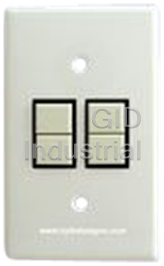
General Electric RP2-127 Switch Plate. 1-Gang for 2 Switches | White Color | Nylon Material
Part Number
RP2-127
Price
Request Quote
Manufacturer
GENERAL ELECTRIC
Lead Time
Request Quote
Category
Switch Plates
Datasheet

Extracted Text
GE Total Lighting Control Remote Control Low Voltage Switching Components and Applications Contents Lighting Automation Overview – Why Lighting Automation? 3 Remote Control Applications Overview – Low-Voltage Switching 4-5 Basic Components 6-15 Relays 6-7 12-, 24- and 48-Relay Capacity Relay Panels 8-9 Small Tubs and Frames 10-11 RS Series Momentary Switches 12-13 Switch Plates and Brackets 14-15 Adding Automation 16-21 Master Sequencers (Relay Group Control) 16-17 Smart Sweeper (Auto OFF with Blink Warning) 18-19 Outdoor Lighting Controller 20-21 Other Controls 22-27 Daylighting Controls 22-23 Occupancy Sensors 24-27 Additional Components 28-29 Low-Voltage Control Wire 28 Replacement Parts 29 Guideform Specification 30 Catalog Number Index 31 Lighting Automation Overview Why Lighting Automation? IGHTING IS THE SINGLE LARGEST USER The three basic system types include: of electricity in commercial and institutional J Remote Control Components (left above) L buildings. Automated controls can save up to The Remote Control solution provides a low-cost, 50% of this power by providing the right amount of modular component approach to lighting automa- light, where needed, when needed. These same controls tion. The system begins with a flexible, low-voltage can also help provide a safer, more productive work relay switching system. Automation devices are then environment while reducing building operation labor. layered on top of this switching platform. The basic relay switching platform and automation options Energy Codes — Setting The Baseline are summarized on the next two pages. Many lighting control best practices have also J Softwired Switching System (center above) become mandatory in many state energy codes. The Softwired Switching adds microprocessor intelligence new ASHRAE 90.1 Energy Standard*, the basis for many and dataline communications to simplify the design, state codes, includes mandatory lighting controls similar wiring and operation of the lighting automation to those specified in California’s Title 24, including: system, from standalone panels to small networks. J Automatic Shutoff Controls for Each Floor (Refer to GEA-TLCSWS for details.) These may be either occupancy sensing or time J Programmable Networked System (right above) based. If time based, the control device must also Programmable Networked Systems combine the incorporate an override switch which controls a power of the Personal Computer with distributed maximum of 5000 square feet and has an auto- intelligence in each relay panel to provide maximum matic time delay of not more than 2 hours. energy savings and occupant satisfaction. (Refer to J Manual Control of 50% of Lighting in Daylit Zones GEA-TLCGOLD). J Photocell or Astronomical Time Switch Control of Exterior Lighting Integration With Other Building Automation Systems GE Total Lighting Control Solutions GE is committed to developing and adapting GE offers a range of options to reflect the different controls to the specific needs of each building. control and operating requirements of different types Lighting controls must: of buildings (refer to publication GEA-TLCOVR8PG, J Respond to the needs of the occupants “Commercial and Industrial Lighting Automation J Provide value to the owner Options”, for a comparison). J Install readily J Operate flawlessly Our systems are designed to integrate seamlessly with other building automation systems. For design assistance call 1-877-584-2685 in the United States, or 1-877-584-2685 in Canada. *The revised version of ASHRAE 90.1 is now in the public review process. Adoption is expected in the 1999-2000 timeframe. 3 Remote Control Applications Overview Low-Voltage Switching Low-Voltage Switching Platform pages 6-15 LOW VOLTAGE WIRING The low-voltage switching platform consists of relay panels which are typically mounted in the electrical RELAYS closet. Each lighting load to be controlled is wired LOAD through a relay. The relays, in turn, are connected to LOW VOLTAGE WIRING LINE manual switches with low-voltage wires. The resulting LOCAL SWITCH switching platform has a number of benefits: J Any number of switches can control a single relay. This makes it possible to control the lighting from any number of locations, including a central switching console. J The status of each lighting load can be annunciated. This makes remote switching of lighting circuits code-compliant and practical. J Relays can be grouped for common control. This REMOTE PILOT LIGHT provides a low cost, reconfigurable, multi-pole SWITCH contactor function. J Low-voltage wiring reduces wiring cost by eliminat- ing the need for expensive conduit. This is especially important in long switch runs. Master Switch Control Of MASTER SWITCH GROUP CONTROL A Group Of Lighting Loads pages 16-17 MASTER SEQUENCER Simple automation can be added to the basic switching platform using a Master Sequencer. This basic controller mounts on an accessory plate in the relay panel, controlling a group of relays ON/OFF LOCAL while retaining separate control of each. When the SWITCH Master Switch is turned ON (OFF), the Sequencer pulses each of its ON (OFF) relay outputs sequentially. 12 A local switch can control an individual relay without affecting the others. A second input channel allows timeclocks, MASTER SWITCH MAINTAINED CONTACT DEVICES building automation systems or other maintained contact devices also to control the Sequencer. This meets the minimum requirements of the energy codes. However, it requires multiple OFF sweeps of the timeclock to ensure that individual overrides are caught after four hours. 4 Time Control Of Indoor Lighting pages 18-19 The Smart Sweeper provides a much more elegant solution for occupant-sensitive, indoor lighting automation. Like the Sequencer, it mounts on an accessory plate in the relay panel, with the timeclock or building automation system output wired to its input. When this contact is closed, the building is considered occupied; open, it’s unoccupied. This single contact can now initiate an intelligent operating scenario for all the connected lighting loads: TIME CONTROL OF INDOOR LIGHTING J Manual ON/Auto OFF SMART SWEEPER J Auto ON/Auto OFF 1 1 2 2 Contact Closed = Occupied Mode INDIVIDUAL 3 3 OCCUPANT The automation system closes the input contact SWITCH 4 4 before the earliest occupant arrives. In Auto ON 5 5 scenario, the Sweeper will turn on the lighting 6 6 7 7 when the contact closes. In Manual ON scenario, 8 8 occupants switch on the lighting for their areas as 9 9 they arrive. 10 10 Contact Open = Unoccupied Mode 11 11 12 12 Lights “blink” to warn occupants of an impending OFF sweep. Occupants can extend their stay, without having the lights go off, simply by pressing their switch. Areas not overridden go off in 5 minutes. At the end of the lighting override time (15 min. to 2 hr.) TIMECLOCK OR BUILDING AUTOMATION SYSTEM the Blink Warning process is repeated. (Note: the Blink Warning, Time Delay and Auto ON vs. Manual ON are user selectable.) Photocell Control Of Outdoor Lighting PHOTOCELL CONTROL OF OUTDOOR LIGHTING pages 20-21 The Outdoor Lighting Controller provides a simple way to control the three kinds of outdoor lighting PHOTOCELL “OCCUPIED” normally encountered in a commercial or institutional CONTACTS building: Security, Parking and Signage. The controller SECURITY itself is mounted in the relay panel; a single sensor is mounted outdoors. PARKING As with the Sweeper, the Outdoor Lighting Controller uses a contact closure from the BAS, time- SIGNAGE clock or security system to set the occupied/unoccupied status. Each type of lighting has its own output channel on the controller, with user-selectable trip levels: OUTDOOR PHOTOCELL CONTROLLER J Security. The Security output controls the con- nected relays (up to 3) ON at dusk, OFF at dawn. The trip point is adjustable from 2 to 20 fc. J Parking. Parking lot lights are turned on at dusk if the building is occupied. The lighting goes off when the building becomes unoccupied or the outdoor light level rises above the 2 to 20 fc threshold setting. A separate egress delay, adjust- able from 15 to 120 min, allows a grace period for people to exit the building grounds. J Signage. Signage is normally turned on at higher light levels: 20 to 200 fc. Signage is ON whenever the outside light levels are below this threshold and the building is occupied. 5 Basic Components Relays E RR SERIES RELAYS HAVE SERVED as the heart of low voltage lighting controls G for over 40 years. The basic power switching device, the relay serves as the foundation of a building’s lighting control solution. GE’s Remote Control panels and frames are con- figured for either RR7P or RR9P relays with a five-pin female connector. The user can simply remove a knockout in the low voltage barrier, snap the relay into place, and plug it onto the interconnect board. RR7P Operation Each relay employs a split low-voltage (24V) coil to move the line voltage contact armature to the ON(OFF) latched position. As illustrated on the RR7P Relay RR9P Relay opposite page for the RR7P, the ON coil moves the armature to the left when a 24 volt control signal is impressed across its leads. The armature latches in the ON position and will remain there until the OFF coil is energized. This operation provides several key control features: J Positive action. The relay always goes to the state commanded. For example, multiple OFF com- mands will keep the contacts in the OFF position. J Stable operation. Since the relay latches in the ON or OFF position, power outages do not result in a change of state. J Minimal power consumption. Control power is only required when the relay changes state. J Ability to support multiple input devices. After the relay responds to a momentary pulse, it is then “free” to accept another pulse from any other control devices wired to it. The relay position is always controlled by the last signal. Catalog # Description RR7P Standard 3-wire relay with 5-pin connector RR9P Operation RR9P Isolated pilot contact 5-wire relay with 5-pin connector The RR9P includes an auxiliary contact on the low- The RR7P and RR9P relays are designed for simple connection to TLC voltage side of the armature to provide status indication panels. Other relay wire terminations are available, including: for pilot light switches or indicator lights for remote RR7 Standard 3-wire relay with stripped leads annunciation of lighting status. It is also used to RR8 Pilot contact 4-wire relay with stripped leads provide status information to more highly automated RR9 Isolated pilot contact 5-wire relay with stripped leads GE TLC systems (refer to page 3 for overviews of RR7EZ Standard 3-wire relay with spade terminals other systems). RR8EZ Pilot contact 4-wire relay with spade terminals RR9EZ Isolated pilot contact 5-wire relay with spade terminals 6 relays Specifications RR7P RELAY OPERATION UL Listed, CSA Certified 1 Mounts in standard ⁄2” KO, .865”-.875” diameter, 14 or 16 gauge material Operates in any position Rated Capacity ARMATURE Lamp Load – 20 A Tungsten filament 125 VAC LOAD 20 A Ballast 277 VAC, 347 VAC Canadian ON (RED) Resistive Load – 20 A 277 VAC, 347 VAC Canadian 24 VAC (RECT) 1 Motor Load – ⁄2Hp @ 110-125 VAC 1 OFF (BLACK) 1 ⁄2Hp @ 220 - 277 VAC LINE Operating Environment ON COIL Temperature – 0 to 60°C (32 to 140°F) Relative Humidity – 10 to 95% RH, non-condensing OFF COIL Atmosphere – Non-explosive, non-corrosive 20 AMP/277 VAC Vibration – Stationary applications NEMA Level A (LINE CONTACTS) Endurance 50,000 cycles, full load 100,000 cycles, no load Line-Voltage Characteristics Contacts – SPST maintained (mechanical latching) Terminals – 2 Terminals TYPICAL ELECTRONIC DRIVER CIRCUIT ULN-2003A 2 Back-wiring holes per terminal Feedthrough wiring TTL OR OFF/BLACK CMOS Screw actuated clamps for use with #14-10 INPUT 24 VOLTS AWG solid or stranded copper wire only. (PULSE ON/RED INPUT) Low-Voltage Characteristics ULN-2003A RELAY DRIVERS 1 1 Split Coil – ⁄2 for “ON”, ⁄2 for “OFF” Compatible with standard interface/drivers, ULN-2003A Darlington transistor arrays Operating Voltage – Nominal 24-29 VAC (±10%) Rectified (Minimum at relay = 21 VAC rectified) 30-38 VDC (±10%) Filtered Note: Do not use DC with pilot or locator switches Duty Rating – Momentary 24 VOLTS Minimum Activating Pulse Time – 50 Milliseconds Coil Impedance – 75-85 Ohms at 60 Hz Unrectified NOTE RECTIFIER POLARITY 55-60 Ohms DC Resistance CLASS 2 TRANSFORMER Pilot Contact – 1 A 24-29 VAC Resistive Important Considerations and Restrictions RELAY DIMENSIONS Relays connected in parallel – Two or more relays connected in parallel, by grouping red leads and black leads, will operate together. The maximum number of relays connected in parallel is determined by 1.61 .91 1.72 (41) (23) (44) the capacity of the power supply and the switch lead lengths. (See the table on page 13). Pilot contacts connected in parallel – If the yellow switch connections for a group of RR9P relays are paralleled, any relay ON in the group will turn the pilot lighted switch ON. 1.41 1.53 (36) (39) Caution: 1 Do NOT use these relays to switch DC loads. This will damage the 5-PIN PLUG-IN CONNECTOR power contacts. RR7P RR9P LINE TERMINALS PIN 1 — YELLOW 2 For proper pilot light operation, use only half-wave rectified AC .67 PIN 2 — YELLOW (17) voltage for relay control. PIN 3 BLACK BLACK PIN 4 RED RED inches (millimeters) PIN 5 BLUE BLUE 7 Basic Components 12-, 24- and 48-Relay Capacity Panels COMPLETE RELAY PANEL consists of a tub, interior Tub… Interior… Power Supply… Cover… A with relays, power supply For Easy Installation and cover. The tub is normally mounted in the electrical closet adjacent to the lighting panel. Remote Control panel interiors provide isolation between line- and low-voltage sections of the panel, as well as the mounting frame for the relays, power supply and control devices. Interiors simply slide into the correspond- ing tub and bolt in place. Connec- tions for plug-in relays and 1. Mount tub 2. Pull wires hardwired switches, as well as the rectifier, are included on the interior’s motherboard. Power supplies combine two separate 40 VA transformers in one assembly. They connect to the motherboard via a simple 5-pin connector. Power supplies available are: RPWR115 (115 VAC, UL/CSA), RPWR277 (277 VAC, UL/CSA) and RPWR347 (347 VAC, CSA, available in Canada only). 3. Connect power supply to interior 4. Insert interior into tub Standard covers are available as Surface Lockable (SL suffix) or Flush Lockable (FL suffix). RPWRXXX DIMENSIONS 7.88 (200) 5. Remove knockout plugs from panel. 6. Snap in relays. Wire circuits. 3.25 2.13 (83) (54) Maximum Panel Capacities 4.06 2.63 (103) (67) Panel Size 12 24 48 inches (millimeters) RR7P/RR9P Relays 12 24 48 12-RELAY LIGHTING RMS8/16 2 4 4 AUTOMATION 24-RELAY LIGHTING PANEL RMS32 1 2 2 AUTOMATION PANEL RSP12/RCS12* 1 2 2 48-RELAY LIGHTING RPCON/RPCON3-OUT 2 4 4 AUTOMATION PANEL * See Installation Table on page 19. 8 relay panels Important Considerations And Restrictions When more than one transformer is used in accordance with US National Electric Code Section 725-32 and table 725-31(a) and control devices are operated by a common switch, connect the White low voltage secondary commons of both transformers by a common wire. Transformer primaries must be wired identically (correct polarity) to the same phase. Such installations are not permitted in Canada by Canadian Electric Code C22.1 subrule S 16-200 (4). 13 (330) DIMENSIONS 11.63 LOW VOLTAGE (295) AREA 16 (406) LINE VOLTAGE AREA 11.25 (286) 16 (406) inches (millimeters) 4.5 (114) RTUB12 RINTER0012RC RTUB12 RPWRxxx RINTER0012RC RCOV12SL 16 (406) LOW VOLTAGE AREA 22.5 22.30 (572) (566) LINE VOLTAGE AREAS 24 (610) 14 (356) 4.5 inches (millimeters) (114) RTUB24 RINTER0024RC 16 (406) RTUB24 RPWRxxx RINTER0024RC RCOV24SL LOW VOLTAGE AREA 36 35.76 (914) (908) LINE VOLTAGE AREAS 24 (610) 14 (356) 4.5 inches (millimeters) (114) RTUB48 RINTER0048RC RTUB48 RPWRxxx RINTER0048RC RCOV48SL 9 Basic Components Small Tubs and Frames RBS2 Small Tub The RBS2 small tub with surface-mount cover provides both a small relay panel and accessory enclosure. (Note: With screw cover only.) Frames Two frames are available. The RFTxxxEZN frames combine a single transformer power supply and spaces for three plug-in relays; the RRF78EZN provides spaces for up to six relays. RFTxxxEZN RRF78EZN J-Box Mount The RSENPWR-xxx J-Box cover mount provides a convenient method for installing remote relays or for providing a power pack for ceiling-mounted occu- pancy sensors. It mounts to a standard 4" x 4" or 11 11 4 ⁄16" x 4 ⁄16" electrical box. RSENPWR-xxx 10 tubs and frames DIMENSIONS 11.81 11.81 12 (300) (300) (305) 3.25 4.1 3.25 11.94 (303) (87) (104) (87) 2 (51) inches (millimeters) inches (millimeters) 3.42 (87) RFTxxxEZN RRF78EZN inches (millimeters) 4.81 (122) RBS2 4.81 2.75 (122) (70) 3.375 2.13 (86) (54) RSENPWR-xxx 4.25 (108) .94 (24) inches (millimeters) Catalog # Description Capacities RBS2 Tub with surface-mount, 2 frames… or shoebox cover 1 frame and 2 RMS8/16, 2 RPCON, 2 RPCON3-OUT, 1 RMS32, 1 RCS12 or 1 RSP12… or No frame and 4 RMS8/16, 4 RPCON, 4 RPCON3-OUT, 2 RMS32, 2 RCS12 or 2 RSP12 RRF78EZN 6-relay frame Up to 6 plug-in relays UL, CSA Listed Power tap for connecting to external power supply RFT178EZN 3-relay frame with 115 VAC, Up to 3 plug-in relays 50-60 Hz transformer and rectifier Power tap for connecting to RRF78EZN UL, CSA Listed Up to 8 sensors RFT278EZN Same as above with 277 VAC UL, CSA Listed RFT347EZN Same as above with 347 VAC Available in Canada only CSA Listed RSENPWR-115 J-Box frame with 115 VAC, 50-60 Hz 1 RR7P relay and up to 4 occupancy sensors transformer and single RR7P relay UL, CSA Listed RSENPWR-277 Same as above with 277 VAC UL, CSA Listed RSENPWR-347 Same as above with 347 VAC Available in Canada only CSA Listed 11 Basic Components RS Series Momentary Switches ANUAL OVERRIDE SWITCHES are momentary, single-pole, double-throw Mdevices wired to the relay using standard Class 2 control wiring. The RS2 series switches are designed for installation in mounting straps as shown or snap-in mounting in control panels (.76" x 1.28" rectangular hole required). They are available in three configurations: 1. Unlighted, 2-button 2. Locator lighted 2-button (0.03 amp, 28 VAC lamp)* 3. Pilot lighted 2-button, red dot “ON” (0.04 amp, 28 VAC lamp)* For fast, trouble-free wiring, each switch is supplied with five 0.187" quick disconnect terminals. Matching blank fillers and pilot lighted blanks are also available. Shown left to right: RS2-37, two RS2-37P, RS2-37K, RS2-37PK, RK0, RS2-37RL and RA2-37. Catalog # Catalog # Description Button/Face Color † Standard Key-operated (all have black collar) RS2 SERIES SWITCH TYPICAL DIMENSIONS RS2-32 RS2-32K Unlighted Ivory .89 .87 (23) (22) RS2-37 RS2-37K Unlighted White RS2-39 RS2-39K Unlighted Gray RS2-32L RS2-32LK Locator Light Ivory 1.38 1.16 RS2-37L RS2-37LK Locator Light White (35) (29) RS2-39L RS2-39LK Locator Light Gray RS2-32P RS2-32PK Pilot Light Ivory/Red Dot .188 (5) .76 X 1.28 RS2-37P RS2-37PK Pilot Light White/Red Dot QUICK DISCONNECT (19 X 33) TERMINALS RECTANGULAR RS2-38P Pilot Light Red/Black Dot MOUNTING HOLE RS2-38PA Pilot Light Clear Red inches (millimeters) RS2-39P RS2-39PK Pilot Light Gray/Red Dot .74 RS2-32RL RS2-32RLK Raise/Lower Ivory/Red Arrows (19) RS2-37RL RS2-37RLK Raise/Lower White/Red Arrows RS2-39RL RS2-39RLK Raise/Lower Gray/Red Arrows RK0 Replacement Key for K-suffix switches RA2-32 Blank Filler Ivory Face RA2-37 Blank Filler White Face SWITCH WIRING (BACK VIEWS) RA2-39 Blank Filler Gray Face RA2-38P Pilot Light Blank Red Lens ON ON † Key operated switches are supplied with 2 RKO keys. COM COM LOCATOR OFF OFF UNLIGHTED SWITCH LOCATOR LIGHT SWITCH RS 2-32 RS 2-32L RS 2-37 RS 2-37L For heavy-duty conventional-style toggle switches, RS 2-39 RS 2-39L see page 15. ON COM PILOT COM PILOT OFF PILOT LIGHT SWITCH PILOT LIGHT RS 2-32P ACCESSORY RS 2-37P RA 2-38P RS 2-39P * NOTE: Lamps are rated at 50,000 hours when using half-wave rectified power supply. Lamps are NOT replaceable. 12 switches LOW VOLTAGE SWITCHES – TYPICAL WIRING STANDARD SWITCH #20/3 AWG RED BLACK YELLOW WHITE 1600 FEET MAXIMUM* 1 RSWIRE-3 (standard class) RSWIRE-3P (plenum applications) LOCATOR LIGHT SWITCH #20/4 AWG 24V RED BLACK YELLOW WHITE 1600 FEET MAXIMUM* RECT 1 BLUE ROSWIRE-4 (standard class) ROSWIRE-4P (plenum applications) PILOT LIGHT SWITCH #20/4 AWG RED BLACK YELLOW WHITE 1600 FEET MAXIMUM* 1 RSWIRE-4 (standard class) RSWIRE-4P (plenum applications) MULTIPLE SWITCH CONTROL OF A SINGLE RELAY #20/4 AWG 1600 FEET MAXIMUM* RED BLACK YELLOW WHITE 1 RSWIRE-4 (standard class) RSWIRE-4P (plenum applications) FOR MORE THAN TWO SWITCHES, SPLICE CONTROL LEADS. FOR MASTER PLATE RMP2-35 (page 15), USE RSWIRE-25(P) SINGLE (OR MULTIPLE) SWITCH CONTROL OF A GROUP OF RELAYS #20/4 AWG MAXIMUM DISTANCE* RED BLACK YELLOW WHITE RSWIRE-4 (standard class) 1 RSWIRE-4P (plenum applications) RED BLACK YELLOW WHITE 2 Number *Maximum Switch Leg Distance in Feet (Meters): of Relays RED BLACK YELLOW WHITE #20 AWG #18 AWG #16 AWG #14 AWG in Parallel 3 1 1600 (488) 2550 (777) 4000 (1219) 6500 (1981) 2 750 (229) 1200 (366) 1900 (579) 3000 (914) 3 450 (137) 750 (229) 1200 (366) 1900 (579) Note: Relays 1, 2 and 3 are now permanently 4 325 (99) 500 (152) 825 (251) 1300 (396) 5 240 (73) 375 (114) 600 (183) 950 (290) wired as a group. You can’t control them individually. 6 180 (55) 300 (91) 450 (137) 725 (221) If the pilot contacts are wired in parallel as shown, 7 140 (43) 225 (69) 350 (107) 650 (198) turning ON any relay in the group will cause the pilot to light.** 8 110 (34) 175 (53) 275 (84) 450 (137) For more than 6 relays in parallel, use a Master Sequencer (RMS8, RMS16 or RMS32). ** Consult TLC Applications at1-877-548-2685 for information on selective switching using blocking diodes. 13 Basic Components Switch Plates and Brackets TANDARD SWITCH PLATES Catalog # Description Color / Material are available in single-gang size for one or two RS2 Switch Plates series switches or RA2 series accessories, and 2-gang RP2-112 1-Gang for 1 Switch Ivory Nylon S size for three or four switches or accessories. They RP2-116 1-Gang for 1 Switch Stainless Steel come in ivory, white or gray nylon and 302 stainless RP2-117 1-Gang for 1 Switch White Nylon steel. Switches and accessories snap into a metal RP2-119 1-Gang for 1 Switch Gray Nylon bracket (included with each RP2 plate) which mounts to a standard single- or 2-gang wallbox. RP2-122 1-Gang for 2 Switches Ivory Nylon Single-gang plates are furnished with an RPB2-1 RP2-126 1-Gang for 2 Switches Stainless Steel bracket and 2-gang plates with an RPB2-2 bracket. RP2-127 1-Gang for 2 Switches White Nylon All necessary mounting screws are included. RP2-129 1-Gang for 2 Switches Gray Nylon RP2-232 2-Gang for 3 Switches Ivory Nylon RP2-236 2-Gang for 3 Switches Stainless Steel RP2-237 2-Gang for 3 Switches White Nylon RP2-239 2-Gang for 3 Switches Gray Nylon RP2-242 2-Gang for 4 Switches Ivory Nylon RP2-246 2-Gang for 4 Switches Stainless Steel RP2-247 2-Gang for 4 Switches White Nylon RP2-249 2-Gang for 4 Switches Gray Nylon Brackets RPB2-1 1-Gang for 1 or 2 Switches Steel RPB2-2 2-Gang for 3 or 4 Switches Steel RP2-242 RP2-112 2.26 4.04 .100 (3) (55) (101) 1.671 3.48 (42) (88) RP2 SERIES .906 1.81 (23) (46) SWITCH PLATE AND RPB2 SERIES 3.75 3.28 2.375 1.28 (95) (83) (60) (33) BRACKET DIMENSIONS 2.75 4.50 .188 (5) (70) (114) .756 .906 1.812 (19) (23) (46) 2.375 (60) 4.50 1.187 (114) (30) 1 GANG 1 GANG 2 GANG 2 GANG FOR 1 SWITCH FOR 2 SWITCHES FOR 3 SWITCHES FOR 4 SWITCHES ALL DIMENSIONS ARE TYPICAL inches (millimeters) 14 switch plates Master Plate The RMP2-35 Master Plate conveniently mounts eight RS2 series switches and/or RA2 series accessories. The satin-finish, anodized aluminum frame mounts on a zinc die-cast base. A key-operated lockout switch is located in the unit to allow the switches to be deactivated. One RK1 key is included with the plate. For typical lockout circuit wiring diagrams, phone 1-877-584-2685 in the (USA) and (CANADA). The 11 11 Master Plate mounts directly on a 4 ⁄16" x 4 ⁄16" square box using the “S” bracket packed with the unit. (It may NOT be mounted on a 4" square box). Catalog # Description Color RMP2-35 8-Switch Master Plate Aluminum with Black Trim RK1 Replacement Key (1 furnished with unit) Heavy-Duty Toggle Switches RMP2-35 MASTER PLATE DIMENSIONS The GE 5935 series single-pole, double-throw, 4.88 .73 (19) (124) center OFF, momentary switches allow the designer 4.05 SPACING ADJACENT ELECTRICAL BOXES (103) FOR GANGED MOUNTING to match the appearance of conventional switches. 3.42 (87) 4.88 (124) The devices are rated at 15 Amp, 277 VAC and require a standard switch plate, which is not included. FRONT VIEW UP UP UP WITHOUT COVER PLATE LOCKOUT 4.88 3.48 Catalog # Description / Toggle Color (124) (88) SWITCH 4.88 (124) 1.28 (33) GE 5935-1G Brown TYP. GE 5935-2G Ivory UP UP GE 5935-7G White 2.75 (70) inches (millimeters) GE 5935-9G Gray GE 5935-0LG Locking Switch with 2 Keys UP MOUNTING HOLES GE 5099-0 Replacement Key for GE 5935-0LG FOR BOX MOUNTING WITH “S” BRACKET UP The GE 5935 Series does not offer pilot light or locator light versions. MOUNTING HOLES 11 FOR WALL MOUNTING STANDARD 4 ⁄16" (119mm) SQUARE ELECTRICAL BOX 15 Adding Automation Master Sequencers Relay Group Control HE RMS MASTER SEQUENCER provides a master ON/OFF function for a group T of relays while retaining individual relay control. This is a basic building block for automation. A group of lighting circuits, such as all general office lighting, may be turned OFF at the end of the day while allowing an individual to override a particular area back ON with a local switch. The Master Sequencer is an electronic switch with two independent inputs. It is available in three sizes allowing independent ON/OFF control of 8, 16 or 32 relays. In addition to master group control, it also allows switchleg extension and the conversion of maintained input signals to momentary. Master Group Control The RMS turns each associated relay ON or OFF, one at a time, when it detects a change of state of a switch input. When the ON side of a master switch is actuated, the RMS detects this action and provides a pulse to each of its ON output terminals in rapid RMS32 RMS16 succession (1-4 seconds). Since each relay output is pulsed individually, a large number of relays can be controlled as part of each master group. Master Switchleg Extension When relays are paralleled to create a group (see bottom diagram on page 13), the switchleg length must be restricted because of voltage drop. This restriction does not apply to the RMS. A master switch may be up to 1000 feet from the RMS, regardless of the number of relays controlled by the unit. Maintained-To-Momentary Input Conversion Each input channel on the RMS will accept any number of 3-wire momentary switches, one 3-wire maintained switch or one 2-wire SPST switch. This allows the RMS to interface directly with typical control devices, such as timeclocks, while still providing local master switch control. the OFF (black) leads connect to the “B” output ON/OFF Operation bank (right side) and to the black relay terminals A mode jumper allows the RMS to be used as an (see photos and Typical Wiring diagram opposite). ON/OFF master controller or as an ON or OFF device similar to the old GE Motor Master (RMS5BL ON Or OFF Only or RMS5RL). In the ON/OFF mode, either master In the ON or OFF Only mode, actuating either switch controls the relays both ON and OFF. The ON master switch pulses both the A and B output banks. (red) leads connect to the “A” output bank (left side) For Master OFF Only control, the black relay leads and to the red terminals of the relays to be controlled; connect to both A and B outputs, doubling the capacity of the unit. 16 sequencer “B” OUTPUTS (OFF) RMS DIMENSIONS 1.72 4.50 (44) (114) 1.81 (46) 4.50 3.28 RMS8/16 (114) (83) Catalog # Description Specifications RMS8 Master Sequencer 24-29 VAC + 10%, 2 VA for Controlling up to ON/OFF Mode: 8 ON Outputs, 8 OFF Outputs 8 Relays ON/OFF OFF Only (ON Only) Mode: 16 Outputs Up to 3 Relays per Output 0 to 55°C (32 to 131°F) Indoor applications, <1 second cycle time RMS16 Master Sequencer 24-29 VAC + 10%, 2 VA for Controlling up to ON/OFF Mode: 16 ON Outputs, 16 OFF Outputs 16 Relays ON/OFF OFF Only (ON Only) Mode: 32 Outputs Up to 3 Relays per Output 0 to 55°C (32 to 131°F) Indoor applications, 1.7 second cycle time RMS32 Master Sequencer 24-29 VAC + 10%, 2 VA for Controlling up to ON/OFF Mode: 32 ON Outputs, 32 OFF Outputs 9.50 7.91 RMS32 (241) (201) 32 Relays ON/OFF OFF Only (ON Only) Mode: 64 Outputs Up to 3 Relays per Output 0 to 55°C (32 to 131°F) Indoor applications, 3.3 second cycle time RMS Installation The RMS mounts in standard panels and cabinets and does not require special inches (millimeters) orientation. RMS MASTER SEQUENCER TYPICAL WIRING (also see photos on opposite page) MODE JUMPER RMS #20/4 AWG 1600 FEET MAXIMUM RSWIRE-4 (standard class) RSWIRE-4P (plenum applications) TO OTHER RMS 24V must be on the RECT COM same phase BLUE WHITE TYPICAL LOCAL SWITCH MASTER ON/OFF SWITCH RED BLACK YELLOW WHITE 1 TIMECLOCK OR BAS RED BLACK YELLOW WHITE 2 RED BLACK YELLOW WHITE 3 17 “A” OUTPUTS (ON) Adding Automation Smart Sweeper Auto OFF with Blink Warning HE RSP12 REMOTE CONTROL SMART SWEEPER takes the concept of the Master Sequencer one step further. Like the RMS, the Sweeper allows T groups of lighting circuits to be turned ON or OFF automatically, allows switchleg extension, and converts maintained input signals to momentary. However, the Sweeper is designed with a higher level of intelligence, reducing hardwiring for specific functions and increasing flexibility. An “Occupied” contact simplifies scheduling and enables several powerful automation functions, including automatic ON, after-hours OFF sweeps based on a user-selectable time delay, and blink warning. The Sweeper, designed for applications like general lighting in a small office building, provides users with automatic functions for energy savings while allowing individual occupant control. Because it offers more functions, the Sweeper is configured differently than the RMS. The Sweeper provides one master input, and 12 individual switch inputs. Each input will accept any 2- or 3-wire switch, including a 2-wire maintained input (refer to Typical Switch Wiring diagram on opposite page). Inputs may also be wired together for control of small subgroups. Each of the 12 individual inputs corresponds to one of the 12 relay outputs, allowing direct occupant override for any relay. TYPICAL SWITCH WIRING #20/2 AWG 1000 FT. MAX. RED BLACK WHITE RED JUMP RED TO BLACK MAINTAINED BLACK RED BLACK YELLOW WHITE 1 WHITE ISOLATED RED CONTACT BLACK #20/2 AWG 1000 FT. MAX. WHITE ON TLC PANEL RED MOTHERBOARD BLACK #20/2 AWG WHITE JUMP BLACK TO WHITE RED RED TYPICAL BLACK 2-WIRE BLACK WHITE MOMENTARY BLUE RELAY RED PUSH BUTTON BLACK RSP12 #20/3 AWG 1000 FT. MAX. WIRING WHITE RSP12 RED BLACK WHITE RED Maintained-To-Momentary Interface STANDARD BLACK WHITE 3-WIRE The RCS12 Switch Interface is identical in form to RED MOMENTARY BLACK the RSP12. Without any advanced control functions, #20/3 AWG 1000 FT. MAX. WHITE however, the RCS12 simply converts any switch input RED BLACK to a momentary output. Relay outputs can drive up WHITE RED to three relays wired in parallel. STANDARD BLACK WHITE 3-WIRE RED MAINTAINED BLACK WHITE 18 sweeper Occupied Contact RSP12 A timeclock or BAS can easily interface to the WARN AUTO ON OCCUPIED 0 YES YES NO NO RED WHITE Sweeper using the Occupied contact. The contact is CLOSED to indicate normal working #20/2 AWG 1000 FEET MAXIMUM hours for the building, then OPEN after hours. Properly connecting and scheduling the Occupied MAINTAINED ISOLATED CONTACT contact determines when other functions will IN TIME CLOCK (3RD PARTY) be enabled. If an automated interface is not OCCUPIED CONTACT required, the Occupied contact may simply be RSP12 connected to a manual switch. WARN AUTO ON OCCUPIED 0 YES YES Time Delay NO RED WHITE NO RSP12 DIMENSIONS Many energy codes require automatic OFF of 0 0 = NO TIME DELAY 1.72 4.50 any lighting turned on after hours. The Sweeper 1 = 15-MINUTE DELAY (44) (114) 2 = 30-MINUTE DELAY provides a selectable delay in 15-minute 3 = 45-MINUTE DELAY 1.81 …ETC. TO… (46) 8 = 2-HOUR DELAY increments up to two hours. When the option 9 = 1-MINUTE TEST is selected, an occupant’s after-hours override TIME DELAY will be turned OFF automatically after the selected time. Each override carries its own RSP12 delay, so occupants in different areas of the WARN AUTO ON OCCUPIED 0 YES YES NO NO RED WHITE building aren’t affected by activity in other zones. WARN Blink Warning 1 O YES N When lighting is due to be turned OFF, either NO 10.50 7.91 at the end of normal working hours or at the (267) (201) end of a timed override, the Sweeper can warn the occupants by blinking the lights five minutes WARN SWITCH in advance, giving anyone still in the building RSP12 time to override the system for his area. WARN AUTO ON OCCUPIED 0 YES YES Auto ON NO NO RED WHITE Lighting can be turned ON automatically at AUTO ON 2 the start of normal working hours (when the YES Occupied contact closes) by setting the Auto NO inches (millimeters) ON switch to “Yes”. When Auto ON is set to “No”, arriving occupants must switch the AUTO ON SWITCH lights on manually. Catalog # Description Specifications RSP12 PANEL MOUNTING RSP12 Smart Sweeper 24-29 VAC + 10%, 1 VA for Automating up to 12 Relays 12 Switch Inputs plus 1 Master Input ON/OFF Switching plus 12 Relay Outputs (up to 3 relays per output) Advanced Control Functions 0 to 55°C (32 to 131°F) Indoor applications, 1.5 seconds cycle time RCS12 Remote Control Switch Converter 24-29 VAC + 10%, 1 VA for Converting Any Switch Input to 12 Switch Inputs plus 1 Master Input 12-RELAY Momentary Otnput 12 Relay Outputs (up to 3 relays per output) LIGHTING 0 to 55°C (32 to 131°F) AUTOMATION 24-RELAY LIGHTING PANEL Indoor applications, 1.5 seconds cycle time AUTOMATION PANEL Installation 48-RELAY LIGHTING AUTOMATION PANEL The RSP12 or RCS12 should be installed in a lighting automation panel or an accessory cabinet. While two units may be stacked on top of each other inside the lighting automation panel, wiring becomes complex. GE recommends typical installations as follows: 12 relays: 12-relay panel with one RSP12/RCS12 mounted in the panel 24 relays: 24-relay panel with one RSP12/RCS12 in the panel and one in accessory cabinet 48 relays: 48-relay panel with two RSP12/RCS12 in the panel and two more in accessory cabinet 19 Adding Automation Outdoor Lighting Controller OR A SMALL OFFICE OR RETAIL STORE, the most common outdoor lighting needs include F security lighting, parking lot and signage. All three types can be easily automated using a combination of a photosensor to detect outdoor light levels and the RPCON3-OUT Outdoor Lighting Controller. Like the Sweeper, the Outdoor Lighting Controller uses an “Occupied” contact to interface to a timeclock, BAS or simple switch. The controller combines daylight information gathered from the photosensor and occupancy information from the “Occupied” contact to turn exterior lighting ON or OFF at the appropriate times. For example, a retail store may need security lighting to turn on whenever it is sufficiently dark outside, whether or not the store is open. However, even after dark, signage should only turn on when the store is ready for business. The RPCON3-OUT is designed to simplify these decisions for the owner and installer, taking the complexity out of outdoor lighting control. Daylight Input Each output is dedicated to one type of outdoor The RPCON3-OUT controller must be used with lighting: Security, Parking and Signage. Each output the RPSEN3-OUT photosensor. For convenience, the has its own adjustable set point to indicate what level two products may be ordered as a package under the of daylight (or darkness) should trip the lighting ON. catalog number RPHOTO3-OUT. The photosensor The user may adjust settings simply by turning the head is mounted on the building roof facing the dial. An automatic “deadband” and a five-minute northern sky, and wired back to the controller to time delay help eliminate nuisance switching (time provide information on the level of daylight outside. delay can be bypassed for setup and testing). Intelligent Outputs Parking Lot Egress Delay The controller’s three independent outputs are If the owner chooses, the parking lot lighting will each capable of driving up to three relays wired in stay on for a set time after closing to allow customers parallel. They may also drive other smart inputs, and employees time to depart safely. The egress delay which include a master input on another controller for parking lot lighting can be set in 15-minute such as the RMS or Sweeper, or the channels of a GE increments up to 2 hours. Softwired Contactor panel. (Call 1-877-584-2685 for more details on using the Outdoor Lighting Control- Smart Scenarios ler with the Softwired Contactor). Smart scenarios built into the RPCON3-OUT control the three outputs as follows: J Security – ON at dusk, OFF at dawn. This output always follows the photosensor. J Parking – Follows the photosensor while “Occupied.” Going “Unoccupied” causes the unit to turn the lights OFF after the egress time delay has elapsed. J Signage – Also follows the photosensor while “Occupied.” Going “Unoccupied” immediately turns the lights OFF with no time delay. 20 outdoor Catalog # Description Specifications RPCON3-OUT DIMENSIONS RPCON3-OUT Outdoor Lighting Controller 24-29 VAC/VDC + 10%, 1 VA with Built-in Scenarios and Sensor Input: 3 #20 AWG Wires 1.72 4.50 Three Outputs for Security, 3 Intelligent Outputs (44) (114) Parking and Signage Lighting Up to 3 Relays or 1 Smart Input per Output 1.81 (46) 0 to 55°C (32 to 131°F) Controller mounts indoors Range (fc) – user selectable per output: 2-20 fc (Security and Parking) 20-200 fc (Signage) 5.00 3.28 Deadband: (127) (83) 6 fc (Security and Parking) 4 fc (Signage) RPSEN3-OUT Outdoor Photodiode Weatherproof, -30 to 50°C (-20 to 120°F) 1 Sensing Module ⁄2" MPT, facing north RPHOTO3-OUT Package – Outdoor Lighting inches (millimeters) Controller (RPCON3-OUT) with Photosensor (RPSEN3-OUT) RPCON3-OUT AND RPSEN3-OUT TYPICAL WIRING RPSEN3-OUT DIMENSIONS “OCCUPIED” CONTACTS 1.30 (33) RED BLACK YELLOW WHITE 1 RPSEN3-OUT 1.86 (47) OUTPUTS TO RELAYS inches (millimeters) AND/OR SMART INPUTS SUCH AS RPCON3-OUT CHANNEL TERMINALS ON SOFTWIRED CONTACTOR A 24 VAC 21 Other Controls Daylighting Controls LC DAYLIGHTING CONTROLS PROVIDE: Controller J A reliable switching system for each type of daylit The RPCON control unit is normally mounted in T space. the electrical closet with the relay panel to simplify J Easy calibration and stability over time. calibration. The installer selects the switching range J Simple integration with the lighting control panels and then enters the high and low setpoints of the and switches. deadband, which is needed to avoid an oscillating condition. Meters and calibration charts are not Sensors For A Variety Of Space Needs required. In normal operation, the controller has a TLC uses four different photosensors to meet the 3-minute time delay to eliminate nuisance switching. needs of the space and provide a very stable signal: Time delay can be bypassed for setup and testing. J Interior Space with Daylighting – RPSEN-IN Interior spaces with windows providing abundant Integration And Occupant Overrides daylight require a sensor capable of tracking the The photocell controller provides three indepen- lighting falling onto the workspace. Direct lighting dent outputs which may be connected directly to from the window must be excluded. Switching relays or to another controller such as the Master ranges must correspond to typical office lighting Sequencer or Sweeper. Individual override switches levels of 30 to 70 fc. The sensor sheds lamps based may be connected to each relay, or a master switch on adequate daylighting, reducing lighting levels may be added to provide manual override of all three until the sensor activates the lamps ON again. outputs. A separate Photocell Enable/Disable input J Atrium Spaces – RPSEN-ATR allows the daylighting function to be disallowed Atriums, areas with multi-story glass expanses, during unoccupied periods. provide higher daylighting levels than in a typical perimeter office space. To control lighting effectively within atrium spaces, the sensor must average the brightness of the ceiling without being exposed to direct daylight. On dark or rainy days the lighting should be left ON. This requires a switching range of 100 to 1,000 fc. J Interior Spaces with Skylights – RPSEN-SKY While similar to atriums, the physical layout requires sensors in these spaces to be mounted in the skylight, facing upward. Exposing the sensor to direct daylighting requires switching levels of 1,000 to 10,000 fc. J Exterior Lighting – RPSEN-OUT The RPSEN-OUT is designed for exterior mounting facing north to provide a signal for switching exterior lighting. It should not be confused with the RPCON shown with RPSEN-ATR RPSEN3-OUT photosensor, as described on page 20, which is is used ONLY with the RPCON3-OUT controller. RPSEN- SKY RPSEN-OUT RPSEN-IN 22 photocell OFF ON DELAY ENABLE RANGE SELECTOR RPCON TYPICAL WIRING 24 VAC 24VAC COM RELAY OUTPUTS (3 MAXIMUM) RED BLACK RED BLACK RED BLACK YELLOW WHITE RED RPCON 1 BLACK 5 6 7 4 3 8 2 9 1 10 HIGH MASTER MASTER SWITCH SWITCH 5 6 4 7 3 8 ON-RED ON-RED 2 9 1 10 LOW OFF-BLK OFF-BLK COMMON COMMON PHOTO- SENSOR CELL BLACK WHITE RED BLUE DRAIN ENABLE ON COM TO PHOTODIODE SENSOR DIMENSIONS SPST MAINTAINED SPDT 1.72 4.50 MASTER MOMENTARY (44) (114) PHOTOCELL SWITCH MASTER ENABLE/DISABLE 1.81 SWITCH (46) 4.50 3.28 Catalog # Description Specifications (114) (83) RPCON Photocell Controller 24-29 VAC + 10%, 2 VA for use with Sensor Input: 4 #20 AWG Wires Photosensors (plus shield for noisy environments) below Control Inputs: Maintained Photocell Enable and RPCON Maintained or Momentary Master Override Input Delay: 3 Minutes (with override for testing) Pulse Outputs: 3 Isolated Dry Contacts Range Selector (fc): 1-10, 10-100, 100-1,000, 1,000-10,000 Adjustments: Low and High Setpoints 1.15 (29) on Deadband with LED Indication 2.00 RPSEN-IN The RPSEN Series Photosensors below are used with the RPCON Controller, (51) and are wired using 4 #20 AWG wires (Red/Black/White/Blue) 1.28 RPSEN-IN Interior Typical application: 30-70 fc for perimeter offices (33) Photosensor Indoor use only, 0 to 50°C (32 to 120°F) RPSEN-ATR Atrium Typical application: 100-200 fc for atriums Photosensor Indoor use only, 0 to 50°C (32 to 120°F) 2.25 (57) RPSEN-ATR RPSEN-SKY Skylight Typical application: 1,000-2,000 fc for skylights RPSEN-SKY Photosensor Indoor use only, 0 to 50°C (32 to 120°F) RPSEN-OUT Outdoor Typical applications: Photosensor 2-5 fc for parking lots 10-20 fc for canopies 30-50 fc for signage 300-500 fc for security lights Weatherproof, -30 to 50°C (-20 to 120°F) 1.35 (34) RPSEN-OUT 1.48 (38) inches (millimeters) 23 Other Controls Occupancy Sensors CCUPANCY SENSORS ARE SIMPLY another type of switch — an automatic switch. O For maximum flexibility, GE offers several types of occupancy sensors. Four low-voltage units (three ceiling-mount and one wall-mount switch) are designed to be compatible with GE TLC relay panels, and are described on the next three pages. There are three low-voltage “stand-alone” ceiling-mount sensors which operate with their own power/relay switchpack, and a line-voltage wall-mount switch which replaces a standard wall switch (See page 27). Each ultrasonic sensor produces a low intensity, inaudible sound. The units detect changes in the sound waves caused by motion in the room, but do not respond to audible noises. Low-Voltage TLC Ceiling-Mount Sensors RSENSOR-X DIMENSIONS Low-voltage TLC-compatible ceiling-mount occupancy sensors draw power directly from the relay panel. They can simplify wiring and give the designer extra flexibility. This includes using a low-voltage switch to override the sensor, using one sensor to control a group of relays, and extending coverage 1.62 (41) through a master/slave configuration (see diagrams on opposite page). 6.25 2.32 Tying occupancy sensors together in a master/slave (159) (59) configuration allows any sensor in the group to turn inches (millimeters) ON a single circuit. As one example, this could be very useful in a long hallway where lighting is unscheduled, particularly if the hallway is not straight. Motion from an occupant entering any section of the corridor would be detected by the RSENSOR-X nearest sensor, immediately lighting up the entire RANGE MINUTES ADJUSTMENT hall. Separate circuits for each sensor are not CONTROLS necessary. 12 When the sensor detects motion, it pulses the relay ON Minutes Minimum Maximum 30 by momentarily connecting red (ON) to white (COM). Sensitivity Sensitivity Seconds If no further motion is detected during the user-selected time delay, the sensor “times out” and pulses the relay OFF by connecting black (OFF) to white. The LED comes on each time the unit senses Catalog # Description Specifications motion, indicating the time delay has reset. However, RSENSOR-1 One-Way 29 VAC± 10%, 3 VA, Fused Room Sensor Four Teflon Pigtails it doesn’t pulse the relay ON every time; only if the Time Delay: 30 seconds to 12 minutes relay was previously pulsed OFF. Motion sensitivity Indoor use only and time delay are both adjustable. RSENSOR-2 Two-Way Same as above with 3 Each sensor mounts through a single ⁄4" hole in Room Sensor Five Teflon Pigtails the ceiling tile. It should be positioned to have an RSENSOR-H Hallway Same as above with Sensor Five Teflon Pigtails unobstructed “view” of the space, but not face the 24 occupancy doorway where it may pick up outside motion. The line of sight must be through air. The sensor will not RSENSOR-X TYPICAL WIRING “see” through glass partitions or curtains. A mounting ON/OFF SENSOR CONTROL height of 10 feet or less is desirable. Do not mount WITH DIRECT SWITCH OVERRIDE OPTION where forced air will blow directly at the unit. #20/4 AWG Three different ceiling-mount sensors cover the 1000 FEET MAXIMUM RSWIRE-4 (standard class) range of applications normally encountered in RSWIRE-4P (plenumapplications) commercial spaces: one-way, for small rooms; two-way, #20/3 AWG 1000 FEET MAXIMUM for larger rooms; and hallway, for corridors and 24V RSWIRE-3 (standard class) RED BLACK YELLOW WHITE RECT 1 RSWIRE-3P (plenumapplications) BLUE warehouse applications. J One-Way Room Sensor MANUAL OVERRIDE SWITCH The RSENSOR-1 one-way room sensor provides coverage of a typical enclosed office, conference SENSOR CONTROL OF A GROUP OF RELAYS room or small classroom up to 900 square feet. J Two-Way Room Sensor RED BLACK YELLOW WHITE 24V RECT 1 The RSENSOR-2 two-way room sensor is designed BLUE RED BLACK YELLOW WHITE 2 to control larger rooms up to 2100 square feet. #20/4 AWG RED BLACK YELLOW WHITE 500 FEET MAXIMUM Multiple sensors may be wired in a master/slave 3 RSWIRE-4 (standard class) RSWIRE-4P (plenum applications) configuration to provide coverage of even larger areas. Note: Relays 1, 2 and 3 are now permanently Large open spaces can be divided into individually wired as a group. You can’t control them individually. Maximum of 3 relays in parallel. controlled spaces by alternating frequencies on adjacent sensors. However, GE TLC recommends MASTER/SLAVE CONFIGURATION FOR EXTENDED COVERAGE you consider alternative approaches to controlling TO OTHER large open spaces. Call 1-877-584-2685 for applica- SLAVE SENSORS tion assistance. SLAVE (AUXILIARY) MASTER SENSOR RSENSOR-X COVERAGES SET TIME DELAY TO MINIMUM CONTROLS TIME DELAY AND ACTIVATES RELAY RSENSOR-1 CORRIDOR WAREHOUSE MOUNTING HEIGHT OF MOUNTING HEIGHT OF 10 FEET 21 FEET 28 30 (8.6) (9.2) J Hallway Sensor The RSENSOR-H hallway sensor is designed 24 (7.4) specifically for use in corridors and warehouses 30 (9.2) feet (meters) where walking is the predominant motion to be MOTION-AT-DESK COVERAGE 1 ⁄2 STEP WALK COVERAGE detected. RSENSOR-H should not be used in RSENSOR-H RSENSOR-H 100 60 100 (30.7) (18.5) (30.7) classrooms or offices. Mounted in a corridor at 10 feet from the floor, a single sensor provides coverage of 14 x 100 feet. RSENSOR-2 Mounted in a warehouse at 21 feet, the coverage is 56 60 (17.3) (18.5) reduced to 10 x 60 feet. Additional coverage may be obtained by wiring multiple sensors in a master/slave configuration as shown above. 10 14 (4.3) (3) feet (meters) 24 (7.4) 36 (11) WALKING MOTION COVERAGE FORKLIFT MOTION COVERAGE feet (meters) MOTION-AT-DESK COVERAGE 1⁄2 STEP WALK COVERAGE 25 Other Controls Occupancy Sensors continued Low-Voltage TLC Wall-Mount Sensor While the ceiling is the ideal place for mounting RSEN-WLV COVERAGE an occupancy sensor, some applications may require SENSOR a wall-mount sensor. The RSEN-WLV wall-mount occupancy sensor is a 20 24 (6.1) (7.3) low-voltage TLC-compatible ultrasonic motion sensor which replaces conventional wall switches in rooms up to 400 square feet. This white sensor/switch fits into a designer-style wallplate (not included). 25 (7.6) 30 (9.1) The sensor offers both Manual ON and Automatic ON modes, selectable by the user. In Manual ON feet (meters) mode, the occupant turns on lights when entering MOTION-AT-DESK COVERAGE the room by pressing the switch. In Automatic ON 1 ⁄2 STEP WALK COVERAGE mode, lights turn ON automatically when a person enters the room. In either mode, lights will remain Wallplate not included ON as long as the room is occupied. After the room is vacated, lights turn OFF automatically after a user- selectable time delay. Lights may also be turned OFF by pressing the switch; even if the room is still RSEN-WLV TYPICAL WIRING occupied, lights will stay off. ON/OFF SENSOR CONTROL Both time delay and motion sensitivity are user adjustable. The time delay may be adjusted from 15 seconds for testing to 15 minutes for operation. #20/3 AWG 1000 FEET MAXIMUM Normal time delay setting is 6 to 8 minutes. An RSWIRE-3 (standard class) RED BLACK YELLOW WHITE 24V RECT RSWIRE-3P (plenum applications) 1 adjustable entry sensitivity control avoids false BLUE activation from the corridor. If the lights go OFF for lack of motion during the SENSOR CONTROL OF A GROUP OF RELAYS selected time delay period, a 10-second “grace” period begins which allows the lights to be turned #20/3 AWG ON again with motion, even in the Manual ON 1000 FEET MAXIMUM 24V RED BLACK YELLOW WHITE RECT RSWIRE-3 (standard class) 1 mode. After this 10-second period, the lights can be BLUE RSWIRE-3P (plenum applications) RED BLACK YELLOW WHITE turned ON again by pressing the button. 2 RED BLACK YELLOW WHITE 3 RSEN-WLV CONTROLS RED BLACK YELLOW WHITE 4 Switch to M for Manual On Switch to A for Auto On Note: Relays 1, 2, 3 and 4 are now permanently RSEN-WLV DIMENSIONS wired as a group. You can’t control them individually. Maximum of 3 relays in parallel. 1.5 1.938 Sensitivity Time Delay (38) (49) Adjustments, Adjustment, clockwise clockwise M A 1.188 1.313 minimum 15 seconds Range Time (30) (33) Area Entry Delay to to maximum 15 minutes 1/4 15 4.125 3.813 3.25 2.625 (105) (97) (83) (67) Catalog # Description Specifications RSEN-WLV 24 VAC, 24-29 VAC± 10% ON/OFF Ultrasonic 1VA Max. for each sensor, 7VA Max. for each GE relay Wall Switch Sensor Time Delay: 15 seconds to 15 minutes inches (millimeters) Single-Gang Flush Mount UL Listed 26 Stand-Alone Ceiling-Mount Sensors For some applications, such as individual offices RSEN-XX TYPICAL WIRING TO ADDITIONAL SWITCHPACKS (max. of 10) and conference rooms, occupancy sensors do not AND SENSORS (max. of 5 per switchpack) need to connect to the relay panel. Ceiling-mount RTPACK-12 sensors, with their own transformer-powered relay LOAD switchpacks, simply replace line-voltage switches to USE BLACK LEAD FOR 120 VAC control individual spaces. USE ORANGE LEAD FOR 277 VAC CAP UNUSED LEAD. The low-voltage RSEN-xx series ceiling-mount #20/3 AWG OPTIONAL RSWIRE-3 (standard class) MANUAL OFF sensors are identical in size and appearance to the RSWIRE-3P (plenum applications) LINE-VOLTAGE SWITCH TLC-compatible RSENSOR-x models. However, a (USE ONLY ONE) switchpack containing a Class 2 transformer and a relay is required for sensor power and to switch the lighting circuit. Each switchpack can power up to five sensors. Four RSEN-xx sensors are available to provide the LINE coverage for a broad range of applications: J Small Room Sensors The small area RSEN-SM sensor provides coverage for a small office, classroom or other small space Catalog # Description Specifications up to 500 square feet. RSEN-SM One-Way Room Sensor 15 VDC from RTPACK-xx only* for Small Areas Time Delay: 15 seconds to 30 minutes J Medium Room Sensor Indoor Use Only The medium room RSEN-MD sensor provides RSEN-MD One-Way Room Sensor Same as above coverage up to 900 square feet. (See RSENSOR-1 for Medium Areas coverage diagram on page 25.) RSEN-LG Two-Way Room Sensor Same as above J Large Room Sensor for Large Areas The large area RSEN-LG sensor, designed for large RSEN-2H Two-Way Hallway Sensor Same as above offices and classrooms, can cover up to 2100 RTPACK 120/277 VAC Switchpack Input: 120 or 277 VAC ±10% 60 Hz Output: 15 VDC 200 mA to operate up to 5 sensors square feet. (See RSENSOR-2 coverage diagram on UL Listed, CSA Certified page 25.) RTPACK-347 347 VAC Switchpack Input: 347 VAC ±10% 60 Hz J Hallway Sensor Output: 15 VDC 200 mA to operate up to 5 sensors The RSEN-2H sensor provides coverage in hallways CSA Certified Available in Canada only and warehouses similar to the RSENSOR-H. (See coverage diagram and descriptions on page 25.) * Sensors and Switchpacks are interconnected using #18 AWG Class 2 wiring per NEC 725. Line-Voltage Wall-Mount Sensors Catalog # Description Specifications The RSEN-WX series line-voltage wall-mount RSEN-W12 120/277 VAC, Two-Wire ON/OFF Ultrasonic 120 VAC: Maximum Load: 6.7A (approx. 800W) occupancy sensors are designed to replace standard Wall Switch Sensor Minimum Load: One Ballast or Incandescent Lamp wall switches, and are wired the same as conventional Tungsten or Ballast Load line-voltage wall switches. They are available in white 277 VAC: Maximum Load: 4.3A (approx. 1200W) Minimum Load: One Ballast and fit a standard designer style wallplate, which is Ballast Load Only not included. Time Delay: 15 seconds to 30 minutes The RSEN-WX series sensors are identical to the Single-Gang Flush Mount UL Listed, CSA Certified RSEN-WLV in appearance and dimensions. Control RSEN-W3 347 VAC, Two-Wire functions are also similar, with an extended time ON/OFF Ultrasonic Maximum Load: 1.7A (approx. 600W) delay, from 15 seconds to 30 minutes Wall Switch Sensor Minimum Load: 0.2A (approx. 70W) Ballast Load Only Time Delay: 15 seconds to 30 minutes Single-Gang Flush Mount CSA Certified Available in Canada only 27 Additional Components Low-Voltage Control Wire OW VOLTAGE CONTROL WIRING review. TLC low voltage wires conform to GE color must conform to Class 2 or Class 2P requirements code and all TLC typical wiring and support diagrams L as defined in the National Electric Code. This use this color coding practice. is a minimum requirement. It does not guarantee a Note to the designer: The biggest problem occurs quality installation. The key to simple, trouble-free with cabling for groups of switches or remote relays. installation is a well-documented system that conforms For a single switch, the industry standard of to best wiring practices, including consistent color Red/Black/White matches the TLC wiring. For pilot coding and numbering. Each relay in a TLC panel is light switches, remote relays, occupancy sensors, numbered and a directory provided to cross-reference photosensors and multiple switch locations, industry the relay to the load controlled. In addition, all color coding is inconsistent and confusing. Use GE terminations are color-coded for simple assembly and cabling to minimize the confusion. Catalog # Max. Diameter inch (mm) Description Standard Low-Voltage Switch Wire RSWIRE-3 .210 (5.33) 3-conductor, stranded, #20 AWG, Red/Black/White with jacket. Not for use in risers or air-handling plenums. RSWIRE-3P .150 (3.81) Same as above except rated for use in risers and air-handling plenums. Pilot/Locator Light Low-Voltage Switch Wire RSWIRE-4 .230 (5.84) 4-conductor, stranded, #20 AWG, Red/Black/Yellow/White with jacket. Not for use in risers or air-handling plenums. RSWIRE-4P .175 (4.45) Same as above except rated for use in risers and air-handling plenums. Standard or Pilot Light 8-Gang Master Switch Wire RSWIRE-25 .540 (13.72) Eight individually identified sets of 3 #20 AWG stranded conductors. Each set contains a Red/Black/Yellow conductor. Single No. 18 AWG White Common. Not for use in risers or air-handling plenums. RSWIRE-25P .435 (11.05) Same as above except rated for use in risers and air-handling plenums. Sensor Wire ROSWIRE-4 .230 (5.84) 4-conductor, stranded, #20 AWG, Red/Black/Blue/White with jacket. For use with occupancy sensors, photosensors and locator switches. Not for use in risers or air-handling plenums. ROSWIRE-4P .210 (5.33) Same as above except rated for use in risers and air-handling plenums. Relay Wire (For Remote Mounted RR7P or RR9P Relays) RRWIRE-5 .255 (6.48) 5-conductor, stranded, #20 AWG, Red/Black/Yellow/Blue/White with jacket. Not for use in risers or air-handling plenums. RRWIRE-5P .200 (5.08) Same as above except rated for use in risers and air-handling plenums. RRWIRE-22 .540 (13.72) 22-conductor, jacketed cable for remote group of 6 relays. Six individually identified sets of 3 #20 AWG, stranded conductors. Each set contains a Red/Black/Yellow conductor. Set also contains White Common (2), Blue and Yellow. Not for use in risers or air-handling plenums. RRWIRE-22P .520 (13.21) Same as above except rated for use in risers and air-handling plenums. Panel Wire (Individual #18 AWG, stranded copper wires with the following color codes are recommended. Purchase from your regular wire supplier.) Color Description Black OFF leads from control units* to relays or jumpers. Red ON leads from control units* to relays or jumpers. Blue Rectified power to relays, occupancy sensors and pilot lights. Blue/White Unrectified power to control units* to relays or jumpers. White Common *RMS, RPCON, RPCON3-OUT, RSP12, RCS12 28 wire Replacement Parts Replacement parts in this section are available from GE TLC Service. Call 1-877-584-2685. Catalog # Description 12-Position Master Switch RMS4A 12-Position Master Selector Switch RA 12 Pilot Light Assembly for RMS4A RCS Series Switches and Plates RCS 2PL Switch – Pilot, Ivory RCS 9PL Switch – Pilot, Gray RP311 Plate – 1 Gang, 1 Switch (302 Stainless, Horizontal Mount) RP312 Plate – 1 Gang, 2 Switch (302 Stainless, Horizontal Mount) RP313 Plate – 1 Gang, 3 Switch (302 Stainless, Horizontal Mount) RP324 Plate – 2 Gang, 4 Switch (302 Stainless, Horizontal Mount) Parts below are available through distribution, but will be discontinued when remaining stocks are depleted. Catalog # Description RFS/RKS Series Switches and Plates RFS6 Switch – Unlighted,Ivory RKS6 Switch – Unlighted, Key-Operated, Ivory RK0 Key for RKS6 Switch RP211 Plate – 1 Gang, 1 Switch (302 Stainless, Horizontal Mount) RP212 Plate – 1 Gang, 2 Switch (302 Stainless, Horizontal Mount) RP213 Plate – 1 Gang, 3 Switch (302 Stainless, Horizontal Mount) RP224 Plate – 2 Gang, 4 Switch (302 Stainless, Horizontal Mount) RP1 Plate – 1 Gang, 1 Switch (Ivory Urea, Horizontal Mount) RP2 Plate – 1 Gang, 2 Switch (Ivory Urea, Horizontal Mount) RP3 Plate – 1 Gang, 3 Switch (Ivory Urea, Horizontal Mount) RP24 Plate – 2 Gang, 4 Switch (Ivory Urea, Horizontal Mount) RA13 Surface Mounting Frame – Base and Cover, Ivory Discontinued Products Catalog # Description Replacement Relays (20 amp) RR3 Standard Relay RR7 RR4 Standard Relay with Pilot RR8 or RR9 RR5 Plug-In Relay RR7 RR6 Plug-In Relay with Pilot RR8 or RR9 (requires rewiring)* Controls RMS5BL Motor Master (OFF outputs) RMS8/16/32 RMS5RL Motor Master (ON outputs) RMS8/16/32 RSI2 Switch Interface RCS12 or RMS8/16/32 RCBD1 Blocking Diode Assembly RMS8/16/32 RA20 Single Replacement Diode for RCBD1 N/A *For wiring diagram, contact GE TLC Applications Support at 1-877-584-2685. 29 replacement Guideform Specification Remote Control Wiring System Furnish and install complete remote control wiring system for control of connected relays ON/OFF, 12 individual switch inputs corresponding to lighting and other equipment as indicated on drawings and schedules. 12 relay outputs, each output capable of controlling up to 3 relays System shall be complete with modular relay panels including wired in parallel. enclosures, transformers, relays, and lighting automation controllers, Additional functions of Smart Sweeper – Occupied/Unoccupied dry as well as switches, pilot lights, wallplates, sensors, and wiring. contact for interface to schedule control. Options for Manual ON/Auto Remote control equipment shall be as manufactured by GE Total ON, user-adjustable time delay for overrides and blink warn before OFF. Lighting Control or of equal quality as approved by the design engineer. Outdoor Lighting Control Works in combination with a single weatherproof photosensor to be K Modular Relay Panels powered via low voltage wiring from the panel. Control unit provides All pre-assembled panels shall be UL Listed (CSA Certified in Canada) Occupied/Unoccupied dry contact for interface to schedule control, plus and consist of an enclosure with cover, interior, relays, and power 3 separate intelligent outputs for ON/OFF control of Security, Parking, supply, as follows: and Signage lighting. Each output: Enclosure J has corresponding user-selectable footcandle set point, with an NEMA 1 enclosure capable of mounting 12, 24 or 48-relay interior. additional selectable egress delay for Parking. Surface or flush cover with captive screws in a hinged, lockable J is capable of driving up to 3 relays wired in parallel, or 1 smart input configuration. to another control unit. J is controlled using smart scenarios designed specifically for the three Interior types of lighting. Separate interior for installation after early rough-in wiring is complete. Interior consisting of a bracket and circuit board backplane with Daylighting Controls connectors for plug-in relays, and a barrier separating low voltage Works with any of 4 possible sensor devices, with the ability to select 1 (24 VAC) from line voltage wiring sections. of 4 separate footcandle ranges (1-10 fc, 10-100 fc, 100-1000 fc, 1000- 10000 fc). Direct control of up to 3 separate devices, including a relay Relays or other device which allows control by a 3-wire momentary contact. Mechanically-held, momentary pulsed contactors rated at 20 amps, Separate trip points for high and low response, entered via easily 120/277 VAC (347 VAC in Canada). Electrically-held relays are not readable dial switches, with 3-minute time delay to avoid nuisance acceptable. Relays attaching to the interior by a single plug-in tripping. Unit to allow momentary contact to override all photocell- connector and capable of replacement on an individual basis. Each controlled relays ON/OFF. relay capable of direct ON/OFF control by a low voltage switch and/or Photosensors – Powered via low voltage wiring from the panel (no occupancy sensor. auxiliary power supply). Sensors provided as needed for lighting control Power Supply applications including indoor perimeter spaces, atriums, skylights, and Two separate 40 VA transformers in one power supply assembly, exterior lighting. connecting to the circuit board by a 5-pin connector. One transformer to Occupancy Sensors power the relays and associated low voltage switches and sensors, the Low-Voltage TLC-Compatible – Sensors directly compatible with the second to power accessory devices. Systems requiring a separate pilot modular relay panels, wired directly to panels without any auxiliary light transformer circuit will not be acceptable. Transformers include components or devices required above the ceiling. Sensors designed internal overcurrent protection with automatic reset and metal oxide specifically for the size and use of the area in which they will be varistor protection against powerline spikes. installed. Separate sensitivity and time delay adjustments (from 30 seconds to 12 minutes) readily accessible to the user. K Switches Ceiling sensors for general purpose rooms and hallways available in Specification grade momentary contact, 3-wire, push button switches one-way or two-way configurations. Multiple two-way sensors may be in standard, pilot and locator light options. Matched switches and wired in a master/slave format for extended coverage. nylon plates in white, ivory or gray, with optional stainless plates. Plate Single-gang wall sensor mounts flush in a standard designer wall plate. includes bracket for the following configurations: 1-gang plate for 1 or User-selectable time delay (15 sec to 15 min), sensitivity, and Manual 2 switches, 2-gang plate for 3 or 4 switches. Option: heavy-duty toggle- ON/Auto ON modes. type momentary switches for standard plates. Low-Voltage Stand-Alone – Ceiling sensors powered through 120/ 277 VAC or 347 VAC switchpack. Switchpack shall be UL Listed (CSA K Automation Certified in Canada). Master ON/OFF Sequencer Line-Voltage – 120/277 VAC and 347 VAC wall sensors same Provide master ON/OFF control of relay group while still allowing functionality as above. Wall sensor shall be UL Listed (CSA Certified in individual relays to be overridden by their local switches. Two Canada). independent switch input channels, accepting either 2-wire maintained or 3-wire maintained or momentary dry contact. Sequencer modules K Wiring with 8, 16 or 32 relay outputs, each output capable of controlling up to Low voltage wiring from the switches and sensors to the relay panel 3 relays wired in parallel. shall be Class 2 or Class 2P as required by the National Electrical Code and local standards. Wiring color coded to match the relays, switches Switch Interface and Smart Sweeper and sensors as follows: Provide master ON/OFF similar to sequencer. Red = ON Blue = 24 VAC Rectified White = Common Accept any 2- or 3-wire switch. One master input to control all Black = OFF Yellow = Pilot 30 specification Catalog Number Index Catalog # Page Catalog # Page Catalog # Page Catalog # Page GE5099-0 15 RP2-112 14 RR9EZ 6 RSWIRE-4 28 GE5935-1G 15 RP2-116 14 RR9P 6-8 RSWIRE-4P 28 GE5935-2G 15 RP2-117 14 RRF78EZN 10, 11 RSWIRE-25 28 GE5935-7G 15 RP2-119 14 RRWIRE-5 28 RSWIRE-25P 28 GE5935-9G 15 RP2-122 14 RRWIRE-5P 28 RTPACK 27 GE5935-0LG 15 RP2-126 14 RRWIRE-22 28 RTPACK-347 27 RA12 29 RP2-127 14 RRWIRE-22P 28 RTUB12 9 RA13 29 RP2-129 14 RS2-32 12 RTUB24 9 RA20 29 RP2-232 14 RS2-32K 12 RTUB48 9 RA2-32 12 RP2-236 14 RS2-32L 12 RA2-37 12 RP2-237 14 RS2-32LK 12 RA2-39 12 RP2-239 14 RS2-32P 12 RA2-38P 12 RP2-242 14 RS2-32PK 12 RBS2 10, 11 RP2-246 14 RS2-32RL 12 RCBD1 29 RP2-247 14 RS2-32RLK 12 RCOV12FL 8 RP2-249 14 RS2-37 12 RCOV12SL 8, 9 RP211 29 RS2-37K 12 RCOV24FL 8 RP212 29 RS2-37L 12 RCOV24SL 8, 9 RP213 29 RS2-37LK 12 RCOV48FL 8 RP224 29 RS2-37P 12 RCOV48SL 8, 9 RP24 29 RS2-37PK 12 RCS12 8, 18, 28 RP311 29 RS2-37RL 12 RCS2PL 29 RP312 29 RS2-37RLK 12 RCS9PL 29 RP313 29 RS2-39 12 RFS6 29 RP324 29 RS2-39K 12 RFS7 29 RPB2-1 14 RS2-39L 12 RFS8 29 RPB2-2 14 RS2-39LK 12 RFT178EZN 10, 11 RPCON 8, 22, 23 RS2-39P 12 RFT278EZN 10, 11 RPCON3-OUT 8, 20, 21 RS2-39PK 12 RFT347EZN 10, 11 RPHOTO3-OUT 20, 21 RS2-39RL 12 RINTER0012RC 9 RPSEN-ATR 22, 23 RS2-39RLK 12 RINTER0024RC 9 RPSEN-IN 22, 23 RSEN-SM 27 RINTER0048RC 9 RPSEN-OUT 22, 23 RSEN-MD 27 RKO 12, 29 RPSEN-SKY 22, 23 RSEN-LG 27 RK1 15 RPSEN3-OUT 20, 21 RSEN-2H 27 RKS6 29 RPWR115 8 RSEN-W12 27 RMP2-35 15 RPWR277 8 RSEN-W3 27 RMS4A 29 RPWR347 8 RSEN-WLV 26 RMS8 8, 16, 17 RR3 29 RSENPWR-115 10, 11 RMS5BL 16, 29 RR4 29 RSENPWR-277 10, 11 RMS5RL 16, 29 RR5 29 RSENPWR-347 10, 11 RMS16 8, 16, 17 RR6 29 RSENSOR-1 24, 25 RMS32 8, 16, 17 RR7 6, 29 RSENSOR-2 24, 25 ROSWIRE-4 28 RR7EZ 6 RSENSOR-H 24, 25 ROSWIRE-4P 28 RR7P 6-8 RSI2 29 RP1 29 RR8 6, 29 RSP12 8, 18, 19, 28 RP2 29 RR8EZ 6 RSWIRE-3 28 RP3 29 RR9 6, 29 RSWIRE-3P 28 31 index GE Total Lighting Control www.ge.com/tlc GE Total Lighting Control 41 Woodford Avenue Plainville, CT 06062 1-877-584-2685 GE Canada Lighting Controls 1290 South Service Road Oakville, Ontario L6L 5T7 1-877-584-2685 GEA-TLCLVRC 82391 9/98 ©General Electric Company Printed in U.S.A.
Frequently asked questions
How does Industrial Trading differ from its competitors?

Is there a warranty for the RP2-127?
Which carrier will Industrial Trading use to ship my parts?
Can I buy parts from Industrial Trading if I am outside the USA?
Which payment methods does Industrial Trading accept?


What they say about us
FANTASTIC RESOURCE
One of our top priorities is maintaining our business with precision, and we are constantly looking for affiliates that can help us achieve our goal. With the aid of GID Industrial, our obsolete product management has never been more efficient. They have been a great resource to our company, and have quickly become a go-to supplier on our list!
Bucher Emhart Glass
EXCELLENT SERVICE
With our strict fundamentals and high expectations, we were surprised when we came across GID Industrial and their competitive pricing. When we approached them with our issue, they were incredibly confident in being able to provide us with a seamless solution at the best price for us. GID Industrial quickly understood our needs and provided us with excellent service, as well as fully tested product to ensure what we received would be the right fit for our company.
Fuji
HARD TO FIND A BETTER PROVIDER
Our company provides services to aid in the manufacture of technological products, such as semiconductors and flat panel displays, and often searching for distributors of obsolete product we require can waste time and money. Finding GID Industrial proved to be a great asset to our company, with cost effective solutions and superior knowledge on all of their materials, it’d be hard to find a better provider of obsolete or hard to find products.
Applied Materials
CONSISTENTLY DELIVERS QUALITY SOLUTIONS
Over the years, the equipment used in our company becomes discontinued, but they’re still of great use to us and our customers. Once these products are no longer available through the manufacturer, finding a reliable, quick supplier is a necessity, and luckily for us, GID Industrial has provided the most trustworthy, quality solutions to our obsolete component needs.
Nidec Vamco
TERRIFIC RESOURCE
This company has been a terrific help to us (I work for Trican Well Service) in sourcing the Micron Ram Memory we needed for our Siemens computers. Great service! And great pricing! I know when the product is shipping and when it will arrive, all the way through the ordering process.
Trican Well Service
GO TO SOURCE
When I can't find an obsolete part, I first call GID and they'll come up with my parts every time. Great customer service and follow up as well. Scott emails me from time to time to touch base and see if we're having trouble finding something.....which is often with our 25 yr old equipment.
ConAgra Foods