

 Manufacturers
GE FANUC MSDIS-1510
Description
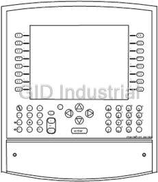
GE Fanuc MSDIS-1510 - Display 15.0" XGA, with Keypads and Touchscreen
Part Number
MSDIS-1510
Price
Request Quote
Manufacturer
GE FANUC
Lead Time
Request Quote
Category
Displays
Specifications
Display Type
TFT
Displays
All sizes
MTBF
35 million touches/spot
Native Colors
262,144
O/S driver availability
Windows 95/98, Windows NT
Resolution
4096 X 4096, >100,000 touch-points/sq. inch
XGA (1024 x 768)
Response time
100ms
Stylus
All types
Transmissivity
75%
Type
Analog Resistive
Datasheet

Extracted Text
GFK-1791
New In Stock!
GE Fanuc Manuals
http://www.pdfsupply.com/automation/ge-fanuc-manuals/operator-
interface/GFK-1791
operator-interface
1-919-535-3180
Marathon Series Industrial Computers and Monitors User’s
Man
www.pdfsupply.com
Email: sales@pdfsupply.com
GFK-1791
New In Stock!
GE Fanuc Manuals
http://www.pdfsupply.com/automation/ge-fanuc-manuals/operator-
interface/GFK-1791
operator-interface
1-919-535-3180
Marathon Series Industrial Computers and Monitors User’s
Man
www.pdfsupply.com
Email: sales@pdfsupply.com
GE Fanuc Automation
Industrial Computer Products
Marathon Series
Industrial Computers and Monitors
User's Manual
GFK-1791A April 2001
GFL-002
Warnings, Cautions, and Notes
as Used in this Publication
Warning
Warning notices are used in this publication to emphasize that hazardous voltages,
currents, temperatures, or other conditions that could cause personal injury exist in this
equipment or may be associated with its use.
In situations where inattention could cause either personal injury or damage to
equipment, a Warning notice is used.
Caution
Caution notices are used where equipment might be damaged if care is not taken.
Note: Notes merely call attention to information that is especially significant to understanding and
operating the equipment.
This document is based on information available at the time of its publication. While efforts
have been made to be accurate, the information contained herein does not purport to cover all
details or variations in hardware or software, nor to provide for every possible contingency in
connection with installation, operation, or maintenance. Features may be described herein
which are not present in all hardware and software systems. GE Fanuc Automation assumes no
obligation of notice to holders of this document with respect to changes subsequently made.
GE Fanuc Automation makes no representation or warranty, expressed, implied, or statutory
with respect to, and assumes no responsibility for the accuracy, completeness, sufficiency, or
usefulness of the information contained herein. No warranties of merchantability or fitness for
purpose shall apply.
The following are trademarks of GE Fanuc Automation North America, Inc.
Alarm Master Genius PROMACRO Series Six
CIMPLICITY Helpmate PowerMotion Series Three
CIMPLICITY 90–ADS Logicmaster PowerTRAC VersaMax
CIMSTAR Modelmaster Series 90 VersaPro
Field Control Motion Mate Series Five VuMaster
GEnet ProLoop Series One Workmaster
©Copyright 2000—2001 GE Fanuc Automation North America, Inc.
All Rights Reserved.
Contents
Chapter 1 Product Features ............................................................................................. 1-1
Innovative Modular Design ....................................................................................1-1
Factory Ready ........................................................................................................1-2
Connectivity...........................................................................................................1-2
Marathon Display Modules...........................................................................................1-3
Features..................................................................................................................1-3
Modular Simplicity.................................................................................................1-3
Rugged Touchscreens.............................................................................................1-4
Keypad Option .......................................................................................................1-4
Marathon Series CPU Module, Standard.......................................................................1-5
Marathon Series CPU Module, Expanded .....................................................................1-6
Single Board Computers ...............................................................................................1-7
SBC-Max-2 Features.............................................................................................. 1-7
SBC-PII Features....................................................................................................1-7
SBC-PII Single Board Computer Overview ............................................................1-8
SBC-PII Detailed Feature Description ....................................................................1-8
Marathon Series Monitor Video Electronics Module................................................... 1-10
Chapter 2 Marathon Monitors — Quick Install.............................................................. 2-1
Installing Marathon Display Modules ...........................................................................2-1
Installing the Marathon Monitor Video Electronics Module ..........................................2-2
Connecting the Marathon Video Electronics Module ..............................................2-2
Setting Video Resolution........................................................................................2-3
Switch Box Installation...........................................................................................2-4
Installing the Dynapro SC3 Driver................................................................................2-5
Calibrating the Dynapro SC3 Driver .............................................................................2-5
Monitor Adjustments ....................................................................................................2-6
Display Control Menus...........................................................................................2-6
Remove On Screen Display ....................................................................................2-7
Video Position Adjustment .....................................................................................2-7
Width.....................................................................................................................2-7
Brightness ..............................................................................................................2-7
Contrast..................................................................................................................2-8
Phase......................................................................................................................2-8
Zoom Enable..........................................................................................................2-8
Restore Factory Settings .........................................................................................2-8
Video Source..........................................................................................................2-8
Menu Position Adjustment .....................................................................................2-9
Menu Timeout........................................................................................................2-9
Status .....................................................................................................................2-9
GFK-1791A iii
Contents
Chapter 3 Marathon Computers — Quick Install .......................................................... 3-1
Installing Marathon Display Modules ...........................................................................3-1
Installing Marathon Computer (CPU) Modules .............................................................3-2
Power Connections .......................................................................................................3-3
Powering Up the Marathon Unit ...................................................................................3-3
Setting Up Windows 98 Systems ..................................................................................3-4
Setting Up Windows NT Systems .................................................................................3-4
Setting Screen Resolution .............................................................................................3-5
Calibrating the Touchscreen..........................................................................................3-6
Configuring the Marathon Computer to Run on a Microsoft Network............................3-6
Login Recommendation................................................................................................3-6
Chapter 4 Keypad and Connector Information .............................................................. 4-1
Keypads .......................................................................................................................4-1
Marathon 12" Display Keypad Assignments ...........................................................4-2
Marathon 15" Display Keypad Assignments ...........................................................4-3
Connectors ...................................................................................................................4-5
Front Access Panel .................................................................................................4-5
Communication Ports .............................................................................................4-5
ISA and PCI Expansion on the Marathon MSCPX CPUs ..............................................4-6
Chapter 5 BIOS Setup Guide........................................................................................... 5-1
Starting the BIOS Setup Utility.....................................................................................5-2
Navigating the Setup Menus .........................................................................................5-2
Legend Bar.............................................................................................................5-3
Field Help Window ................................................................................................5-3
General Help Window............................................................................................5-4
Main Menu...................................................................................................................5-5
Advanced Hard Disk Features.......................................................................................5-6
Advanced Menu............................................................................................................5-7
Integrated Peripherals.............................................................................................5-8
Security Control ................................................................................................... 5-11
Power Menu ............................................................................................................... 5-12
Boot Menu.................................................................................................................. 5-14
Exit Menu................................................................................................................... 5-15
Exit Saving Changes............................................................................................. 5-15
Exit Discarding Changes ...................................................................................... 5-15
Load Setup Defaults ............................................................................................. 5-16
Discard Changes................................................................................................... 5-16
Save Changes ....................................................................................................... 5-16
iv Marathon Series Industrial Computers and Monitors User's Manual–April 2001 GFK-1791A
Contents
Chapter 6 Technical Specifications.................................................................................. 6-1
CPU .............................................................................................................................6-1
Displays .......................................................................................................................6-1
Touchscreens................................................................................................................6-2
System DRAM .............................................................................................................6-2
System DRAM Installation (U3)...................................................................................6-2
Connectors ...................................................................................................................6-3
SBC-Max-2 Single Board Computer Connectors ....................................................6-3
PS/2 Mouse...........................................................................................................6-3
Keyboard Connector ............................................................................................. 6-3
USB Ports.............................................................................................................6-4
Serial Port Connector ............................................................................................6-4
Printer Port (LPT1) ...............................................................................................6-4
VGA Video Connector..........................................................................................6-5
Ethernet Port (E-NET) ..........................................................................................6-5
SBC-PII Single Board Computer Connectors..........................................................6-6
External Battery (J14) ...........................................................................................6-6
PS/2 Mouse Connector (J17).................................................................................6-6
Keyboard Interface (J27).......................................................................................6-6
USB Ports (J21)....................................................................................................6-8
Serial Port Interface (J18, J19, J24 and J25)...........................................................6-9
Serial Port Information........................................................................................ 6-10
SF12 Definition .................................................................................................. 6-10
Parallel Port (J20) ............................................................................................... 6-11
VGA Video Connector........................................................................................ 6-11
Ethernet (J10) ..................................................................................................... 6-12
Ethernet LEDs (J9) ............................................................................................. 6-12
Interrupt Assignments................................................................................................. 6-13
Chapter 7 Dimensions....................................................................................................... 7-1
12" Display, No Keypads, Standard Back CPU or Monitor Video Electronics Module7-2
12" Display, Keypads, Standard Back CPU or Monitor Video Electronics Module..7-3
12" Display, No Keypads, Expanded Back CPU.....................................................7-4
12" Display, Keypads, Expanded Back CPU...........................................................7-5
15" Display, No Keypads, Standard Back CPU or Monitor Video Electronics Module7-6
15" Display, Keypads, Standard Back CPU or Monitor Video Electronics Module..7-7
15" Display, No Keypads, Expanded Back CPU.....................................................7-8
15" Display, Keypads, Expanded Back CPU...........................................................7-9
18" Display, No Keypads, Standard Back CPU or Monitor Video Electronics Module7-10
18" Display, No Keypads, Expanded Back CPU................................................... 7-11
GFK-1791A Contents v
Product Features
Chapter
1
TM TM TM TM
A Marathon computer, with a Pentium , AMD , Celeron , or PIII processor, combined with
one of the many Marathon display options, can run virtually any application efficiently, crunching
through even the most complex algorithms at amazing speeds.
State-of-the-art panel mounting and connecting systems make it perfect for the shop floor or
control area. Built for harsh environments, a Marathon flat-panel computer will give you many
years of trouble-free service. Flexible and robust, Marathon computers make it easy for operators to
monitor and interact with machines and industrial processes. They give you the features you need
and connectivity that’s second to none. Because they’re open-system machines, they’ll easily
expand with your business.
Available in a full range of sizes, Marathon Flat Panel Displays offer an array of features and
options to complement their superior resolution and wide-angle visibility. Durable and sensitive
analog resistive touchscreens, and optional integrated membrane keypads increase the adaptability
of Marathon industrial monitors to your needs.
Innovative Modular Design
Marathon computers and monitors incorporate a unique modular design for quick installation that
dramatically reduces your downtime. You can connect the CPU module or Monitor Video
Electronics module to a Marathon Display package simply and easily. Because Marathon series
CPU modules work automatically with any size display, you can greatly reduce your spare parts
inventory costs. The modular design also allows for fast and easy future upgrades.
The following drawing shows a Marathon Display with a CPU module attached.
Marathon Display
A I
F1 F9
B J
F2 F10 Marathon CPU Module
C K
F3 F11
or
D L
F4 F12
E M
F5 F13 Monitor Video
F N
F6 F14
G O Electronics Module
F7 F15
H P
F8 F16
del Q R S
hom e ctr l
1 2 3
+
ta b T U V
print en d alt
- 4 5 6
up W X Y
shift spa ce
7 8 9
pa ge
* Z
shift bac k
lock esc spa ce
dow n .
enter = 0
/
marathon series
GFK-1791A 1-1
1
Factory Ready
Designed and built to withstand harsh, demanding environments, Marathon monitors are the perfect
tools for delivering information on the factory floor.
• Substantially smaller in size, they fit easier in any location
• Modular design allows for speedy installation and removal
• Increased reliability reduces downtime in your factory
• Lower power consumption rate means reduced operating costs and lower temperature
• Immunity to electromagnetic emissions, resistance to vibration, and a wider operational
temperature range enhance flexibility of placement
Connectivity
A Marathon series industrial computer is the ideal choice for plant floor communications. The CPU
module contains on-board Ethernet (10/100 Mbps), dual USB (Universal Serial Bus) ports, dual
RS-232 COM ports (one used by touchscreen) and an IrDA port so that you can connect without
the need for additional hardware.
1-2 Marathon Series Industrial Computers and Monitors User's Manual – April 2001 GFK-1791A
1
Marathon Display Modules
Combine a 12.1", 15", or 18.1" Marathon Display module with a CPU module to create an
industrial computer package. Combine a 12.1" or 15" Marathon Display module with a Monitor
Video Electronics module for a stand-alone industrial monitor. The Marathon Display module is
installed in the panel cutout with clips. The CPU module and the Monitor Video Electronics
module are installed on the Marathon Display module using clamps.
The following drawing shows a Marathon Display Module with a Monitor Video Electronics
module. The Video Electronics module has the same dimensions as the MSCPU computer module.
Panel
Marathon Display
A I
F1 F9
B J
F2 F10
Marathon Monitor
C K
F3 F11
Video Electronics
D L
F4 F12
Module
E M
F5 F13
F N
F6 F14
G O
F7 F15
H P
F8 F16
QR S
del
home ctrl
12 3
+
TU V
tab
print end alt -
4 56
WX Y
up
shift space
7 89
*
page Z
shift back
lock esc space .
down = 0
enter /
marathon series
Features
Displays 12.1" SVGA 800 x 600 pixels
15.0" XGA 1024 x 768 pixels
18.1" SXGA 1280 x 1024 pixels
High Performance Direct CRT replacement
Compatible with VESA compliant video signals
Analog Resistive touchscreen with serial output
Auto-sizing
Standard 15 pin VGA input
Optional function keypad
Front or side-accessible keyboard port
High Visibility TFT Active Matrix Color
Modular Simplicity
Unlike systems that require a specific PC bus video card, Marathon series flat-panel monitors with
state-of-the-art technology connect directly to your video sources using standard DB15 connectors.
This makes connecting our flat-panel monitors to such non-PC compatible platforms as VMEbus or
GFK-1791A Chapter 1 Product Features 1-3
1
Macintosh easy. For even greater convenience, you don't need a drill or screws to mount a
Marathon monitor in a panel—it simply clips in place.
Rugged Touchscreens
All Marathon displays come with a resistive touchscreen. Offering excellent durability and
resolution, resistive technology can be used in a wide variety of applications and environments. All
touchscreen Marathon series monitors come with high performance device drivers that enable the
touchscreen to emulate a mouse. They can operate with any application designed to run under
Windows™ 95/98, Windows NT™, or Windows 2000™. Resistive touchscreens allow operation
with gloved hands.
Keypad Option
The 12" and 15" Marathon Displays are available with integrated membrane keypads, making them
even more adaptable to your demanding applications. The membrane keypad option is not
available with the 18" Marathon display.
1-4 Marathon Series Industrial Computers and Monitors User's Manual – April 2001 GFK-1791A
1
Marathon Series CPU Module, Standard
The Standard CPU module contains a powerful CPU and all the support functions required for a
tough, industrial computer. The module can be connected to any of the Marathon displays, and is
easily attached or removed for maintenance.
Marathon Display
A I
F1 F9
Standard CPU Module
B J
F2 F10
C K
F3 F11
D L
F4 F12
E M
F5 F13
F N
F6 F14
G O
F7 F15
H P
F8 F16
QR S
del
home ctr l
+ 12 3
T UV
ta b
pri nt end alt - 4 56
WX Y
up
shift space
7 89
page *
Z
shift back .
lock esc space = 0
down enter /
marathon series
Monitor Package
Standard CPU
Module
GFK-1791A Chapter 1 Product Features 1-5
1
Marathon Series CPU Module, Expanded
The Expanded CPU module has the same features as the Standard CPU module with the addition of
two ISA expansion slots, two shared PCI/ISA expansion slots, and a CD-ROM. The module can be
connected to any of the Marathon displays, and is easily attached or removed for maintenance.
Marathon Display
A I
F1 F9
B J
Expanded CPU
F2 F10
C K
F3 F11
Module
D L
F4 F12
E M
F5 F13
F N
F6 F14
G O
F7 F15
H P
F8 F16
Q R S
del
home ctrl
+ 1 2 3
tab T U V
print end alt - 4 5 6
W X Y
up
space
shift
7 8 9
page * Z
shift back .
lock esc space down = 0
enter /
marathon series
Marathon Display
Expanded CPU
Module
1-6 Marathon Series Industrial Computers and Monitors User's Manual – April 2001 GFK-1791A
1
Single Board Computers
SBC-Max-2 Features
Processor Pentium MMX or AMD-K6-2
Memory 64 MB, 128 MB
BIOS Phoenix
L2 Cache 512K
Drives 4GB or greater IDE hard drive
1.44 MB floppy, front accessible
Screen Drivers Windows 98 or Windows NT
Ports 10/100 Base-T Ethernet (RJ-45)
Two USB
Two RS-232 serial ports (One used for touchscreen)
One Parallel, DB-25 Centronix compatible
One VGA, DB-15 output
One IrDA, Full Duplex
One PS/2 Keyboard port, front or side access
One PS/2 Mouse port, front or side access
Operating Systems Windows 98, Windows NT, or Windows 2000
Power Supply 110-240VAC, 50-60Hz, 100W (@ 50°C supply only)
SBC-PII Features
Processor Celeron or PIII
Memory 64 MB, 128 MB, or 256 MB
Expansion Slots Two ISA, two shared PCI/ISA
BIOS Phoenix BIOS
L2 Cache 512KB (Celeron 128KB)
Drives 4GB or greater IDE hard drive
1.44 MB floppy, front accessible
CD-ROM, front accessible, R/W CD-ROM available with PIII processors
Screen Drivers Windows 98, Windows NT, or Windows 2000
Ports 10/100 Base-T Ethernet (RJ-45)
Two USB
Two RS-232 serial ports (one used for touchscreen)
One parallel, DB-25 Centronix compatible
One VGA, DB-15 output
One IrDA, Full Duplex
One PS/2 Keyboard port, front or side access
One PS/2 Mouse port, front or side access
Operating Systems Windows 98, Windows NT, or Windows 2000
Power Supply 110-240VAC, 50-60Hz, 100W (@ 50°C supply only)
GFK-1791A Chapter 1 Product Features 1-7
1
SBC-PII Single Board Computer Overview
The SBC-PII is an industrial-design single board computer with all the functionality of today’s best
desktop Intel Celeron and PIII machines. Its standard features include a Celeron or PIII CPU,
Accelerated Graphics Port (AGP) video controller, 10/100BaseT Ethernet, and USB ports.
The SBC-PII provides leading edge flat panel support, including GUI Accelerator and Multimedia
Engine especially for the newer color TFT LCDs. This 64-bit AGP chip includes up to 4Mbytes
SDRAM video memory for maximum color depth in all resolutions and operating systems. The
CT69000 also supports YUV and NTSC input with RGB conversion for CRT and provides display
centering and stretching features for optimal presentation of VGA graphics and text on 800x600
and 1024x768 panels.
The SBC-PII memory and storage options start with 8Mbytes DRAM and up to 256 Mbytes with
one double sided non-registered DIMM. The IDE hard disk interface supports up to four IDE
(ATA/ATAPI) drives. The floppy disk controller supports two 1.44Mbyte or 2.88Mbyte floppy
drives.
Other I/O features include two USB ports for extra peripheral interfaces, up to four serial ports (one
with IrDA interface), slot or header option, a printer port, plus standard keyboard header, PS/2
mouse and PC speaker. Advanced power management with timed power down, wake-up on LAN,
PS/2 mouse or Keyboard triggers. Completing the list of features is PCI/ISA bus expansion using a
PISA option card.
SBC-PII Detailed Feature Description
Processor Intel PIII available with 700MHz or above core frequencies with 512KB level
two cache or Intel Celeron with 566MHz or above core frequencies with 128
KB level-two cache.
Binary compatible with applications running on previous members of the Intel
microprocessor line
DRAM controller SDRAM from 8 to 128 Mbytes or 256 Mbytes (with non-registered DIMMs)
Up to one double-sided DIMM (2 rows memory)
PCI bus interface PCI Rev. 2.1, 3.3V and 5V, 33MHz interface compliant
Power Management Functions Stop Clock Grant and Halt special cycle translation (host to PCI Bus)
Dynamic power down of idle SDRAM rows
Independent, internal dynamic clock gating reduces average power dissipation
DPMS for CRT power-down (required for support of EPA Energy-Star
program)
DDC for CRT Plug-Play & Display Control
Supports LAN, PS/2 or keyboard wake up functions
Integrated IDE Controller Independent Timing of Up to 4 Drives
Front Panel Connector providing access to hardware Reset and IDE activity
LED
Enhanced DMA Controller
System Timer, Refresh Request, Speaker Tone Output
USB Two USB Ports for Serial Transfers at 1.5 or 12 Mbit/sec per UHCI Revision
1.1
SMBus Host interface Allows CPU to Communicate via SMBus
Slave Interface Allows External SMBus Master to Control Resume Events
1-8 Marathon Series Industrial Computers and Monitors User's Manual – April 2001 GFK-1791A
1
Real-Time Clock 256-Byte Battery-Back CMOS SRAM
Multimedia Flat Panel/CRT GUI Highly integrated design Flat Panel and CRT GUI Accelerator & Multimedia
Accelerator Engine, Palette/DAC, and Clock Synthesizer
Hardware Windows Acceleration
— Transparent System-to-Screen and Screen-to-Screen BitBLT
— 8/16/24 Color Expansion
— Optimized for Windows BitBLT format
High Performance deep write buffers
170 MHz RAMDAC
Hardware Multimedia Support — YUV input from System Bus or Video Port
— Capture / Scaling, Video Zoom up to 8x
Display centering and stretching features for optimal fit of VGA graphics and
text on 800x600 and 1024x768 panels
Optimized for High-Performance Flat Panel Display at 3.3V and 5V — 640 x
480 x 24bpp to 1280 x 1024 x 24bpp
Flexible On-chip Activity Timer facilitates ordered shutdown of the display
system
Fully Compatible with IBM VGA
Super I/O PC97 compliant hardware
2.88MB floppy disk controller, supports two 360K / 720K / 1.2M /
1.44M/2.88M floppy disk drives
Multi-mode high performance parallel port
Serial ports – four 16C550 compatible, enhanced RS-232 ports, support SIR or
ASKIR IrDA
Keyboard Controller — Standard keyboard and PS/2 mouse
Ethernet Supports 10 Mb/s and 100 Mb/s N-way auto-negotiation
Supports Full duplex flow control (IEEE 802.3x)
LED interface for network activity indications
PC Expansion Supports PCI - ISA expansion board
Monitoring Fan Monitor
Power Supply Monitor
Flash drive Disk on a Chip — Up to 144Mbytes
Compact Flash/ATA
GFK-1791A Chapter 1 Product Features 1-9
1
Marathon Series Monitor Video Electronics Module
Add the Marathon Monitor Video Electronics Module to a Display package for a stand-alone
industrial monitor. The following drawing shows a Marathon Product configured as a stand-alone
industrial monitor.
The MSMON-00 Video Electronics package is used with 12.1", and 15" displays.
Panel
Marathon Display
A I
F1 F9
B J
F2 F10
Marathon Monitor
C K
F3 F11
Video Electronics
D L
F4 F12
Module
E M
F5 F13
F N
F6 F14
G O
F7 F15
H P
F8 F16
QR S
del
home ctrl
12 3
+
TU V
tab
print end alt
- 4 56
WX Y
up
shift space
7 89
page *
Z
shift back
esc .
lock space 0
down enter / =
marathon series
1-10 Marathon Series Industrial Computers and Monitors User's Manual – April 2001 GFK-1791A
Marathon Monitors — Quick Install
Chapter
2
A Marathon Industrial Monitor consists of two components: a Marathon display, and a Marathon
Monitor Video Electronics module. The installation process is simple. Make a cutout in the panel,
clip the Display module in place, then attach the Marathon Monitor Video Electronics module to
the display package using the built-in quarter-turn clamps. If you have questions during the
installation process you can contact our technical support group at 1-800-433-2682.
All Marathon Industrial Monitor products are fully compatible with VESA compliant Video
signals.
Installing Marathon Display Modules
Each Marathon Display is assigned a model number, based on the display size and whether it has
the optional keypad.
MSDIS-1200 12.1" SVGA, Touchscreen
MSDIS-1210 12.1" SVGA, with Keypads and Touchscreen
MSDIS-1500 15.0" XGA, Touchscreen
MSDIS-1510 15.0" XGA, with Keypads and Touchscreen
To determine the correct panel cutout, note the model number on your display and match the
dimension drawing in chapter 7 of this manual with your display. Copy the panel cutout
dimensions to your panel and mark the panel cutout hole. After cutting the hole, insert the display
in the cutout and attach the mounting clips to the notches along the sides of the display housing.
Tighten the clips and you are done with the display installation.
Mounting Clips
GFK-1791A 2-1
2
Installing the Marathon Monitor Video Electronics Module
The next step in the installation of a Marathon Industrial Monitor is to mount the Monitor Video
Electronics module to the back of the display module. The MSMON-00 Monitor Video Electronics
module is used with 12.1", and 15" displays.
Align the Marathon Monitor Video Electronics Module with the opening in the back of the display
module. Four mounting clamps are used to secure the video package to the display package. Turn
the screws in the mounting clamps to secure.
Panel
Mounting Clamps
Connecting the Marathon Video Electronics Module
1. Connect a VGA Cable from your computer to the Marathon Video Electronics Module Video
port. The following drawing shows the connector panel on the Marathon Video Electronics
Module.
KYBRD
OUT
VIDEO COM SWITCHES
KYBRD
IN
.
2 If you are using the touchscreen, connect the serial port from your computer to the COM port
on the Marathon Video Electronics Module and load the touchscreen driver on your computer
using the provided Touchscreen driver disk. Refer to “Dynapro SC3 Driver Installation.” You
will need to calibrate the touchscreen after driver installation. For calibration refer to
“Calibrating Dynapro SC3 Drivers.”
3. If you are using a Keypad or external keyboard you must connect the keyboard port from your
computer to the KYBRD OUT port on the Marathon Video Electronics Module.
2-2 Marathon Series Industrial Computers and Monitors User's Manual – April 2001 GFK-1791A
2
4. Connect your keyboard (if used) to either the front-access PS/2 port on the front of your
marathon display or to the KYBRD IN port on the Marathon Video Electronics module. Both
the front access port and the side access keyboard ports may not be used simultaneously.
5. Connect power. Power connections are made to a terminal strip located on the side of the unit.
To access the terminal strip, remove the rear cover. The power supply is rated at 110 -
240VAC, 50 - 60Hz, 100W@50°C. Note the terminal markings for Line (L), Ground (G), and
Neutral (N).
Power Terminals
Cover Screws
6. Because the Marathon Monitors have the ability to connect to a variety of VESA compliant
computer devices, the unit must be configured prior to being used. The “Monitor
Adjustments” section describes the configuration process.
Setting Video Resolution
You may need to optimize the video resolution of your computer to match the Marathon Monitor.
When operating in a 640 x 480 mode on a display with higher resolution capability the image will
not occupy the full screen. When operating in a resolution larger than the Marathon monitor you
purchased; the image may not be legible. The On-Screen Display, outlined in the Monitor
Adjustment section, will display the video signal’s resolution in the bottom center of the display
area. To optimize your image you will need to set the screen resolution using the following
instructions:
1. From the Windows Task Bar select the “Settings” icon.
2. Select the Control Panel.
3. Select Display.
4. Select the Settings tab.
GFK-1791A Chapter 2 Marathon Monitors — Quick Install 2-3
2
5. In the box labeled Desktop Area select the proper resolution for your Marathon Display using
the table below:
Model # Screen Resolution
MSDIS-1200/1210 800 x 600
MSDIS-1500/1510 1024 x 768
6. Click the Test button to verify that the changes you have selected are working properly.
7. After the 5 second test mode has completed, click OK, followed by the Apply button. Your
display should now be set up properly.
Switch Box Installation
1. Locate the SWITCHES connector on the Marathon Monitor Video Electronics Module and
connect the cable from the switch box to the port.
2. Press the FCTN key to display the On-Screen-Display (OSD) menu.
The switch box contains firmware that monitors switch activity and responds accordingly. The
OSD menus provide visual confirmation of selections and adjustments by highlighting selections
and modifying on-screen bar-graph levels.
The Video Electronics module is initialized during power-on to the last known saved conditions.
All parameters are saved when you exit the menus, or by a sixty second time out.
2-4 Marathon Series Industrial Computers and Monitors User's Manual – April 2001 GFK-1791A
2
Installing the Dynapro SC3 Driver
1. Insert Dynapro SC3 Driver disk into your computer's floppy drive.
.
2 Run A:\INSTALL.EXE.
Driver and Path verification screen: These settings are not modifiable. They are for
verifying the driver and version that is being installed. Click Next.
Configuration Screen: For MSDIS, MSMON combination - change COM Port to that which
the DB9 cable is attached to on the PC. Verify IRQ and I/O address are those that are defined
in CMOS. Click Next.
Install Parameter Summary Screen: Verify settings are correct.
3. Click Install.
4. After installation is complete, restart Windows for the changes to take effect by clicking “Yes”
when prompted.
5. Remove floppy disk while system is rebooting.
.
6 Cursor may not respond correctly to touches after system has finished booting for the first
time.
7. Run Driver Configuration as described in “Calibrating the Dynapro SC3 Driver.”
Calibrating the Dynapro SC3 Driver
Note: The cursor may not respond to the touchscreen correctly after
system has finished booting for the first time.
1. Run Start – Programs – Touch Screen Utilities – Configuration.
2. Click “Interface…”
3. Click “Advanced…”
4. Change “Screen Wires:” from 4 to 8 using the pulldown menu.
5. Click “OK” to exit Advanced Controller Option.
6. Click “OK” to exit Interface Configuration Options.
7. Choose “Calibration…” on Configuration Utilities Screen.
8. Choose “Calibrate”
9. Touch the three targets as they appear on the screen, the first in the upper left corner, the
second in the lower right, and the third in the middle right.
10. Click “OK” to exit calibration screen.
.
11 Click “Exit” to close Configuration Utility.
GFK-1791A Chapter 2 Marathon Monitors — Quick Install 2-5
2
Monitor Adjustments
An on-board micro-controller in the Marathon Video Electronics module provides main system
control, system initialization, input mode auto-detection, and a user interface for monitor
adjustments. An external switch box is connected to the user interface port (SWITCHES) and
allows the user to make all monitor display adjustments.
The external switch box layout is shown in the drawing below.
UP BUTTON RIGHT BUTTON
LEFT
BUTTON
RESERVED
FCTN
DOWN BUTTON MENU/EXIT BUTTON
The switch box buttons provide the following selection functions:
FCTN Activate Input Select Menu, exit all menus
LEFT Decrease selected parameter value
RIGHT Increase selected parameter value
Position Display image
UP
DOWN Position Display image
Display Control Menus
The On-Screen Display (OSD) menu appears when the FCTN key is pressed on the external switch
box. The ‘LEFT’ and ‘RIGHT’ keys highlight the desired parameter and adjust the
parameter value. The and keys are used to move between the upper and lower row of icons
on the display. The displayed bar graph indicates the relative level for each parameter. To exit the
Display Control menu, press the FCTN key.
M E N U
R e m o v e O S D
6 4 0 x 4 8 0
Not making a selection or adjustment within sixty seconds of activating the Display Control menu
will result in the system exiting from the menu.
2-6 Marathon Series Industrial Computers and Monitors User's Manual – April 2001 GFK-1791A
2
Remove On Screen Display
This menu selection allows the manual removal of the On Screen Display
from the Panel. Press the or keys on the keypad to select the icon,
then press FCTN to begin this command.
Video Position Adjustment
This menu selection allows the adjustment of the picture on the Panel.
Press the or keys on the keypad to select the icon, then press FCTN
to begin this command.
The or keys are used to center the image horizontally on the display by moving the input
image capture window left or right. The and keys are used to center the image vertically on
the display by moving the input image capture window up or down. The image window may be
moved anywhere in the input frame except within the V-sync period.
Width
This menu selection allows the adjustment of the horizontal width of the
picture on the Panel. Press the or keys on the keypad to select the
icon, then press FCTN to begin this command.
The or keys are used to adjust the display image to fill the panel horizontally. A scroll bar
will appear on the display to indicate the relative setting.
M E N U
Wid t h 12 7
6 4 0 x 4 8 0
Brightness
The Brightness control adjusts the brightness level of the input source. Press the
or arrow keys on the keypad to select the icon, then press FCTN to begin this
command.
The or keys are used to adjust the display image to the viewing preference of the user. A
scroll bar will appear on the display to indicate the relative setting.
GFK-1791A Chapter 2 Marathon Monitors — Quick Install 2-7
2
Contrast
The Contrast control adjusts the contrast ratio of the input source +/-3dB from the
nominal 0.714V. Press the or keys on the keypad to select the icon, then press
FCTN to begin this command.
The or keys are used to adjust the display image to the viewing preference of the user. A
scroll bar will appear on the display to indicate the relative setting.
Phase
The ADC Clock Phase adjustment is available for PC Graphics inputs only. Phase
adjust alters the sub-pixel sampling (fine pixel adjust). The phase of the ADC sample
pixel clock may be adjusted from 0 to 360 degrees for PC Graphics inputs.
Press the or keys on the keypad to select the icon, then press FCTN to begin this command.
The or keys are used to adjust the display for the clearest image. A poor adjustment is
indicated by horizontal streaks on a 50% grey background. There may be several levels where no
change is noticeable. Leave the adjustment in the center of this stable region. A scroll bar will
appear on the display to indicate the relative setting.
Zoom Enable
This function toggles the Zoom feature of the Marathon Video Display
Module. With Zoom disabled, a video resolution lower than the maximum
the panel supports, will fill only a portion of the whole screen. With Zoom
enabled, the Marathon Video Electronics Module will stretch the lower video resolution image to
fill the display screen. Press the or keys on the keypad to select the icon, then press FCTN
to toggle this feature.
Restore Factory Settings
Press the or keys on the keypad to select the icon, then press FCTN to
select this feature. This will reset all Display Control menu parameters to
their FACTORY DEFAULT settings.
Video Source
Press the or keys on the keypad to select the icon, then press FCTN to select
this feature. The Input Select Menu will appear when the Marathon Video
Electronics Module is properly connected and powered up.
The or keys select which input will be displayed if multiple inputs are connected. The
selections are: RGB (PC Graphics), YUV (Composite Video), or manual. Select RGB” (PC
Graphics) for proper operation of the Monitor Video Electronics Module. Not making a selection
within sixty seconds of activating the menu will result in the system exiting from the menu. A
2-8 Marathon Series Industrial Computers and Monitors User's Manual – April 2001 GFK-1791A
2
change in resolution of the selected input source will be detected within one second of obtaining
valid source timing.
MENU
P r i o r i t y : m a n u a l
V i d e o S o u r c e : R G B
6 4 0 x 4 8 0
Menu Position Adjustment
Press the or keys on the keypad to select the icon, then press FCTN
to select this feature. ME N U
The or keys are used to move the OSD horizontally on the display.
The and keys are used to move the image vertically on the display.
Menu Timeout
Menu Timeout allows adjustment of the length of time the menu will be
displayed before it is automatically removed from the display. Press the or
keys on the keypad to select the icon, then press FCTN to select this feature.
The or keys are used to decrease or increase the length of time the OSD is displayed. A
scroll bar will appear on the display to indicate the relative setting.
Status
The Status display includes the Resolution, Refresh Frequency and Number of Lines
displayed.
Press the or keys on the keypad to select the icon, then press FCTN to select this display.
M E N U
52 5 l i n e s H- V -
60 . 0 1 h z DS S
6 4 0 x 4 8 0
GFK-1791A Chapter 2 Marathon Monitors — Quick Install 2-9
Marathon Computers — Quick Install
Chapter
3
A Marathon industrial computer consists of two components: a Marathon Display, and a Marathon
Computer module. The installation process is simple. Make a cutout in the panel, clip the display in
place, then attach the Marathon Computer module to the display package using the built-in quarter-
turn clamps.
If you have questions during the installation process, contact our technical support group at
1-800-433-2682.
Installing Marathon Display Modules
Each Marathon Display is assigned a model number, based on the display size and whether it has
the optional keypad.
MSDIS-1200 12.1" SVGA, Touchscreen
MSDIS-1210 12.1" SVGA, with Keypads and Touchscreen
MSDIS-1500 15.0" XGA, Touchscreen
MSDIS-1510 15.0" XGA, with Keypads and Touchscreen
MSDIS-1800 18.1" SXGA, Touchscreen
To determine the correct panel cutout, note the model number on your display and match the
dimension drawing in chapter 7 of this manual with your display. Copy the panel cutout
dimensions to your panel and mark the panel cutout hole. After cutting the hole, insert the display
in the cutout and attach the mounting clips to the notches along the sides of the display housing.
Tighten the clips and you are done with the display installation.
Mounting Clips
GFK-1791A 3-1
3
Installing Marathon Computer (CPU) Modules
Each Computer module is assigned a model number, based on various options. You can order the
Standard (MSCPU) or Expanded back (MSCPX), different CPU/RAM/HD options, and different
operating systems.
Align the Computer module with the opening in the back of the monitor display package. Four
mounting clamps are used to secure the Computer module to the display package. Turn the screws
in the mounting clamps to secure the Computer module.
Panel
Mounting Clamps
Mounting Clamps
3-2 Marathon Series Industrial Computers and Monitors User's Manual – April 2001 GFK-1791A
3
Power Connections
Power connections are made to a terminal strip located on the side of the unit. To access the
terminal strip, remove the rear cover. The power supply is rated at 110 - 240VAC, 50 - 60Hz,
100W @ 50°C. Note the terminal markings for Line (L), Ground (G), and Neutral (N).
Power Terminals
Cover Screws
Powering Up the Marathon Unit
Caution
Do not connect or disconnect external devices, such as a printer or a PS/2
mouse or keyboard, while the unit is powered. Failure to observe this
precaution could result in damage to the equipment.
Note: During power up, the processor will run its normal diagnostic checks and indicate
the presence of any errors either with a screen prompt or with warning beeps.
GFK-1791A Chapter 3 Marathon Computers — Quick Install 3-3
3
Setting Up Windows 98 Systems
Before you get started, you need a PS/2 keyboard. A PS/2 mouse is also recommended to help
navigate through the setup screens.
1. Plug in the keyboard, PS/2 mouse (if available), and power cord.
2. Power on the unit. The Windows 98 Setup screen will appear.
3. Type your name.
4. Press the Tab key and type your company name
5. Press Enter.
6. Read the license agreement
7. Click your choice.
8. Click Next.
9. Enter the Windows 98 Certificate of Authenticity number found on the front of your
Windows 98 manual. Press Enter.
10. The network card used in these systems supports Plug & Play installation.
.
11 Windows 98 will go through setup.
12. When prompted for Date/Time Properties, use your left and right arrow keys to set the time
zone to your time zone. Press Enter.
13. If you have a printer connected, click Next and select your printer model type. If not, click the
Cancel button. The Welcome to Windows 98 window will appear.
.
14 Click Close for the Welcome to Windows 98 window.
Setting Up Windows NT Systems
Before you get started, you need a PS/2 keyboard. A PS/2 mouse is recommended to help navigate
through the setup screens.
1. Plug in the keyboard, PS/2 mouse (if available), and power cord.
2. Power on the unit.
3. Read license agreement
4. Tab to your choice and press Enter.
5. Press Enter to start the Windows NT Setup.
6. Type your name
7. Press the Tab key and type your company name.
8. Press Enter.
3-4 Marathon Series Industrial Computers and Monitors User's Manual – April 2001 GFK-1791A
3
9. Enter your Windows NT Authentication number found on your Windows NT manual. You
will need to use the Tab key to get to each number field. If correct, press Enter.
10. Enter a Computer name. This name should be unique to other computers on the same network.
Press Enter. You will be prompted for a password.
Note: Your system has been set up to enable autologon. Autologon allows the system to
boot into Windows NT without your having to use a keyboard to press
Ctrl-Alt-Del.
11. To use the autologon feature, type admin for the password. Press the Tab key and type admin
in the Confirm Password box. Press Enter. (To skip the password, press Enter.)
12. To assign a password, type in a password, press the Tab key, and type the password in the
Confirm Password box. Press Enter.
13. Press Enter to continue with Windows NT Setup.
14. Click "Finish."
Setting Screen Resolution
When the Marathon computer is shipped it is configured for 640 x 480 resolution to allow it to
operate with any of the Marathon Displays. When using the 640 x 480 mode on a display with
higher resolution capability the image will not occupy the full screen. To resolve this issue you
will need to set the screen resolution using the following instructions:
1. From the Windows Task Bar select the “Settings” icon.
2. Select the “Control Panel”
3. Select “Display”
4. Select the “Settings” Tab
5. In the box labeled “Desktop area” select the proper resolution for your Marathon Display
which using the table below:
Model # Screen Resolution
MSDIS-1200/1201/1210/1211 800 x 600
MSDIS-1500/1510 1024 x 768
MSDIS-1800 1280 x 1024
6. Click the test button to verify that the changes you have selected are working properly.
7. After the 5 second test mode has completed, click “OK”, followed by the “Apply” button.
Your display should now be set up properly.
GFK-1791A Chapter 3 Marathon Computers — Quick Install 3-5
3
Calibrating the Touchscreen
The first time you Power on the Marathon Computer you will need to calibrate the touchscreen
using the steps listed below:
1. From the Windows taskbar select Programs.
2. Select Touch Screen Utilities.
3. Select Calibrate and follow the directions on your screen.
Configuring the Marathon Computer to Run on a Microsoft Network
Before setting up your new Marathon Computer for the network, you should consult with your
network administrator. Duplicate TCP/IP addresses and duplicate computer names on the same
network can cause network problems.
1. Click the Start icon, then click Settings and Control Panel.
2. In the Control Panel window, double click the Network icon. The Network dialog box will
appear.
3. In the Network dialog box, click the Identification tab. You will need to type in your Computer
name, Workgroup name, and Computer Description.
4. To allow sharing,
A. Go to the Configuration tab and click the File and Print Sharing button. The File and Print
Sharing dialog box will appear.
B. Check the File and Print Sharing options that you want and click OK.
5. To add the TCP/IP protocol,
A. Go to the Configuration tab and click the Add button. The Select Network Component
dialog box will appear.
B. Click the Protocol icon and click Add. The Select Network Protocol dialog box will
appear.
C. In the Manufacturer list, select Microsoft. In the Protocol list, select TCP/IP. Click OK.
D. Change the Address from 10.0.0.1 to a unique address. Change the default subnet mask
255.0.0.0 to your subnet mask.
E. Click OK twice.
6. When you have finished setting up the Network, click OK in the Network dialog box. Click
Yes to reboot your system now.
Login Recommendation
If you type admin as your Administrator password, you will automatically log on as Administrator.
3-6 Marathon Series Industrial Computers and Monitors User's Manual – April 2001 GFK-1791A
Keypad and Connector Information
Chapter
4
Keypads
When you select the optional integrated membrane keypad for the 12" or 15" display, the display is
surrounded with keypads that emulate PC style keyboard keys. Many of the keypads have multiple
character sets along with their default functions.
The keypads for the 12" displays are configured differently from the keypads for the 15" display.
The keypads are divided into operational groups. The first group are the Function keys. The
example below is the F1 key. Pressing the key produces the code equivalent to F1. Pressing the
SHIFT key changes the character set to lower case alpha, so that when the F1 key is pressed, the
lower case 'a' is produced. Pressing the SHIFT LOCK key changes the character set to upper case
alpha, so that when the F1 key is pressed, the upper case 'A' is produced. See the Keypad
Assignment tables, listed in “Marathon 12" Keypad Assignments” (page 4-2) and “Marathon 15"
Keypad Assignments” (page 4-3) for all the key and corresponding code assignments.
A
F1
Notes
• SHIFT LOCK A toggle button. When pressed, it turns on the SHIFT LOCK LED, enables the upper
case alpha character set, and turns off SHIFT if it was previously enabled. When it is
pressed off, the SHIFT LOCK LED is turned off and the upper case alpha character set
is disabled.
A toggle button. When pressed, it turns on the SHIFT LED, enables the lower case
• SHIFT
alpha character set, and turns off SHIFT LOCK if it was previously enabled. When it is
pressed off, the SHIFT LED is turned off and the lower case alpha character set is
disabled.
Emulates the standard PC ALT key to modify the currently active character set. This
• ALT
key must be held at the same time as the second key.
• Emulates the standard PC CTRL key to modify the currently active character set. This
CTRL
key must be held at the same time as the second key.
GFK-1791A 4-1
4
Marathon 12" Display Keypad Assignments
Default Upper Case Alpha Lower Case Alpha
[Field reconfigurable] Character Set Character Set
F1 A A
F2 B B
F3 C C
F4 D D
F5 E E
F6 F F
F7 G G
F8 H H
F9 I I
F10 J J
F11 K K
F12 L L
ALT-CTRL-F3 [F13] M M
ALT-CTRL-F4 [F14] N N
ALT-CTRL-F5 [F15] O O
ALT-CTRL-F6 [F16] P P
1Q Q
2R R
3S S
4T T
5U U
6V V
7W W
8X X
9Y Y
= (equal) Z Z
00 0
. (Period) . (Period) . (Period)
+ (Plus) + (Plus) + (Plus)
- (Dash) - (Dash) - (Dash)
* (Asterisk) * (Asterisk) * (Asterisk)
/ (Forward Slash) / (Forward Slash) / (Forward Slash)
BACKSLASH BACKSLASH BACKSLASH
HOME HOME HOME
CTRL CTRL CTRL
(See “Notes,” p. 4-1) (See “Notes,” p. 4-1) (See “Notes,” p. 4-1)
PRINT PRINT PRINT
END END END
ALT ALT ALT
(See “Notes,” p. 4-1) (See “Notes,” p. 4-1) (See “Notes,” p. 4-1)
4-2 Marathon Series Industrial Computers and Monitors User's Manual – April 2001 GFK-1791A
4
Default Upper Case Alpha Lower Case Alpha
[Field reconfigurable] Character Set Character Set
SHIFT (Toggle) (See Shift Toggle Shift Toggle
“Notes,” p. 4-1)
DECIMAL DECIMAL DECIMAL
SPACE SPACE SPACE
SHIFT LOCK (See “Notes,” SHIFT LOCK SHIFT LOCK
p. 4-1)
ESC ESC ESC
BKSPACE BKSPACE BKSPACE
DELETE DELETE DELETE
TAB TAB TAB
Pg Down Pg Down Pg Down
Pg Up Pg Up Pg Up
Up Arrow Up Arrow Up Arrow
Down Arrow Down Arrow Down Arrow
Left Arrow Left Arrow Left Arrow
Right Arrow Right Arrow Right Arrow
ENTER ENTER ENTER
Marathon 15" Display Keypad Assignments
Default Upper Case Alpha Lower Case Alpha
[Field reconfigurable] Character Set Character Set
F1 A A
F2 B B
F3 C C
F4 D D
F5 E E
F6 F F
F7 G G
F8 H H
F9 I I
F10 J J
F11 K K
F12 L L
ALT-CTRL-F3 [F13] M M
ALT-CTRL-F4 [F14] N N
ALT-CTRL-F5 [F15] O O
ALT-CTRL-F6 [F16] P P
ALT-CTRL-F7 [F17] Q Q
ALT-CTRL-F8 [F18] R R
ALT-CTRL-F9 [F19] S S
ALT-CTRL-F10 [F20] T T
GFK-1791A Chapter 4 Keypad and Connector Information 4-3
4
Default Upper Case Alpha Lower Case Alpha
[Field reconfigurable] Character Set Character Set
1U U
2V V
3W W
4X X
5Y Y
6Z Z
77 7
88 8
99 9
00 0
== =
. (Period) . (Period) . (Period)
+ (Plus) + (Plus) + (Plus)
- (Dash) - (Dash) - (Dash)
* (Asterisk) * (Asterisk) * (Asterisk)
/ (Forward Slash) / (Forward Slash) / (Forward Slash)
36
\ (Back Slash) \ (Back Slash) \ (Back Slash)
HOME HOME HOME
CTRL CTRL CTRL
(See “Notes,” p. 4-1) (See “Notes,” p. 4-1) (See “Notes,” p. 4-1)
PRINT PRINT PRINT
END END END
ALT ALT ALT
(See “Notes,” p. 4-1) (See “Notes,” p. 4-1) (See “Notes,” p. 4-1)
SHIFT (Toggle) (See SHIFT SHIFT
“Notes,” p. 4-1)
PERIOD PERIOD PERIOD
SPACE SPACE SPACE
SHIFT LOCK (See “Notes,” SHIFT LOCK SHIFT LOCK
p. 4-1)
ESC ESC ESC
BKSPACE BKSPACE BKSPACE
DELETE DELETE DELETE
TAB TAB TAB
Pg Down Pg Down Pg Down
Pg Up Pg Up Pg Up
Up Arrow Up Arrow Up Arrow
Down Arrow Down Arrow Down Arrow
Left Arrow Left Arrow Left Arrow
Right Arrow Right Arrow Right Arrow
ENTER ENTER ENTER
20
4-4 Marathon Series Industrial Computers and Monitors User's Manual – April 2001 GFK-1791A
4
Connectors
Caution
External devices (printer, external disk drive etc.) should not be connected
or disconnected from the industrial computer when the unit is powered up.
Front Access Panel
The front access panel provides easy access to peripherals. The peripherals which are front
accessible depend on which Marathon product you have purchased. On the Marathon MSCPX
expanded CPU products, you have access to a floppy disk drive, the mouse and keyboard ports, and
a CD-ROM drive. On the MSCPU standard CPUs, you have access to a floppy disk drive and the
mouse and keyboard ports. The Marathon MSMON products only allow access to the keyboard
port. To open the access panel, loosen the two thumbscrews on the cover.
IRDA
Keyboard
Floppy Disk Mouse CD-ROM (Optional)
Communication Ports
All of the communication ports are accessible from the side of the unit. The Mouse and Keyboard
ports are also located behind the front access panel.
USB
Keyboard
Mouse
COM1
Printer
(LPT)
Video
Ethernet
GFK-1791A Chapter 4 Keypad and Connector Information 4-5
1 - MOUSE
2 - KYBRD
1
USB
LPT1
E-NET VIDEO COM 1
2
4
Connector Description
VGA Video Connector VGA, DB-15 output. A VGA monitor can be
connected to the Marathon Computer products if an
external monitor is required during the development
process. This option is not available on the Marathon
Monitor products.
Serial Port Connector The Marathon MSCPU and MSCPX products have
one RS-232 serial port (COM 1) available on the side
of the computer module. The second serial port is
used for the touchscreen and is not available for the
user.
Printer Port (LPT1) Parallel, DB-25 Centronix compatible.
USB Ports Two industry standard USB ports.
Keyboard Connector Industry standard PS/2 keyboard connector.
PS/2 Mouse Industry standard PS/2 mouse connector.
IrDA (Infrared Data Association) Port The IrDA port interfaces with an optical module for
wireless communication with other IrDA devices.
The IrDA LEDs are accessible from the front access
door on the MSDIS Marathon displays. The IrDA
port is only available when the Marathon display
module is connected to an MSCPU or MSCPX
Marathon CPU. This option is not available when
using an MSMON Monitor Video Electronics
Module.
Ethernet Port (E-NET) Industry standard RJ-45 port for 10/100baseT
Ethernet.
Note: For pinouts, refer to "Connectors" in Chapter 6.
ISA and PCI Expansion on the Marathon MSCPX CPUs
Before applying power to your Marathon computer you will need to install any PCI or ISA cards
required for your application. The Marathon MSCPX Expanded CPU backplane has two slots
dedicated to ISA expansion cards and two slots that can be used for either ISA or PCI cards.
To install cards, remove the back cover from the MSCPX CPU module by removing the five thumb
screws. Once you have removed the cover, remove the blank orbs for the slots in which you will
install cards. After you have completed the installation of your boards simply reinstall the back
cover.
Note: There are actually three PCI slots on the Marathon MSCPX CPU backplane.
Only two PCI slots can be used unless the on-board Ethernet controller is
disabled.
Note: The ISA and PCI cards installed in the Marathon MSCPX chassis can have a
maximum card length of 9 inches.
4-6 Marathon Series Industrial Computers and Monitors User's Manual – April 2001 GFK-1791A
BIOS Setup Guide
Chapter
5
The Marathon CPU modules are shipped with the BIOS already configured for proper operation.
This chapter summarizes the complete BIOS functionality for customers who require a custom
BIOS configuration.
Use the Phoenix BIOS Setup program for:
• Setting system time and date
• Installing new drives for hard disks and floppy disks
• Enhancing system performance by controlling advanced features such as shadow memory and
cache memory
• Configuring system resources
• Setting security passwords
Caution
Incorrect settings can cause your system to malfunction.
GFK-1791A 5-1
5
Starting the BIOS Setup Utility
To start the Phoenix BIOS Setup utility:
.
1 Turn on or reboot your system. Phoenix BIOS displays this message:
Press
Frequently asked questions
How does Industrial Trading differ from its competitors?

Is there a warranty for the MSDIS-1510?
Which carrier will Industrial Trading use to ship my parts?
Can I buy parts from Industrial Trading if I am outside the USA?
Which payment methods does Industrial Trading accept?
Why buy from GID?

Quality
We are industry veterans who take pride in our work

Protection
Avoid the dangers of risky trading in the gray market

Access
Our network of suppliers is ready and at your disposal

Savings
Maintain legacy systems to prevent costly downtime

Speed
Time is of the essence, and we are respectful of yours
Related Products
GE Fanuc MSDIS-1200 - Display, 12.1" SVGA, Touchscreen

GE Fanuc MSDIS-1210 - Display, 12.1" SVGA, with Keypads and Touchscreen
GE Fanuc MSDIS-1500 - Display 15.0" XGA, Touchscreen
Request a Quote

The quote request has been received
Close

Facing challenges or have inquiries? Feel free to contact us!
Call Us +1-469-283-2440
What they say about us
FANTASTIC RESOURCE
One of our top priorities is maintaining our business with precision, and we are constantly looking for affiliates that can help us achieve our goal. With the aid of GID Industrial, our obsolete product management has never been more efficient. They have been a great resource to our company, and have quickly become a go-to supplier on our list!
Bucher Emhart Glass
EXCELLENT SERVICE
With our strict fundamentals and high expectations, we were surprised when we came across GID Industrial and their competitive pricing. When we approached them with our issue, they were incredibly confident in being able to provide us with a seamless solution at the best price for us. GID Industrial quickly understood our needs and provided us with excellent service, as well as fully tested product to ensure what we received would be the right fit for our company.
Fuji
HARD TO FIND A BETTER PROVIDER
Our company provides services to aid in the manufacture of technological products, such as semiconductors and flat panel displays, and often searching for distributors of obsolete product we require can waste time and money. Finding GID Industrial proved to be a great asset to our company, with cost effective solutions and superior knowledge on all of their materials, it’d be hard to find a better provider of obsolete or hard to find products.
Applied Materials
CONSISTENTLY DELIVERS QUALITY SOLUTIONS
Over the years, the equipment used in our company becomes discontinued, but they’re still of great use to us and our customers. Once these products are no longer available through the manufacturer, finding a reliable, quick supplier is a necessity, and luckily for us, GID Industrial has provided the most trustworthy, quality solutions to our obsolete component needs.
Nidec Vamco
TERRIFIC RESOURCE
This company has been a terrific help to us (I work for Trican Well Service) in sourcing the Micron Ram Memory we needed for our Siemens computers. Great service! And great pricing! I know when the product is shipping and when it will arrive, all the way through the ordering process.
Trican Well Service
GO TO SOURCE
When I can't find an obsolete part, I first call GID and they'll come up with my parts every time. Great customer service and follow up as well. Scott emails me from time to time to touch base and see if we're having trouble finding something.....which is often with our 25 yr old equipment.
ConAgra Foods