

 Manufacturers
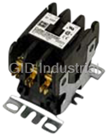
CUTLER-HAMMER C25DND330
Description
Cutler-Hammer C25DND330 Definite Purpose Contactor. Mechanical Interlock | 3-Pole | 30 Amp | Pressure Plate Terminals | 120V AC
Part Number
C25DND330
Price
Request Quote
Manufacturer
CUTLER-HAMMER
Lead Time
Request Quote
Category
Contactors
Specifications
Coil Voltage Vac Nom
120V
Contact Current Ac Max
30A
Contact Current Max
30A
Contact Voltage Ac Nom
600V
Height
152mm
Lead Free Status/RoHS Status
Lead free/RoHS Compliant
Load Current Inductive
30A
Load Current Resistive
40A
No. Of Poles
3
Nom Operating Power
7.5kW
Operating Voltage
600VAC
Relay Mounting
Panel
Rohs Compliant
Yes
Switching Current Ac1
40A
Switching Current Ac3
30A
Switching Power Ac1
3.7kW
Switching Power Ac3
7.5kW
Datasheet

Extracted Text
PG03502001E_Cover.qxd:CoverVersion6.qxd 5/15/07 1:09 PM Page 1 Definite Purpose Control Product Focus PG03502001E_InsideF&BCovers.qxd:InsideCoversPage2.qxd 5/15/07 1:34 PM Page 1 PG03502001E_Page3_1stB&W.qxd:PG03502001E_infrntCVR.qxd 5/15/07 1:39 PM Page 1 Innovation in Definite Purpose Control Eaton’s Cutler-Hammer� Definite Purpose (DP) 1 Contactors are designed to improve control of refrigeration, air conditioning, ventilation and resistance heating applications. The complete line offers everything from compact DPs to the smallest 50 ampere DP Contactor in the world — an average of 20% smaller than the competition. Always looking for new ways to improve the customer experience, Eaton launched the 50mm DP Contactor with an innovative sealed housing design to keep out contaminants and lower noise. Building on that success, the new series of Compact DPs are now available in a sleek new sealed design. Continuing to innovate and upgrade products, Eaton offers the perfect definite purpose solution for your HVACR applications. New Series of Compact Definite Purpose Contactors The new 20 – 40 ampere, single- and double-pole, Type C25 compact DP contactors feature a compact, efficient design with a low VA coil and straight- through wiring. These devices are economically priced, UL� recognized/CSA� certified, are current rated and hp/kW rated with magnet coils rated Class F, 155°C (most are Class B, 130°C) and designed with low VA current ratings for less energy consumption. With the ability to be mounted vertically, horizontally or tabletop, the new series of compact DPs will meet all your definite purpose application needs. 3 2 1. Compact DP Contactor 2. 50mm DP Contactor with Quick Connect Terminals 3. 50mm Reversing DP Contactor with Quick Connect Terminals EATON CORPORATION Innovation in Definite Purpose Control i DeŢnite Purpose Control May 2007 Description Page Product Family Overview Application Description. . . . . . . . . . . . . . . . . . . . . . . . . . . . . . . . . . . . . . . . . 1 Catalog Number Selection . . . . . . . . . . . . . . . . . . . . . . . . . . . . . . . . . . . . . . 1 Contactors 20 – 40A, Compact 1- and 2-Pole — C25 . . . . . . . . . . . . . . . . . . . . . . . . . . . 2 15 – 360A, 2-, 3- and 4-Pole — C25. . . . . . . . . . . . . . . . . . . . . . . . . . . . . . . . 4 15 – 360A, Options and Accessories . . . . . . . . . . . . . . . . . . . . . . . . . . . . . . 6 15 – 40A, 3-Pole Fuse Block . . . . . . . . . . . . . . . . . . . . . . . . . . . . . . . . . . . . . 8 15 – 75A, Reversing and 2-Speed — C65. . . . . . . . . . . . . . . . . . . . . . . . . . . 9 Starters 25 – 60A, Single and Three-Phase — A25, B25 . . . . . . . . . . . . . . . . . . . . . . 10 Overload Relay and Accessories . . . . . . . . . . . . . . . . . . . . . . . . . . . . . . . . . 12 Heater Packs — Class 10 and Class 20. . . . . . . . . . . . . . . . . . . . . . . . . . . . . 13 15 – 45A, Single and Three-Phase — A27, B27 . . . . . . . . . . . . . . . . . . . . . . 14 Overload Relay SpeciŢcations . . . . . . . . . . . . . . . . . . . . . . . . . . . . . . . . . . . 17 15 – 75A, Single and Three-Phase — A29, B29 . . . . . . . . . . . . . . . . . . . . . 19 NEMA Type 1 Enclosed Control 15 – 60A Contactors — C25. . . . . . . . . . . . . . . . . . . . . . . . . . . . . . . . . . . . . . 25 25 – 60A Starters — A25, B25 . . . . . . . . . . . . . . . . . . . . . . . . . . . . . . . . . . . . 26 15 – 45A Starters — A27, B27 . . . . . . . . . . . . . . . . . . . . . . . . . . . . . . . . . . . . 27 Dimensions . . . . . . . . . . . . . . . . . . . . . . . . . . . . . . . . . . . . . . . . . . . . . . . . . . . . . 28 Renewal Parts. . . . . . . . . . . . . . . . . . . . . . . . . . . . . . . . . . . . . . . . . . . . . . . . . . . 31 Technical Data and SpeciŢcations . . . . . . . . . . . . . . . . . . . . . . . . . . . . . . . . . . 34 Dimensions, Weights and Ratings Dimensions, weights and ratings given in this Product Guide are approximate and should not be used for construction purposes. Drawings giving exact dimensions are available upon request. All listed product speciŢcations and ratings are subject to change without notice. Photographs are representative of production units. Terms and Conditions All orders accepted by Eaton are subject to the general terms and conditions as set forth in Sellers Policy 25-000. ® Other Cutler-Hammer Products Eaton’s electrical business is a leader in the development and manufacturing of power distribution equipment, electrical control products and advanced industrial automation solutions. For more information on Cutler-Hammer products and services, visit our Web site at www.eaton.com. WARNING The installation and use of Cutler-Hammer products should be in accordance with the provisions of the U.S. National Electrical Code and/or other local codes or industry standards that are pertinent to the particular end use. Installation or use not in accordance with these codes and standards could be hazardous to personnel and/or equipment. For more information visit: www.eaton.com PG03502001E DeŢnite Purpose Control 1 Product Family Overview May 2007 Application Description ® These Cutler-Hammer ampere and horsepower rated testing procedures. The life expectancy, both electrical and devices from Eaton’s electrical business are designed for mechanical, will meet or exceed industry performance service in applications such as Refrigeration, Air Conditioning requirements for DeŢnite Purpose devices. and Resistance Heating and are manufactured to traditional If more detailed technical information is required — speciŢ- Cutler-Hammer standards for quality and reliability. They are cations, ratings, etc. — contact your local Eaton distributor subjected to stringent quality assurance inspections and or sales ofŢce. Catalog Number Selection Table 1. DeŢnite Purpose Control Catalog Numbering System C 2 5 D N A 2 1 5 A A 1 6 1 - 8 4 Model Bulk Packaging C = Contactor Blank = individual pkg. A = Three-Phase Starter -84 = 20 pc./pkg. (C25D_) B = Single-Phase Starter 50 pc./pkg. (C25A_, C25B_, C25C_) -86 = Rotate coil terminals 180° Type for 15A – 50A Contactors 25 = Non-reversing Contactors & Starters 27 = Non-reversing Starters Fuse Blocks 29 = Non-reversing Starters 65 = Reversing Contactors 161 = Class M, 600V, 30A 237 = Class G, 300V, 15A 238 = Class G, 300V, 20A Contactor Frame Size 231 = Class G, 300V, 30A 232 = Class G, 300V, 60A A = Compact 1-Pole 361 = Class J, 600V, 30A B = Compact 2-Pole 362 = Class J, 600V, 60A C = Compact 1-Pole W/Shunt 431 = Class T, 300V, 30A D = 15 – 50A, 2- and 3-Pole 432 = Class T, 300V, 60A E = 25 – 40A, 4-Pole 461 = Class T, 600V, 30A F = 60 – 75A, 2- and 3-Pole 462 = Class T, 600V, 60A G = 90A, 2- and 3-Pole 521 = Class H, 250V, 30A H = 120A, 2- and 3-Pole 522 = Class H, 250V, 60A K = 200 and 300A, 3-Pole 621 = Class R, 250V, 30A L = 360A, 3-Pole 622 = Class R, 250V, 60A For Starters Only C = Common Control Wiring Auxiliary Contacts (Side Mount) S = Separate Control Wiring A = 1NO Pressure Plate B = 1NC Pressure Plate Enclosure Type C = 1NO-1NC Pressure Plate D = 2NO Pressure Plate N = Open with Metal Mounting Plate E = 2NC Pressure Plate R = Open with DIN Rail Mounting Adapter F = 1NO Pressure Plate and QC (2- and 3-Pole, 15 – 50A Contactors Only) G = 1NC Pressure Plate and QC G = NEMA Type 1 Enclosed H = 1NO-1NC Pressure Plate and QC J = 2NO Pressure Plate and QC K = 2NC Pressure Plate and QC Power Terminals L = 1NO-1NC Snap Switch QC Only A = Binding Head Screw M =2NO-2NC Snap Switch QC Only B = Binding Head Screw and Quick Connect Terminals (side by side) � Coil Selection C = Screw/Pressure Plate D = Screw/Pressure Plate and Quick Connect A = 110 – 120V AC, 50/60 Hz R = 12V AC, 50/60 Hz � Terminals (side by side) B = 208 – 240V AC, 50/60 Hz T = 24V AC, 50/60 Hz E = Box Lugs (Posidrive Setscrew) C = 440 – 480V AC, 50/60 Hz 1R = 12V DC F = Box Lugs (Posidrive Setscrew) and Quick D = 550 – 600V AC, 50/50 Hz 1T = 24V DC Connect Terminals (side by side) H = 277V AC, 60 Hz 1W = 48V DC G = Binding Head Screw and Quick Connect J = 220 – 240 V AC, 50/60 Hz 1A = 120V DC Terminals (vertical in-line) L = 380 – 415V AC, 50 Hz H = Screw/Pressure Plate and Quick Connect � Terminals (vertical in-line) J = Box Lugs (Posidrive Setscrew) and Quick Current Rating Connect Terminals (vertical in-line) 15 = 15A 75 = 75A K = Box Lugs (Hex Socket Allen Head Setscrew) No. of Poles 25 = 25A 90 = 90A L = Box Lugs (Hex Socket Allen Head Setscrew) and 1 = 1-Pole 30 = 30A 120 = 120A Quick Connect Terminals (side by side) 2 = 2-Pole 40 = 40A 200 = 200A M =Box Lugs (Hex Socket Allen Head Setscrew) and 3 = 3-Pole 50 = 50A 300 = 300A Quick Connect Terminals (vertical in-line) 4 = 4-Pole 60 = 60A 360 = 360A � Not available on 50A devices. PG03502001E For more information visit: www.eaton.com DeŢnite Purpose Control 2 Contactors May 2007 20 – 40A, Compact 1- and 2-Pole — C25 Contents Standards and CertiŢcations Description Page ■ UL Recognized Components: UL File ■ ARI 780/790 Standard Number E1491, Guides NLDX2 and Compact 1- and 2-Pole ■ RoHS Compliance NLDX8 Contactors 20 – 40A ■ CSA CertiŢed Components: CSA Product Description. . . . . . . 2 C22.2 No. 14-05, File Number Standards and 238083 Class 3211 84 CertiŢcations . . . . . . . . . . . 2 ■ IEC 60947-4-1 Technical Data — ■ EN 60947-4-1 SpeciŢcations . . . . . . . . . . 2 Options . . . . . . . . . . . . . . . . . 2 Dimensions . . . . . . . . . . . . . 3 Product Selection . . . . . . . . 3 Technical Data — SpeciŢcations ■ Insulation Voltage: 690V Table 2. Coil Characteristics ■ Current Rated and hp/kW Rated AC Coil Max. Max. Max. Voltage Inrush Sealed Sealed ■ Contacts: Double Break 50/60 Hz VA VA Watts ■ Magnet Coil: Class F, 155°C One-Pole ■ Contact Arc Covers are standard on 24 33 6 2 all Contactors 120 33 6 2 208/240 33 6 2 ■ Standard Power Terminals — 277 33 6 2 ❑ 5/16" Hex Washer Head Screws Two-Pole ❑ Quad (4) Quick Connect Terminals 24 41 6.5 3 on all Line and Load Terminals 120 41 6.5 3 208/240 41 6.5 3 ❑ Box Lugs available as option 277 41 6.5 3 480 41 6.5 3 ■ Contactors are marked with Line Compact 2-Pole and Load Terminal Designations ■ Operating Temperature Range: Options Product Description -13 to 158°F (-25 to 70°C) Table 3. Compact Options — ® Cutler-Hammer 20 – 40A, single- and ■ Terminal Wire Range — Factory Installed double-pole, Type C25 contactors from ❑ Hex Washer Head Screws: Description Eaton’s electrical business feature a * 16 – 10 AWG, 30 lb-in torque compact, efŢcient design with a low Box lugs with quick connects for rating VA coil and straight-through wiring. 20 – 40A contactors: ❑ Box Lugs: 16 – 10 AWG, 35 lb-in 1-Pole New contactor housing design effec- 1-Pole with shunt torque rating; 8 AWG, 40 lb-in tively limits dust and other contami- 2-Pole torque rating; 6 – 4 AWG, 45 lb-in nants from magnet structure — To order replace letter in the 6th posi- torque rating reduces or eliminates noise. These tion of Catalog Number with letter F. economically priced, UL recognized/ EXAMPLE: C25BNF240A ■ Mounting Position: Vertical, CSA certiŢed, ampere rated devices Horizontal or Tabletop are well suited for use in heating/air conditioning, refrigeration, data pro- cessing and food service applications. Discount Symbol . . . . . . . . . . . . . . . . . . . . . . 1CD-5C * Consult Sales OfŢce for Pricing For more information visit: www.eaton.com PG03502001E DeŢnite Purpose Control 3 Contactors May 2007 20 – 40A, Compact 1- and 2-Pole — C25 Product Selection When Ordering Specify Table 4. Catalog Numbering System ■ Catalog Number plus Magnet Coil C25BNB230 A SufŢx. ■ Modify Catalog Number for any Incomplete Magnet options required — see factory Catalog Number Coil Suffix installed Options Page 2. Table 5. Compact Contactors Product Selection— Open Type � Ampere Ratings Max. Motor Max. Motor Catalog * �� Horsepower Kilowatts Number Compact 1-Pole Inductive Resistive Locked Rotor Full Load 240 – 277V 480V 600V 115V 230V 115V 230V Single-Pole 25 30 150 50 40 2 3 1.5 2.2 C25ANB125_ 30 40 150 75 50 2 5 1.5 3.7 C25ANB130_ 40 50 240 200 160 3 7-1/2 2.2 5.5 C25ANB140_ Single-Pole with Shunt 25 30 150 50 40 2 3 1.5 2.2 C25CNB125_ 30 40 150 75 50 2 5 1.5 3.7 C25CNB130_ 40 50 240 200 160 3 7-1/2 2.2 5.5 C25CNB140_ Double-Pole 20 30 120 100 80 1-1/2 3 1.1 2.2 C25BNB220_ 25 35 150 125 100 2 3 1.5 2.2 C25BNB225_ 30 40 150 125 100 2 5 1.5 3.7 C25BNB230_ Compact 1-Pole with Shunt 40 50 240 200 160 3 7-1/2 2.2 5.5 C25BNB240_ � Rating per pole. � Incomplete Catalog Number. Replace underscore (_) in Catalog Number with Coil SufŢx letter from Table 6. � Bulk pack quantities are available in quantities of 50, contact local sales ofŢce. Table 6. Magnet Coil Selection AC Coil Voltage Coil 50/60 Hz SufŢx 24 T 110 – 120 A 208 – 240 B 277 H 380 – 415 (50 Hz); 440 – 480 (60 Hz) C Compact 2-Pole Dimensions 0.03 0.21 0.03 0.21 0.25 (6.3) 0.25 (6.3) (0.8) (5.2) (0.8) (5.2) 1.50 1.77 2.40 3.19 1.50 1.77 2.40 3.19 (38) (45) (61) (81) (38) (45) (61) (81) 1.61 (41) 1.61 (41) 2.32 (59) 2.32 (59) 1.97 (50) 1.97 (50) 1-Pole and 1-Pole +Shunt 2-Pole Ship. Wt.: 0.5 lb. (0.2 kg) Ship. Wt.: 0.7 lb. (0.3 kg) Technical Data. . . . . . . . . . . . . . . . . . . . . . . . Page 2 Figure 1. Compact Approximate Dimensions in Inches (mm) and Shipping Weights Options . . . . . . . . . . . . . . . . . . . . . . . . . . . . . . Page 2 Discount Symbol . . . . . . . . . . . . . . . . . . . . . . 1CD-5C * Consult Sales OfŢce for Pricing PG03502001E For more information visit: www.eaton.com DeŢnite Purpose Control 4 Contactors May 2007 15 – 360A, 2-, 3- and 4-Pole — C25 ■ Contacts: Double break ❑ Box lugs — 60 – 75A ■ Coil terminals: 10 – 14 AWG – Upper Level: 14 – 2 AWG ■ Ambient temperature: 150°F (65°C) – Lower Level: 14 – 6 AWG maximum Note: The box lugs on the 15 – 75A ■ UL recognized, CSA certiŢed and device can accept two conductors per conform to ARI 780 pole. ■ CE mark ❑ Box lugs — 90A: 1/0 – 14 AWG ■ Terminal wire range: ❑ Box lugs — 120A: 3/0 – 8 AWG ❑ #8–32 binding head screw: ❑ Box lugs — 200 – 300A: 350 14 – 12 AWG (one conductor- MCM – 6 AWG solid) 50 mm DP Contactor ❑ #8–32 screw/pressure plate: ❑ Box lugs — 360A: 750 MCM – 2 AWG – 14 – 8 AWG (one conductor) Product Description Table 7. Lighting Duty Ratings – 14 – 8 AWG (two conductors) ® (25A to 50A Only) Cutler-Hammer Type C25 DeŢnite ❑ Box lugs — 15 – 50A: Purpose Contactors 15A through 360A, C25D_ Tungsten – # 2 posidrive screw or 5/32 hex Inductive Rating & Ballast (480V) from Eaton’s electrical business incor- socket screw porate most competitive contactor – Upper Level: 14 – 4 AWG (one 25A 30A mounting dimensions into a single conductor) 30A 40A baseplate. Contactors are dual-rated 40A 50A – Lower Level: 14 – 6 AWG (one with inductive and resistive ratings as 50A 60A conductor) well as horsepower and kilowatt rat- ings. C25 contactors are furnished with Table 8. IEC/CE Ratings (IEC 60947-4-1, EN 60947-4-1) for 15A through 50A C25D_Contactors pressure plates and quick connect ter- C25D_ AC-1 (Ic) AC-3 (Ie) AC-4 (Ie) AC-8a minals as standard on 15, 25 and 30A Inductive devices and with box lugs and quick- 480V 600V 480V 600V 480V 600V 480V 600V Rating connect terminals on 40, 50, 60 and 75A. Other terminal conŢgurations are 15A 20A 20A 15A 15A 15A — 15A 15A 25A 30A 30A 25A 25A 25A — 25A 25A available, see Table 14. Contactors will 30A 40A 40A 30A 30A 30A — 30A 30A accept add-on auxiliary contacts — 40A 50A — 40A — 40A — 40A — order factory assembled or as kits for 50A 65A 65A 50A 50A 50A — 50A 50A Ţeld installation. The separately available snap-on Table 9. DC Ratings (15A to 50A Only) mechanical interlock permits interlock- Voltage 2-Pole, 2-Pole, 3-Pole, 3-Pole, ing two contactors for reversing or 15 – 30A Inductive 40A Inductive 15 – 30A Inductive 40A Inductive two-speed applications. UL/ DC-3/ UL/ DC-3/ UL/ DC-3/ UL/ DC-3/ CSA DC-5 CSA DC-5 CSA DC-5 CSA DC-5 Contactors rated 15 – 50A only are available with DIN rail mount as a fac- FLA hp I FLA hp I FLA hp I FLA hp I e e e e tory installed option. 240V DC 3 Poles in Series — — — — — — 4 3/4 4 5 1 5 120V DC 3 Poles in Series — — — — — — 8 3/4 8 10 1 10 Standards and CertiŢcations 120V DC 2 Poles in Series 5.5 1/2 5.5 8 3/4 8 5.5 1/2 5.5 8 3/4 8 ■ UL Recognized Components 120V DC per Pole 2 1/10 2 3.5 1/4 3.5 2 1/10 2 3.5 1/4 3.5 UL File #E-1491, Guide NLDX2 24V DC per Pole 15 — 15 20 — 20 15 — 15 20 — 20 ■ CSA CertiŢed Components File #LR353, Class 3211 04, 481301 Table 10. Contactor Torque Ratings & 122201 Contactor Size Terminal Wire Range Tightening Torque ■ IEC 60947-4-1 � 15 – 50A 8–32 Binding Head Screw 12 – 14 AWG 22 lb-in ■ EN 60947-4-1 Screw/Pressure Plate 8 – 14 AWG 15 lb-in Box Lug 12 – 14 AWG 15 lb-in 10 AWG 25 lb-in 8 AWG 40 lb-in ■ RoHS Compliance (15A to 50A Only) 4 – 6 AWG 45 lb-in � 60 – 75A Box Lug 10 – 14 AWG 40 lb-in 8 AWG 45 lb-in 3 – 6 AWG 50 lb-in 90A Box Lug 1/0 – 14 AWG 60 lb-in Technical Data and 120A Box Lug 8 AWG 40 lb-in 4 – 6 AWG 45 lb-in SpeciŢcations 3 – 1/0 AWG 50 lb-in ■ Magnet coil: 200 – 300A Box Lug 6 – 350 MCM 200 lb-in ❑ Class B (C25E, F, G, H and K), 360A Box Lug 2 – 750 MCM 550 lb-in 130°C � The box lugs on the 15 – 50A device can accept 2 conductors per pole, the upper section will ❑ Class F (C25D and L), 155°C accept 4 – 14 AWG and the lower section will accept 6 – 14 AWG. � ❑ Class H (C25D), 180°C (Available The box lugs on the 60 – 75A device can accept 2 conductors per pole, the upper section will as factory installed option) accept 3 – 14 AWG and the lower section will accept 6 – 14 AWG. For more information visit: www.eaton.com PG03502001E DeŢnite Purpose Control 5 Contactors May 2007 15 – 360A, 2-, 3- and 4-Pole — C25 Table 11. Catalog Numbering System Product Selection When Ordering Specify ■ Modify Catalog Number for any C25DND215AX options required — see Options, ■ Catalog Number plus Magnet Coil Page 6. Incomplete Magnet Option SufŢx, below. Catalog Coil Suffix Code as ■ Catalog Numbers of accessory kits Number necessary required, Page 6. Table 12. C25 Contactors Product Selection— Open Type Rating, Amperes Maximum Motor Maximum Motor Number Open Type with Metal Open Type with DIN Horsepower Kilowatts of Poles Mounting Plate Rail Adapter Inductive Resistive Line Locked 1-Phase 3-Phase 1-Phase 3-Phase Catalog Catalog * * �� �� Full Load per Pole Voltage Rotor Number Number 15 20 115 90 3/4 — 0.40 — 2 C25DND215_ C25DRD215_ 230 90 2 3 1.5 2.2 3 C25DND315_ C25DRD315_ 460 75 — 5 — 3.7 575 60 — 5 — 3.7 25 35 115 150 2 — 1.5 — 2 C25DND225_ C25DRD225_ 230 150 3 7-1/2 2.2 5.5 3 C25DND325_ C25DRD325_ 460 125 — 10 — 7.5 4 C25END425_ 575 100 — 10 — 7.5 30 40 115 180 2 — 1.5 — 2 C25DND230_ C25DRD230_ 230 180 5 10 3.7 7.5 3 C25DND330_ C25DRD330_ 460 150 — 15 — 11 4 C25END430_ 575 120 — 15 — 11 40 50 115 240 3 — 2.2 — 2 C25DNF240_ C25DRF240_ 230 240 7-1/2 10 5.5 7.5 3 C25DNF340_ C25DRF340_ 460 200 — 20 — 15 4 C25ENF440_ 575 160 — 20 — 15 50 65 115 300 3 — 2.2 — 2 C25DNJ250_ C25DRJ250_ 230 300 10 15 7.5 11 3 C25DNJ350_ C25DRJ350_ 460 250 — 30 — 22 575 200 — 30 — 22 60 75 115 360 5 — 3.7 — 2 C25FNF260_ NA 230 360 10 20 7.5 15 3 C25FNF360_ 460 300 — 40 — 30 575 240 — 40 — 30 75 90 115 450 5 — 3.7 — 2 C25FNF275_ NA 230 450 15 20 11 18.5 3 C25FNF375_ 460 375 — 50 — 37 575 300 — 50 — 37 90 120 115 540 7-1/2 — 5.7 — 2 C25GNF290_ NA 230 540 20 30 15.1 22 3 C25GNF390_ 460 450 — 50 — 37 575 360 — 50 — 37 120 140 230 720 — — — — 3 C25HNE3120_ NA 460 720 — — — — 575 570 — — — — 200 200 240 1200 — — — — 3 C25KNE3200_ NA 480 1200 — — — — 600 1000 — — — — 300 300 240 1800 — — — — 3 C25KNE3300_ NA 480 1800 — — — — 600 1500 — — — — 360 360 240 2320 — — — — 3 C25LNE3360_ NA 480 2320 — — — — 600 1900 — — — — � � Incomplete Catalog Number. Replace under- 104 – 120V 50/60 Hz for 60A, 75A and all Table 13. Magnet Coil Selection score (_) in Catalog Number with Magnet 4-Pole Contactors (25A – 40A). Voltage Coil � Coil SufŢx from table below. Class H AC Coils available as option for SufŢx 60 Hertz 50 Hertz � Carton quantities including 20 individually 15A – 50A Contactor. Add 2 before AC Coil � AC packaged units are available for 2- and 3- SufŢx letter. � pole units through 60A inductive. 12 12 R � � Contactors with DC coils (only available up 24 24 T � � to 75A) include an early break NC auxiliary 110 – 120 110 – 120 A � contact, C320KGD1. See Page 33 for more 208 — E � details. 208 – 240 208 – 240 B � � Available only for 15A through 75A contactors 240 220 J and 4-pole contactors. 277 — H � Available through 75A. — 380 – 415 L � Available through 120A. 440 – 480 440 – 480 C Technical Data. . . . . . . . . . . . . . . . . . . . Pages 4, 34 � Available 120 – 360A. 550 – 600 550 – 600 D � Options . . . . . . . . . . . . . . . . . . . . . . . . . . Page 6 Available 15 – 90A, others 240V. � DC � Accessories . . . . . . . . . . . . . . . . . . . . . . Page 6 Available through 50A. 12 1R Dimensions. . . . . . . . . . . . . . . . . . . . . . . Page 30 24 1T Discount Symbol . . . . . . . . . . . . . . . . . . 1CD-5C 48 1W � 120 1A * Consult Sales OfŢce for Pricing PG03502001E For more information visit: www.eaton.com DeŢnite Purpose Control 6 Contactors May 2007 15 – 360A, Options and Accessories Options — Factory Installed Accessories To order C25, C65, A25 and B25 Contactors and Starters with Auxiliary Contact Kits (Side Mounted) the factory installed options listed below, change the basic Catalog Number listed in the Product Selection Table as noted. Table 14. Factory Installed Options Description Code Number of * Letter Poles Terminals — 15A through 50A Binding Head Screws Without Quick Connect Terminals A 2-, 3-, 4-Pole With Quick Connect Terminals B 2-, 3-, 4-Pole (Side-by-Side) With Quick Connect Terminals G 2-, 3-Pole Side Mounted Auxiliary Contact (Vertical In-Line) � Screw/Pressure Plate Table 16. Heavy-Duty Pilot Rated for 10A at 600V AC Without Quick Connect Terminals C 2-, 3-, 4-Pole Circuit With Standard Pressure With Pressure Plate and With Quick Connect Terminals D 2-, 3-, 4-Pole Plate Terminals Quick Connect Terminals (Side-by-Side) With Quick Connect Terminals H 2-, 3-Pole Catalog Catalog * * (Vertical In-Line) Number Number Box Lugs For 15 through 75A (#2 Posidrive/Slotted Screw) � 1NO C320KG1 C320KG11 Without Quick Connect Terminals E 2-, 3-, 4-Pole � 1NC C320KG2 C320KG12 With Quick Connect Terminals F 2-, 3-, 4-Pole 1NO-1NC C320KG3 C320KG13 (Side-by-Side) 2NO C320KG4 C320KG14 With Quick Connect Terminals J 2-, 3-Pole 2NC C320KG5 C320KG15 (Vertical In-Line) Box Lugs For 90A (Hex Socket Allen Head Screw) 1NO — C320DPG10 Without Quick Connect Terminals K 2-, 3-Pole 1NC — C320DPG01 With Quick Connect Terminals L 2-, 3-Pole 1NO-1NC — C320DPG11 (Side-by-Side) 2NO — C320DPG20 With Quick Connect Terminals M 2-, 3-Pole For 120 through 360A (Vertical In-Line) Terminals — 60A through 75A 1NO C320KGS20 — 1NC C320KGS21 — Replace letter in the 6th position of Catalog Number with Code Letter listed 1NO-1NC C320KGS22 — below. EXAMPLE: Change C25FNF250 to C25FNE250. Box Lugs (Slotted Screw) Without Quick Connect Terminals E 2-, 3-Pole With Quick Connect Terminals F 2-, 3-Pole � 4-Pole contactors have box lugs with slotted screws. � Screw/Pressure Plate terminals are not available on 50A Contactors. Auxiliary Contacts (Side Mount) Table 15. Auxiliary Contacts — Factory Installed Add Code Letter listed below to complete Catalog Number. EXAMPLE: Change C25DND215A to C25DND215AA. Side Mounted Snap Switch Description With Standard With Quick Snap Switch Table 17. Snap Switch Design Side Mounted Auxiliary Contacts Pressure Plate Connect Terminals Design with Quick Terminals Connect Terminals Circuit Snap Switch Design with Quick Connect Terminals Code Code Code * * * Catalog * Letter Letter Letter Number � For 15 through 90A 1NO-1NC C320SNP11 1NO A F — 2NO-2NC C320SNP22 1NC B G — 1NO-1NC C H — 2NO D J — 2NC E K — For 15 through 75A 1NO-1NC — — L 2NO-2NC — — M For 120 through 360A 1NO A — — 1NO-1NC C — — 2NO D — — 2NC E — — Special Marking Special contactor marking, consult local sales ofŢce. � 90A available only with binding head screw and quick connect terminals. Discount Symbol . . . . . . . . . . . . . . . . . . . . . 1CD-5C * Consult Sales OfŢce for Pricing For more information visit: www.eaton.com PG03502001E DeŢnite Purpose Control 7 Contactors May 2007 15 – 360A, Options and Accessories Magnet Coil Quick Connect Terminal Solid-State ON DELAY Timer Table 18. Magnet Coil Quick Connect Terminal Description * Extra Dual Quick Connect Terminals (U-shaped) for � Magnet Coil Terminals � Solid-State To order, add SufŢx Number 9 to the complete Catalog Number. Example: C25DND215A9. ON DELAY Timer Auxiliary Contact Kits (Top Mounted) Side Mounted on C25D, C25E and C25F Frame This timer is designed to be wired in series with the load (typically a coil). When the START button is pushed (power applied to timer), the ON DELAY timing function starts. At the completion of the set timing period, timer and series Top Mounted wired load will both be energized. Auxiliary Contact Table 21. Solid-State ON DELAY Timer Table 19. Heavy-Duty Pilot Rated for 10A at 600V AC Timing Catalog * ��� Circuit With Standard Pressure Plate Terminals Range Number Catalog * .1 – 1.0 Seconds C320TDN1_ Number 1 – 30 Seconds C320TDN30_ � For 15 through 75A 30 – 300 Seconds C320TDN300_ 5 – 30 Minutes C320TDN3000_ 1NO C320KGT1 � 1NC C320KGT2 Add operating voltage SufŢx to Catalog Number. A = 120V, B = 240V, E = 208V 1NO-1NC C320KGT3 � Rated .5 ampere pilot duty — not to be used on larger contactors. 2NO C320KGT4 � 2NC Terminal connections are quick connects only. Two per side. C320KGT5 3NO C320KGT9 Separate Enclosures 2NO-1NC C320KGT10 1NO-2NC C320KGT11 3NC C320KGT12 4NO C320KGT13 3NO-1NC C320KGT14 2NO-2NC C320KGT15 1NO-3NC C320KGT16 NEMA 1 Enclosure — 4NC C320KGT17 Cat. No. C799B19 � Not available for 4-pole contactors (15 – 40 Amp). Mechanical Interlock Kit Table 22. Separate Enclosures — NEMA 1 Application Catalog * Number 15 through 50A, 2- and 3-Pole C799B18 60A, 2- and 3-Pole or C799B19 Mechanical 25 through 40A, 4-Pole Interlock Table 20. Mechanical Interlock Kit for 15 through 75A Catalog * Number C321KM60B Discount Symbol . . . . . . . . . . . . . . . . . . . . . . 1CD-5C * Consult Sales OfŢce for Pricing PG03502001E For more information visit: www.eaton.com DeŢnite Purpose Control 8 Contactors May 2007 15 – 40A, 3-Pole Fuse Block Optional 3-Pole Fuse Block Available only on 3-Pole, 15 – 50A To order factory assembled, add Contactors SufŢx Number from table below to Catalog Number of contactor listed on Designed to save space and reduce Page 5 and make necessary price addi- installation costs, these 3-pole Fuse tion. EXAMPLE: C25DND325A361. Blocks will accommodate a variety of fuse classes and fuse holders to satisfy a wide range of electrical/electronic applications such as commercial space and water heaters, dishwashers, food coolers and sterilizing equipment. They are supplied either factory assembled, mounted and wired to the 3-Pole Fuse Block contactor or in kit form. Table 23. 3-Pole Fuse Block Fuse Holder Fuse Dimensions Terminal Type and Factory Installed Field Installation Kit * in Inches (mm) Maximum Wire Size Ordering SufŢx Catalog Number Volts Amperes Diameter Length Class M 600 30 0.41 (10.4) 1.50 (38.1) Pressure Plate 10 AWG Cu 161 C350KM61 Class G 600 15 0.41 (10.4) 1.31 (33.3) Pressure Plate 10 AWG Cu 237 C350KG37 20 1.41 (35.8) Pressure Plate 10 AWG Cu 238 C350KG38 480 30 0.41 (10.4) 1.63 (41.4) Pressure Plate 10 AWG Cu 231 C350KG31 60 2.25 (57.2) Box Lug 2 AWG Cu/Al 232 C350KG32 Class J 600 30 0.81 (20.6) 2.25 (57.2) Pressure Plate 10 AWG Cu 361 C350KJ61 60 1.06 (26.9) 2.38 (60.5) Box Lug 2 AWG Cu/Al 362 C350KJ62 Class T 300 30 0.41 (10.4) 0.88 (22.4) Box Lug 6 AWG Cu 431 C350KT31 60 0.56 (14.2) 0.88 (22.4) Box Lug 2 AWG Cu/Al 432 C350KT32 600 30 0.56 (14.2) 1.50 (38.1) Box Lug 6 AWG Cu 461 C350KT61 60 0.81 (20.6) 1.56 (39.6) Box Lug 2 AWG Cu/Al 462 C350KT62 Class H 250 30 0.56 (14.2) 2.00 (50.8) Pressure Plate 10 AWG Cu 521 C350KH21 60 0.81 (20.6) 3.00 (76.2) Box Lug 2 AWG Cu/Al 522 C350KH22 Class R 250 30 0.56 (14.2) 2.00 (50.8) Pressure Plate 10 AWG Cu 621 C350KR21 60 0.81 (20.6) 3.00 (76.2) Box Lug 2 AWG Cu/Al 622 C350KR22 Dimensions Table 24. Approximate Dimensions for 3-Pole Fuse Block and Contactor Fuse Size Dimensions in Inches (mm) Class Amps Volts Wide High Deep A B C For Dimensions Not Shown, See Next Page. G15 600 2.41 (61) 2.81 (71) 5.14 (131) 20 2.41 (61) 2.81 (71) 5.14 (131) 30 480 2.41 (61) 2.81 (71) 5.14 (131) 60 2.62 (67) 4.25 (108) 5.18 (132) H30 250 3.00 (76) 3.03 (77) 5.33 (135) A 60 4.22 (107) 4.75 (121) 5.86 (149) Front View J30 600 4.81 (122) 4.12 (105) 5.92 (150) 60 4.81 (122) 4.12 (105) 5.92 (150) M 30 600 2.41 (61) 2.81 (71) 5.14 (131) B R30 250 3.00 (76) 3.03 (77) 5.33 (135) 60 4.22 (107) 4.75 (121) 5.86 (149) T30 300 3.44 (87) 2.75 (70) 5.43 (138) 60 300 3.44 (87) 2.75 (70) 5.43 (138) C 30 600 3.75 (95) 3.19 (81) 5.36 (136) Side View 60 600 4.87 (124) 2.94 (75) 5.68 (144) Discount Symbol . . . . . . . . . . . . . . . . . . . . . . 1CD-5C Figure 2. 3-Pole Fuse Block and Contactor Dimensions * Consult Sales OfŢce for Pricing For more information visit: www.eaton.com PG03502001E DeŢnite Purpose Control 9 Contactors May 2007 15 – 75A, Reversing and 2-Speed — C65 Table 25. Catalog Numbering System Product Description Standards and CertiŢcations C65DND315AX ® Cutler-Hammer C65 Reversing ■ UL Recognized Components Contactors from Eaton’s electrical UL File #E-1491, Guide NLDX2 business are furnished with pressure Incomplete Magnet Option ■ CSA CertiŢed Components Catalog Coil Suffix Code as plates and quick connect terminals as File #LR353, Guide 380w-1.14 Class Number necessary standard on 15, 25 and 30A devices 3211 04 and with box lugs and quick connect terminals on 40, 50, 60 and 75A. Other terminal conŢgurations are available — see Factory Installed Options Table on Page 6. Reversing contactors will accept add-on Auxiliary Contacts on either side — order factory assembled or as kits for Ţeld installation. See Page 6. C65 Reversing Contactor Product Selection Table 26. Reversing and 2-Speed Contactors Product Selection — Open Type — Unwired, Mechanically Interlocked Only Rating, Amperes Maximum Motor Maximum Motor Number Open Type with Metal Open Type with DIN Horsepower Kilowatts of Poles Mounting Plate Rail Adapter Inductive Resistive Line Locked 1-Phase 3-Phase 1-Phase 3-Phase Catalog Catalog * * � � Full Load per Pole Voltage Rotor Number Number 15 20 115 90 3/4 — 0.40 — 2 C65DND215_ C65DRD215_ 230 90 2 3 1.5 2.2 3 C65DND315_ C65DRD315_ 460 75 — 5 — 3.7 575 60 — 5 — 3.7 25 35 115 150 2 — 1.5 — 2 C65DND225_ C65DRD225_ 230 150 3 7-1/2 2.2 5.5 3 C65DND325_ C65DRD325_ 460 125 — 10 — 7.5 575 100 — 10 — 7.5 30 40 115 180 2 — 1.5 — 2 C65DND230_ C65DRD230_ 230 180 5 10 3.7 7.5 3 C65DND330_ C65DRD330_ 460 150 — 15 — 11 575 120 — 15 — 11 40 50 115 240 3 — 2.2 — 2 C65DNF240_ C65DRF240_ 230 240 7-1/2 10 5.5 7.5 3 C65DNF340_ C65DRF340_ 460 200 — 20 — 15 575 160 — 20 — 15 50 65 115 300 3 — 2.2 — 2 C65DNJ250_ C65DRJ250_ 230 300 10 15 7.5 11 3 C65DNJ350_ C65DRJ350_ 460 250 — 30 — 22 575 200 — 30 — 22 60 75 115 360 5 — 3.7 — 2 C65FNF260_ NA 230 360 10 20 7.5 15 3 C65FNF360_ 460 300 — 40 — 30 575 240 — 40 — 30 75 90 115 450 5 — 3.7 — 2 C65FNF275_ NA 230 450 15 20 11 18.5 3 C65FNF375_ 460 375 — 50 — 37 575 300 — 50 — 37 � Incomplete Catalog Number. Replace Table 27. Magnet Coil Selection Table 28. Magnet Coil Options underscore (_) with Magnet Coil SufŢx � Volts Coil SufŢx Description from Table 27. * � 60 Hz 50 Hz Available through 50A. Extra dual quick connect terminals � 104 – 120V 50/60 Hz for 60A, 75A. (“U” shaped) for magnet coil 12 12 R � Class H AC Coils available as option for terminals. 24 24 T To order, add SufŢx Number 9 to 15A – 50A Contactor. Add 2 before AC Coil � � 110 – 120 110 – 120 A the complete Catalog Number. SufŢx letter. 208 – 240 208 – 240 B EXAMPLE: C65DND315A9. � 240 220 J 277 — H — 380 – 415 L 440 – 480 440 – 480 C Torque Ratings. . . . . . . . . . . . . . . . . . . . . . . . Page 4 550 – 600 550 – 600 D Options . . . . . . . . . . . . . . . . . . . . . . . . . . . . . . Page 6 Dimensions. . . . . . . . . . . . . . . . . . . . . . . . . . . Page 30 Discount Symbol . . . . . . . . . . . . . . . . . . . . . . 1CD-5C * Consult Sales OfŢce for Pricing PG03502001E For more information visit: www.eaton.com DeŢnite Purpose Control 10 Starters May 2007 25 – 60A, Single and Three-Phase — A25, B25 Table 31. Overload Relay UL/CSA Contact Contents Features Ratings Control Circuit Description Page Overload Relay AC Volts 120V 240V 480V 600V Starters 25 – 60A NC Contact B600 ■ Selectable Manual or Automatic Reset operation Product Description. . 10 Make and 30A 15A 7.5A 6A Break ■ Interchangeable Heater Packs Features . . . . . . . . . . . 10 Break 3A 1.5A 0.75A 0.6A adjustable ±24% to match motor Standards and FLA and calibrated for use with 1.0 Continuous 5A 5A 5A 5A CertiŢcations . . . . . . 10 and 1.15 service factor motors NO Contact C600 Technical Data ■ Class 10 or 20 heater packs Make and 15A 7.5A 3.375A 3A and SpeciŢcations. . . 10, 34 Break ■ Bimetallic, ambient compensated Product Selection . . . 11 operated. Trip free mechanism. Break 1.5A 0.75A 0.375A 0.3A Overload Relay . . . . . 12 ■ Electrically isolated NO-NC contacts Continuous 2.5A 2.5A 2.5A 2.5A (pull RESET button to test) Accessories . . . . . . . . 12 ■ Overload trip indication Heater Packs. . . . . . . . 13 Wire “C” ■ Shrouded or Ţngerproof terminals (Supplied Dimensions . . . . . . . . 28 with to reduce possibility of electrical Common Renewal Parts . . . . . . 31 shock Control) ■ Single-phase sensitivity L1 L2 1NO Aux. Product Description Contact Standards and CertiŢcations 1 (When 13 Supplied) ® Cutler-Hammer A25 and B25 DeŢnite ■ UL Recognized Components 14 Purpose Starters from Eaton’s electrical UL File #E-1491, Guide NLDX2 business combine the features and Wire “D” 98 ■ CSA CertiŢed Components (Supplied ţexibility of the C25 DeŢnite Purpose with File #LR353, Guide 380W-1.14 97 Contactors and Freedom Series Bi- 1NO Aux. Class 3211 04 96 Contact) metallic Ambient Compensated Over- load Relays mounted on a common 95 Reset 2/T1 4/T2 mounting plate. T1 T2 Technical Data and AC Motor SpeciŢcations Single-Phase Table 29. Terminal Wire Sizes Connections � Line Side (Contactor) Terminal Wire Range — Solid or Wire “C” (Supplied Type Stranded with Power Coil Terminals Common Terminals Control) Screw/ 8 – 14 AWG 12 – 16 AWG Pressure Plate L1 L2 L3 1NO Aux. Contact Box Lug — 4 – 14 AWG 12 – 16 AWG 1 (When 25 – 50A 13 Supplied) Box Lug — 3 – 14 AWG 12 – 16 AWG 14 60A Wire “D” 98 � Line side (contactor) torque ratings can be (Supplied with found on Page 4. A25 Starter 97 1NO Aux. 96 Contact) Table 30. Power Terminals — Load — Cu Only (Stranded or Solid) 95 2/T1 4/T2 6/T3 Terminal Range Torque Rating T1 T2 T3 25 and 30 14 – 6 AWG 20 lb-in (14 – 10 Ampere AWG) 40, 50 14 – 2 AWG 35 lb-in (14 – 10 and 60 AWG) AC Motor Ampere 40 lb-in (8 AWG) Three-Phase 45 lb-in (6 – 4 AWG) Connections 50 lb-in (3 – 2 AWG) Control Terminals — Cu Only Figure 3. Starter Wiring Diagrams 12 – 16 AWG stranded, 12 – 14 AWG solid For more information visit: www.eaton.com PG03502001E DeŢnite Purpose Control 11 Starters May 2007 25 – 60A, Single and Three-Phase — A25, B25 Table 32. Catalog Numbering System Product Selection � When Ordering Specify A25CNC30 A ■ Catalog Number plus Magnet Coil SufŢx ■ Heater Packs for speciŢc FLA of motor, see Page 13 Incomplete Magnet Catalog Coil Suffix Number � Order Catalog Number A25CNC30A. Note: Modify Catalog Number for any options required. Table 33. Single- and Three-Phase Starters Product Selection— Open Type �� � Ampere Rating Max. Motor hp Max. Motor kW Single-Phase Three-Phase Inductive Line Locked 1-Phase 3-Phase 1-Phase 3-Phase Common Separate Common Separate * * Full Load Voltage Rotor Control Control Control Control Catalog Catalog Catalog Catalog � � � � Number Number Number Number 25 115 150 2 — 1.5 — B25CNC25_ B25SNC25_ A25CNC25_ A25SNC25_ 230 150 3 7-1/2 2.2 5.5 460 125 — 10 — 7.5 575 100 — 10 — 7.5 30 115 180 2 — 1.5 — B25CNC30_ B25SNC30_ A25CNC30_ A25SNC30_ 230 180 5 10 3.7 7.5 460 150 — 15 — 11 575 120 — 15 — 11 40 115 240 3 — 2.2 — B25CNE40_ B25SNE40_ A25CNE40_ A25SNE40_ 230 240 7-1/2 10 5.5 7.5 460 200 — 20 — 15 575 160 — 20 — 15 50 115 300 — — — — — — A25CNE50_ A25SNE50_ 230 300 — 15 — 11 460 250 — 30 — 22 575 200 — 30 — 22 60 115 360 — — — — — — A25CNE60_ A25SNE60_ 230 360 — 20 — 15 460 300 — 40 — 30 575 240 — 40 — 30 � Incomplete Catalog Number. Replace underscore (_) with Magnet Coil SufŢx from Table 34. � Starters do not include heater packs. Select heater pack from tables, Page 13. � Set of 3 heater packs required for single-phase applications. Table 34. Magnet Coil Selection � � AC DC Voltage Coil Voltage Coil SufŢx SufŢx 60 Hertz 50 Hertz 12 12 R 12 1R 24 24 T 24 1T � � 110 – 120 110 – 120 A 48 1W 208 – 240 208 – 240 B 120 1A � 240 220 J 277 — H — 380 – 415 L 440 – 480 440 – 480 C 550 – 600 550 – 600 D � Starters with DC coils include an early breaking auxiliary contact, C320KGD1. See Page 33 for more detail. � Available through 50A. � 104 – 120V 50/60 Hz for 60A Contactor. � Class H AC Coils available as option for 15A – 50A Contactor. Add 2 before AC Coil SufŢx letter. Technical Data . . . . . . . . . . . . . . . . . . . Pages 10, 34 Accessories . . . . . . . . . . . . . . . . . . . . . Page 6 Dimensions . . . . . . . . . . . . . . . . . . . . . . Page 28 Discount Symbol . . . . . . . . . . . . . . . . . 1CD-5C * Consult Sales OfŢce for Pricing PG03502001E For more information visit: www.eaton.com DeŢnite Purpose Control 12 Starters May 2007 Overload Relay and Accessories Overload Relay 1.0 1.15 Service Service A Factor Factor General B C Overload relays are provided to protect motors, motor con- M trol apparatus and motor-branch circuit conductors against AD excessive heating due to motor overloads and failure to start. This deŢnition does not include: 1) motor circuits over 600 volts, 2) short circuits, 3) ground faults and 4) Ţre pump Example of 12.0 FLA setting for heater pack number H2011B showing position Example of setting control. (NEC Art. 430-31) for 1.0 or 1.15 service factor motors. for manual reset. FLA Dial Adjustment Reset Adjustment Dial Time Current Characteristics The time-current characteristics of an overload relay is an Figure 4. FLA Dial Adjustment expression of performance which deŢnes its operating time at various multiples of its current setting. Tests are run at Underwriters Laboratory (UL) in accordance with NEMA Table 35. Replacement Overload with Connectors Standards and the NEC. Starter Size Overload Part Number * UL requires 25 and 30A 10-7125 40A and 50A 10-7132 ■ When tested at 100 percent of its current rating, the over- 60A 10-7131 load relay shall trip ultimately. ■ When tested at 200 percent of its current rating, the over- load relay shall trip in not more than 8 minutes. Accessories ■ When tested at 600 percent of its current rating, the over- load relay shall trip in not more than 10 or 20 seconds, Contactor Accessories depending on the Class of the relay or heater packs. See Pages 6 and 7. “Current Rating” is deŢned as the minimum current at Locking Cover for Overload Relay which the relay will trip. Per NEC, an overload must ulti- mately trip at 125% of FLA current (heater) setting for a 1.15 Snap-on transparent or opaque plastic service factor motor and 115% FLA for a 1.0 service factor panel for covering access port to the motor. overload relay trip setting dial — helps prevent accidental or unauthorized “Current Setting” is deŢned as the FLA (Full Load Amperes) changes to trip and reset setting. of the motor and thus the overload heater pack setting. Example: 600% of current rating is deŢned as 750% (600 x 1.25) of FLA current (heater) setting for a 1.15 service factor motor. A 10 ampere heater setting must trip in 20 seconds or Table 36. Locking Cover for Overload Relay less at 75 amperes motor current for a Class 20 relay. Description Min. Order Catalog * Quantity Number Overload Relay Setting (Std. Pkg.) Clear cover, no accessibility 50 C320PC3 FLA Dial Adjustment Gray cover, no accessibility, with 50 C320PC4 For motors having a 1.15 service factor, rotate the FLA Auto only nib adjustment dial to correspond to the motor’s FLA rating. Gray cover, no accessibility, with 50 C320PC5 Estimate the dial position when the motor FLA falls between Manual only nib two letter values as shown in the example. Gray cover with FLA dial 50 C320PC6 accessibility, A, B, C, D positions For motors having a 1.0 service factor, rotate the FLA dial and Auto only nib one-half position counterclockwise (CCW). Gray cover with FLA dial 50 C320PC7 accessibility, A, B, C, D positions Manual/Automatic Reset and Manual only nib The overload relay is factory set at M for manual reset oper- ation. For automatic reset operation, turn the reset adjust- Separate Enclosures ment dial to the A position as shown in the illustration. Table 37. Separate Enclosures — NEMA 1 Automatic reset is not intended for two-wire control devices. Application Catalog * Number Test for Trip Indication To test overload relay for trip indication when in manual 25 and 30A C799B11 40, 50 and 60A C799B13 reset, pull out the blue RESET button. An orange ţag will appear indicating that the device has tripped. Push RESET button in to reset. Discount Symbol . . . . . . . . . . . . . . . . . . . . . . 1CD-1C * Consult Sales OfŢce for Pricing For more information visit: www.eaton.com PG03502001E DeŢnite Purpose Control 13 Starters May 2007 Heater Packs — Class 10 and Class 20 Trip Curves — Bimetallic Ambient Compensated Heater Packs Overload Relay — 25°C Open Rating Fast Trip — Class 10 Heater Packs 10,000 Manual or Automatic Reset Note: Heater packs are shipped 3 to a carton. Catalog Numbers 5000 4000 listed below are for 3 heater packs. 3000 2000 Table 38. Fast Trip Ratings 1000 � Motor Full Load Ampere Rating Catalog * � Number Dial Position 500 (Includes 400 From A BCD 300 3 Heater Packs) Cold Start 200 0.260 0.313 0.367 0.420 H2101B-3 Trip Time 100 0.384 0.464 0.543 0.623 H2102B-3 (Seconds) From 0.570 0.688 0.806 0.924 H2103B-3 Hot Start 50 0.846 1.02 1.20 1.37 H2104B-3 40 1.28 1.55 1.83 2.10 H2105B-3 30 20 1.92 2.33 2.74 3.15 H2106B-3 2.30 2.79 3.28 3.77 H2107B-3 10 3.38 4.10 4.82 5.54 H2108B-3 4.96 6.03 7.09 8.16 H2109B-3 5 7.07 8.58 10.1 11.6 H2110B-3 4 3 9.60 11.2 12.8 14.4 H2111B-3 2 14.4 17.5 20.7 23.8 H2112B-3 1 18.7 21.8 25.0 28.1 H2113B-3 0 2468 10 23.5 27.3 31.0 34.8 H2114B-3 Multiples of Current Setting 28.3 32.6 37.0 41.3 H2115B-3 36.6 42.3 48.1 53.8 H2116B-3 Figure 5. Class 10 Overload Relay 53.8 60.8 67.9 74.9 H2117B-3 25°C Open Rating � For motor full load amperes between listed values, adjust dial clock- wise for higher or counterclockwise for lower motor currents. The currents listed are for 1.5 service factor motors. A position adjustment 10,000 is provided for 1.0 service factor motors. � Set of three heater packs are required for both single- and three-phase 5000 applications. 4000 3000 2000 Standard Trip — Class 20 Heater Packs 1000 Manual or Automatic Reset 500 Note: Heater packs are shipped 3 to a carton. Catalog Numbers 400 From and prices listed below are for 3 heater packs. 300 Cold Start 200 Table 39. Standard Trip Ratings Trip Time 100 (Seconds) � From Motor Full Load Ampere Rating Catalog * Hot Start � 50 Number Dial Position 40 (Includes 30 A BCD 3 Heater Packs) 20 0.254 0.306 0.359 0.411 H2001B-3 10 0.375 0.452 0.530 0.607 H2002B-3 0.560 0.676 0.791 0.907 H2003B-3 5 4 0.814 0.983 1.15 1.32 H2004B-3 3 1.20 1.45 1.71 1.96 H2005B-3 2 1.79 2.16 2.53 2.90 H2006B-3 1 2.15 2.60 3.04 3.49 H2007B-3 0 246 8 10 3.23 3.90 4.56 5.23 H2008B-3 Multiples of Current Setting 4.55 5.50 6.45 7.40 H2009B-3 6.75 8.17 9.58 11.0 H2010B-3 Figure 6. Class 20 Overload Relay 9.14 10.8 12.4 14.0 H2011B-3 25°C Open Rating 14.0 16.9 19.9 22.8 H2012B-3 18.7 22.7 26.7 30.7 H2013B-3 23.5 28.5 33.5 38.5 H2014B-3 29.0 34.0 39.1 44.1 H2015B-3 39.6 45.5 51.5 57.4 H2016B-3 53.9 60.9 67.9 74.9 H2017B-3 � For motor full load amperes between listed values, adjust dial clock- wise for higher or counterclockwise for lower motor currents. The currents listed are for 1.5 service factor motors. A position adjustment is provided for 1.0 service factor motors. � Discount Symbol . . . . . . . . . . . . . . . . . . . . . . 1CD-1C Set of three heater packs are required for both single- and three-phase applications. * Consult Sales OfŢce for Pricing PG03502001E For more information visit: www.eaton.com DeŢnite Purpose Control 14 Starters May 2007 15 – 45A, Single and Three-Phase — A27, B27 Contents Features Wire “C” Description Page (Supplied ■ Selectable Manual or Automatic with Reset operation Common Starters 15 – 45A Control) ■ Class 10 Trip Class Product Description. . . . . . . 14 ■ Bimetallic, ambient compensated Features . . . . . . . . . . . . . . . . 14 L1 L2 1NO Aux. operated. Trip free mechanism. Contact Standards and 1 ■ Electrically isolated NO-NC contacts (When CertiŢcations . . . . . . . . . . . 14 13 Supplied) (pull TEST button to test) Technical Data 14 ■ Shrouded or Ţngerproof terminals and SpeciŢcations. . . . . . . 14 Wire “D” to reduce possibility of electrical 98 (Supplied Product Selection . . . . . . . . 15 shock with 97 1NO Aux. Overload Relay ■ Single-phase sensitivity 96 Contact) SpeciŢcations . . . . . . . . . . 17 95 Dimensions . . . . . . . . . . . . . 29 Reset Standards and CertiŢcations 2/T1 4/T2 Renewal Parts . . . . . . . . . . . 31 T1 T2 ■ UL Recognized Components UL File #E-1491, Guide NLDX2 Product Description ■ CSA CertiŢed Components AC Motor File #LR353, Guide 380W-1.14 ® Cutler-Hammer A27 and B27 DeŢnite Class 3211 04 Single-Phase Purpose Starters from Eaton’s electrical Connections business combine the features and ţexibility of the C25 DeŢnite Purpose Contactors and XT Series Bi-metallic Wire “C” (Supplied Ambient Compensated Overload with Relays. Common Technical Data and Control) SpeciŢcations L1 L2 L3 1NO Aux. Table 40. Terminal Wire Sizes Contact 1 (When � Line Side (Contactor) 13 Supplied) Terminal Wire Range — Solid or 14 Type Stranded Wire “D” 98 Power Coil Terminals (Supplied Terminals with 97 1NO Aux. 96 Contact) Screw/ 8 – 14 AWG 12 – 16 AWG Pressure Plate 95 Box Lug — 4 – 14 AWG 12 – 16 AWG 2/T1 4/T2 6/T3 15 – 45A T1 T2 T3 � Line side (contactor) torque ratings can be found on Page 4. A27 Starter AC Motor Table 41. Power Terminals — Load — Cu Three-Phase Only (Stranded or Solid) Connections Terminal Range Torque Rating 15 and 25 14 – 8 AWG 16 lb-in (14 – 8 AWG) Figure 7. Starter Wiring Diagrams Ampere 30, 40 14 – 2 AWG 31 lb-in (14 – 2 AWG) and 45 Ampere Control Terminals — Cu Only 12 – 16 AWG stranded, 12 – 14 AWG solid For more information visit: www.eaton.com PG03502001E DeŢnite Purpose Control 15 Starters May 2007 15 – 45A, Single and Three-Phase — A27, B27 Table 42. Catalog Numbering System Product Selection � A27CNE30 A 040 When Ordering Specify ■ Catalog Number plus Magnet Coil SufŢx plus Overload Incomplete Magnet Overload Relay Relay SufŢx (see example at right) Catalog Coil Suffix Suffix Number � Order Catalog Number A27CNE30A040. Note: Modify Catalog Number for any options required. Table 43. Three-Phase Starter Product Selection — Open Type Ampere Rating Max. Max. Common Control Separate Control * Motor Motor Inductive Line Locked Metal DIN Rail Metal DIN Rail hp kW Full Load Voltage Rotor Mounting Plate Adapter Mounting Plate Adapter Catalog Catalog Catalog Catalog � � � � Number Number Number Number 15 115 90 — — A27CNC15_ A27CRC15_ A27SNC15_ A27SRC15_ 230 90 3 2.2 460 75 5 3.7 575 60 5 3.7 25 115 150 — — A27CNC25_ A27CRC25_ A27SNC25_ A27SRC25_ 230 150 7-1/2 5.5 460 125 10 7.5 575 100 10 7.5 30 115 180 — — A27CNE30_ A27CRE30_ A27SNE30_ A27SRE30_ 230 180 10 7.5 460 150 15 11 575 120 15 11 40 115 240 — — A27CNE40_ A27CRE40_ A27SNE40_ A27SRE40_ 230 240 10 7.5 460 200 20 15 575 160 20 15 45 115 270 — — A27CNE45_ A27CRE45_ A27SNE45_ A27SRE45_ 230 270 15 11 460 225 30 22 575 180 30 22 � Incomplete Catalog Number. Replace underscore (_) with Magnet Coil SufŢx from Table 44 and Overload Relay SufŢx from Table 45. Table 44. Magnet Coil Selection Table 45. Overload Relay SufŢx � � Motor Full SufŢx For use with Contactor AC DC Load Amperes Code Amp Range Voltage Coil Voltage Coil Frame C SufŢx SufŢx 60 Hertz 50 Hertz 0.1 – 0.16 P16 15 – 25A 12 12 R 12 1R 0.16 – 0.24 P24 15 – 25A 24 24 T 24 1T 0.24 – 0.4 P40 15 – 25A 110 – 120 110 – 120 A 48 1W 0.4 – 0.6 P60 15 – 25A 208 – 240 208 – 240 B 120 1A 0.6 – 1 001 15 – 25A � 240 220 J 1 – 1.6 1P6 15 – 25A 277 — H 1.6 – 2.4 2P4 15 – 25A — 380 – 415 L 2.4 – 4 004 15 – 25A 440 – 480 440 – 480 C 4 – 6 006 15 – 25A 550 – 600 550 – 600 D 6 – 10 010 15 – 25A � Starters with DC coils include an early breaking auxiliary contact, 10 – 16 016 15 – 25A C320KGD1. See Page 33 for more detail. 16 – 24 024 15 – 25A � Available through 45A. 24 – 32 032 15 – 25A � Class H AC Coils available as option. Add 2 before AC Coil SufŢx letter. Frame D 6 – 10 010 30 – 45A 10 – 16 016 30 – 45A 16 – 24 024 30 – 45A 24 – 40 040 30 – 45A 40 – 57 057 30 – 45A Discount Symbol . . . . . . . . . . . . . . . . . . . . . . . . . . . 1CD-5C * Consult Sales OfŢce for Pricing PG03502001E For more information visit: www.eaton.com DeŢnite Purpose Control 16 Starters May 2007 15 – 45A, Single and Three-Phase — A27, B27 Table 46. Single-Phase Starter Product Selection — Open Type Ampere Rating Max. Max. Common Control Separate Control * Motor Motor Inductive Line Locked Metal DIN Rail Metal DIN Rail hp kW Full Load Voltage Rotor Mounting Plate Adapter Mounting Plate Adapter Catalog Catalog Catalog Catalog � � � � Number Number Number Number 15 115 90 3/4 0.4 B27CNC15_ B27CRC15_ B27SNC15_ B27SRC15_ 230 90 2 1.5 460 75 — — 575 60 — — 25 115 150 2 1.5 B27CNC25_ B27CRC25_ B27SNC25_ B27SRC25_ 230 150 3 2.2 460 125 — — 575 100 — — 30 115 180 2 1.5 B27CNE30_ B27CRE30_ B27SNE30_ B27SRE30_ 230 180 5 3.7 460 150 — — 575 120 — — 40 115 240 3 2.2 B27CNE40_ B27CRE40_ B27SNE40_ B27SRE40_ 230 240 7-1/2 5.5 460 200 — — 575 160 — — 45 115 270 3 2.2 B27CNE45_ B27CRE45_ B27SNE45_ B27SRE45_ 230 270 7-1/2 7.5 460 225 — — 575 180 — — � Incomplete Catalog Number. Replace underscore (_) with Magnet Coil SufŢx from Table 47 and Overload Relay SufŢx from Table 48. Table 47. Magnet Coil Selection Table 48. Overload Relay SufŢx � � AC DC Motor Full SufŢx For use with Contactor Load Amperes Code Amp Range Voltage Coil Voltage Coil Frame C SufŢx SufŢx 60 Hertz 50 Hertz 0.1 – 0.16 P16 15 – 25A 12 12 R 12 1R 0.16 – 0.24 P24 15 – 25A 24 24 T 24 1T 0.24 – 0.4 P40 15 – 25A 110 – 120 110 – 120 A 48 1W 0.4 – 0.6 P60 15 – 25A 208 – 240 208 – 240 B 120 1A 0.6 – 1 001 15 – 25A � 240 220 J 1 – 1.6 1P6 15 – 25A 277 — H 1.6 – 2.4 2P4 15 – 25A — 380 – 415 L 2.4 – 4 004 15 – 25A 440 – 480 440 – 480 C 4 – 6 006 15 – 25A 550 – 600 550 – 600 D 6 – 10 010 15 – 25A � Starters with DC coils include an early breaking auxiliary contact, 10 – 16 016 15 – 25A C320KGD1. See Page 33 for more detail. 16 – 24 024 15 – 25A � Available through 45A. 24 – 32 032 15 – 25A � Class H AC Coils available as option. Add 2 before AC Coil SufŢx letter. Frame D 6 – 10 010 30 – 45A 10 – 16 016 30 – 45A 16 – 24 024 30 – 45A 24 – 40 040 30 – 45A 40 – 57 057 30 – 45A Discount Symbol . . . . . . . . . . . . . . . . . . . . . . 1CD-5C * Consult Sales OfŢce for Pricing For more information visit: www.eaton.com PG03502001E DeŢnite Purpose Control 17 Starters May 2007 Overload Relay SpeciŢcations Tripping time depends on response Overload Relays current. With devices at operating tem- 2h These tripping characteristics are the 100 perature, the tripping time of the over- XTOB...CC1, mean values of the spread at 20°C 60 load relay reduces to approximately XTOB...DC1 40 ambient temperature in a cold state. 25% of the read off value. SpeciŢc 20 characteristics for each individual 10 setting range can be found in 6 MN03402001E. 4 2 1 40 3-Phase 20 10 6 4 2-Phase 2 1 0.6 1 1.5 2 3 4 6 8 10 15 20 Figure 8. Tripping Characteristics Table 49. Overload Relay — Technical Data and SpeciŢcations Description XTOB…CC1 XTOB…DC1 General Standards IEC/EN 60947, VDE 0660, UL, CSA IEC/EN 60947, VDE 0660, UL, CSA Climatic ProoŢng Damp heat, constant, to IEC 60068-2-78; Damp heat, constant, to IEC 60068-2-78; Damp heat, cyclic, to IEC 60 068-2-30 Damp heat, cyclic, to IEC 60 068-2-30 � Ambient Temperature -25 to 50°C [-13 to 122°F] -25 to 50°C [-13 to 122°F] Temperature Compensation Continuous Continuous Mechanical Shock Resistance (IEC/EN 60068-2-27) Half-sinusoidal Shock 10 mS 10g 10g Degree of Protection IP20 IP20 Protection against Direct Contact when Actuated Finger and back of hand proof Finger and back of hand proof from Front (IEC 536) Insulation Voltage (U ) VAC 690 690 i Overvoltage Category /Pollution Degree III/3 III/3 Impulse Withstand Voltage (U ) VAC 6000 6000 imp Operational Voltage (U ) VAC 690 690 e Safe Isolation to VDE 0106 Part 101 and Part 101/A1 Between auxiliary contacts and main contacts (VAC) 440 440 Between main contacts (VAC) 440 440 Overload Relay Setting Range 0.1 – 32A 6 – 75A Temperature Compensation Residual Error >20°C (%/K) ≤ 0.25 ≤ 0.25 Current Heat Loss (3 Conductors) Lower value of setting range, W 2.5 3 Upper value of setting range, W 6 7.5 Terminal Capacity 2 x (1 – 6) 2 x (1 – 16) 2 Solid, mm 2 x (1 – 4) 1 x 25 � � 2 Flexible with ferrule, mm 2 x (1 – 6) 2 x (1 – 10) Solid or Stranded, AWG 14-8 14-2 Terminal Screw M4 M6 Tightening Torque Nm 1.8 3.5 Lb-in 16 31 Tools Pozidrive screwdriver Size 2 Size 2 Standard screwdriver 1 x 6 1 x 6 � Ambient temperature operating range to IEC/EN 60947, PTB: -5°C to +50°C. � 2 6 mm ţexible with ferrules to DIN 46228. � Main contact terminal capacity, solid and stranded conductors with ferrules: When using 2 conductors use identical cross-section. PG03502001E For more information visit: www.eaton.com Seconds Minutes DeŢnite Purpose Control 18 Starters May 2007 Overload Relay SpeciŢcations Table 49. Overload Relay — Technical Data and SpeciŢcations (Continued) Description XTOB…CC1 XTOB…DC1 Auxiliary and Control Circuit Connections Impulse Withstand Voltage (U ) VAC 6000 6000 imp Overvoltage Category/Pollution Degree III/3 III/3 Terminal Capacity 2 Solid, mm 2 x (0.75 – 4) 2 x (0.75 – 4) 2 Flexible with ferrule, mm 2 x (0.75 – 2.5) 2 x (0.75 – 2.5) Solid or stranded, AWG 2 x (18 – 12) 2 x (18 – 12) Terminal Screw M3.5 M3.5 Tightening Torque Nm 0.8 – 1.3 0.8 – 1.3 Lb-in 7 – 11.5 7 – 11.5 Tools Pozidrive screwdriver Size 2 Size 2 Standard screwdriver 1 x 6 1 x 6 Auxiliary Circuit Rated Insulation Voltage (U ) VAC 500 500 i Rated Operational Voltage (U ) VAC 500 500 e Safe Isolation to VDE 0106 Part 101 and Part 101/A1 Between the auxiliary contacts (VAC) 240 240 Conventional Thermal Current, I 66 th Rated Operational Current — AC-15 NO Contact 120V 1.5 1.5 240V 1.5 1.5 415V 0.5 0.5 500V 0.5 0.5 NC Contact 120V 1.5 1.5 240V 1.5 1.5 415V 0.9 0.9 500V 0.8 0.8 Rated Operational Current — � DC-13 L/R ≤15 mS 24V 0.9 0.9 60V 0.75 0.75 110V 0.4 0.4 220V 0.2 0.2 Short Circuit Rating without Welding Maximum fuse, A gG/gL 6 6 � Rated operational current: Making and breaking conditions to DC-13, L/R constant as stated. Table 50. Overload Relay Replacement Catalog Numbers Motor Full SufŢx For use with Overload Relay * Load Amperes Code Contactor Catalog Amp Range Number Frame C 0.1 – 0.16 P16 15 – 25A XTOBP16CC1DP 0.16 – 0.24 P24 15 – 25A XTOBP24CC1DP 0.24 – 0.4 P40 15 – 25A XTOBP40CC1DP 0.4 – 0.6 P60 15 – 25A XTOBP60CC1DP 0.6 – 1 001 15 – 25A XTOB001CC1DP 1 – 1.6 1P6 15 – 25A XTOB1P6CC1DP 1.6 – 2.4 2P4 15 – 25A XTOB2P4CC1DP 2.4 – 4 004 15 – 25A XTOB004CC1DP 4 – 6 006 15 – 25A XTOB006CC1DP 6 – 10 010 15 – 25A XTOB010CC1DP 10 – 16 016 15 – 25A XTOB016CC1DP 16 – 24 024 15 – 25A XTOB024CC1DP 24 – 32 032 15 – 25A XTOB032CC1DP Frame D 6 – 10 010 30 – 45A XTOB010DC1DP 10 – 16 016 30 – 45A XTOB016DC1DP 16 – 24 024 30 – 45A XTOB024DC1DP 24 – 40 040 30 – 45A XTOB040DC1DP 40 – 57 057 30 – 45A XTOB057DC1DP Discount Symbol . . . . . . . . . . . . . . . . . . . . . . 1CD-1C * Consult Sales OfŢce for Pricing For more information visit: www.eaton.com PG03502001E DeŢnite Purpose Control 19 Starters May 2007 15 – 75A, Single and Three-Phase — A29, B29 Features Wire “C” (Supplied ■ Standard Version: Selectable Trip with Available Class (5, 10, 20, 30) with Selectable Common June 2007 Control) Manual or Auto Reset (45 and 65 mm Frames) L1 L2 ■ Current Adjustment Range: 5:1 1NO Aux. Contact ■ Self-Powered Design — will accept 1 (When Contents 13 Supplied) AC voltages from 12 to 690V Description Page 50/60 Hz 14 ■ Ambient Temperature Compensation Wire “D” Starters 15 – 75A 98 (Supplied ■ Low Heat Generation with Product Description . . . . . . 19 97 1NO Aux. ■ Phase Loss Protection 96 Contact) Features . . . . . . . . . . . . . . . 19 ■ Phase Unbalance Protection Standards and 95 Reset ■ Electrically isolated 1NO-1NC Con- 2/T1 4/T2 CertiŢcations . . . . . . . . . . 19 tacts (Push-to-Test) Catalog Number T1 T2 ■ Trip Status Indicator Selection . . . . . . . . . . . . . 20 Product Selection. . . . . . . . 21 Standards and CertiŢcations AC Motor Overload Relay SpeciŢcations . . . . . . . . . 23 Single-Phase ■ UL Listed Components Connections ■ CSA CertiŢed Components ■ IEC EN 60947-4-1, EN 60947-5-1 Wire “C” ■ CE CertiŢed Components (Supplied with ■ CCC CertiŢed Components Common Control) ■ RoHS CertiŢed Components L1 L2 L3 1NO Aux. Contact 1 (When 13 Supplied) 14 Wire “D” 98 (Supplied with 97 1NO Aux. 96 Contact) A29 Starter 95 2/T1 4/T2 6/T3 Product Description T1 T2 T3 ® Cutler-Hammer A29 and B29 DeŢnite Purpose Starters from Eaton’s electrical business combine the features and AC Motor ţexibility of the C25 DeŢnite Purpose Three-Phase Contactors and C396 Electronic Over- Connections load Relays. Figure 9. Starter Wiring Diagrams PG03502001E For more information visit: www.eaton.com DeŢnite Purpose Control 20 Starters May 2007 15 – 75A, Single and Three-Phase — A29, B29 Available June 2007 Catalog Number Selection Table 51. A29 and B29 DP Catalog Numbering System A 2 9 C N C 2 5 A X 3 E 0 0 5 Designation Overload Range A = Three-Phase Starter DP Starters with C396 Electronic Overload B = Single-Phase Starter 15A – 75A Contactor P50 = 0.1 – 0.5A 002 = 0.4 – 2.0A Type 005 = 1 – 5A 29 = Non-reversing 008 = 1.6 – 8.0A 69 = Reversing 032 = 6.4 – 32A 045 = 9 – 45A 075 = 15 – 75A Control C = Common Control OLR Model Designation S = Separate Control 3E = Standard C396 OLR SEL Reset, SEL Class Enclosure Type N = Open with Metal Mounting Plate Auxiliary Contacts (Side Mount) R = Open with DIN Rail Mounting Adapter (2- and 3-Pole, 15 – 50A Contactors Only) A = 1NO Pressure Plate G = NEMA Type 1 Enclosed B = 1NC Pressure Plate C = 1NO-1NC Pressure Plate D = 2NO Pressure Plate Power Terminals E = 2NC Pressure Plate F = 1NO Pressure Plate and QC 15 – 40A Contactor G = 1NC Pressure Plate and QC A = Binding Head Screws without Quick Connect H = 1NO-1NC Pressure Plate and QC Terminals J = 2NO Pressure Plate and QC B = Binding Head Screws with Quick Connect K = 2NC Pressure Plate and QC Terminals L = 1NO-1NC Snap Switch QC Only C = Pressure Plate without Quick Connect Terminals M = 2NO-2NC Snap Switch QC Only D = Pressure Plate with Quick Connect Terminals X = none E = Lugs without Quick Connect Terminals F = Lugs with Quick Connect Terminals 50 – 75A Contactor AC Coil Codes E = Lugs without Quick Connect Terminals R = 12V D = 550/600V F = Lugs with Quick Connect Terminals T = 24V H = 277V A = 110/120V L = 380/415V B = 208/240V J = 240V/60 Hz; 220V/50 Hz Current Ratings C = 440/480V (Available through 50A) 15 = 15A 50 = 50A 25 = 25A 60 = 60A 30 = 30A 75 = 75A 40 = 40A For more information visit: www.eaton.com PG03502001E DeŢnite Purpose Control 21 Starters May 2007 15 – 75A, Single and Three-Phase — A29, B29 Product Selection When Ordering Specify Available June 2007 ■ Catalog Number plus AC Coil Code, Auxiliary Contact Code, OLR Model Designation and Overload Range Code (see Table 52). Table 52. Catalog Numbering System A 2 9 C N C 1 5 A X 3 E 0 0 5 Incomplete Overload Range Catalog DP Starters with C396 Electronic Overload Number 15A, 25A and 30A Contactor P50 = 0.1 – 0.5A AC Coil Codes 002 = 0.4 – 2.0A R = 12V D = 550/600V 005 = 1 – 5A T = 24V H = 277V 008 = 1.6 – 8.0A A = 110/120V L = 380/415V 032 = 6.4 – 32A B = 208/240V J = 240V/60 Hz; 220V/50 Hz 045 = 9 – 45A C = 440/480V (Available through 50A) 075 = 15 – 75A Auxiliary Contacts (Side Mount) OLR Model Designation A = 1NO Pressure Plate 3E = Standard C396 OLR SEL B = 1NC Pressure Plate Reset, SEL Class C = 1NO-1NC Pressure Plate D = 2NO Pressure Plate E = 2NC Pressure Plate F = 1NO Pressure Plate and QC G = 1NC Pressure Plate and QC H = 1NO-1NC Pressure Plate and QC J = 2NO Pressure Plate and QC K = 2NC Pressure Plate and QC L = 1NO-1NC Snap Switch QC Only M = 2NO-2NC Snap Switch QC Only X = none Table 53. Three-Phase Starter Product Selection — Open Type Ampere Rating Max. Max. Common Control Separate Control * Motor Motor Inductive Line Locked Metal DIN Rail Metal DIN Rail hp kW Full Load Voltage Rotor Mounting Plate Adapter Mounting Plate Adapter Catalog Catalog Catalog Catalog � � � � Number Number Number Number 15 115 90 — — A29CNC15_ A29CRC15_ A29SNC15_ A29SRC15_ 230 90 3 2.2 460 75 5 3.7 575 60 5 3.7 25 115 150 — — A29CNC25_ A29CRC25_ A29SNC25_ A29SRC25_ 230 150 7-1/2 5.5 460 125 10 7.5 575 100 10 7.5 30 115 180 — — A29CNE30_ A29CRE30_ A29SNE30_ A29SRE30_ 230 180 10 7.5 460 150 15 11 575 120 15 11 40 115 240 — — A29CNE40_ A29CRE40_ A29SNE40_ A29SRE40_ 230 240 10 7.5 460 200 20 15 575 160 20 15 50 115 300 — — A29CNE50_ A29CRE50_ A29SNE50_ A29SRE50_ 230 300 15 11 460 250 30 22 575 200 30 22 60 115 360 — — A29CNE60_ — A29SNE60_ — 230 360 20 15 460 300 40 30 575 240 40 30 75 115 450 — — A29CNE75_ — A29SNE75_ — 230 450 20 18.5 460 375 50 37 575 300 50 37 � Incomplete Catalog Number. Replace underscore (_) with SufŢx (see Table 52). Discount Symbol . . . . . . . . . . . . . . . . . . . . . . 1CD-5C * Consult Sales OfŢce for Pricing PG03502001E For more information visit: www.eaton.com DeŢnite Purpose Control 22 Starters May 2007 15 – 75A, Single and Three-Phase — A29, B29 Product Selection When Ordering Specify Available June 2007 ■ Catalog Number plus AC Coil Code, Auxiliary Contact Code, OLR Model Designation and Overload Range Code (see Table 54). Table 54. Catalog Numbering System B 2 9 C N C 1 5 A X 3 E 0 0 5 Incomplete Overload Range Catalog DP Starters with C396 Electronic Overload Number 15A, 25A and 30A Contactor P50 = 0.1 – 0.5A AC Coil Codes 002 = 0.4 – 2.0A 005 = 1 – 5A R = 12V D = 550/600V 008 = 1.6 – 8.0A T = 24V H = 277V 032 = 6.4 – 32A A = 110/120V L = 380/415V 045 = 9 – 45A B = 208/240V J = 240V/60 Hz; 220V/50 Hz 075 = 15 – 75A C = 440/480V (Available through 50A) OLR Model Designation Auxiliary Contacts (Side Mount) 3E = Standard C396 OLR SEL A = 1NO Pressure Plate Reset, SEL Class B = 1NC Pressure Plate C = 1NO-1NC Pressure Plate D = 2NO Pressure Plate E = 2NC Pressure Plate F = 1NO Pressure Plate and QC G = 1NC Pressure Plate and QC H = 1NO-1NC Pressure Plate and QC J = 2NO Pressure Plate and QC K = 2NC Pressure Plate and QC L = 1NO-1NC Snap Switch QC Only M = 2NO-2NC Snap Switch QC Only X = none Table 55. Single-Phase Starter Product Selection — Open Type Ampere Rating Max. Max. Common Control Separate Control * Motor Motor Inductive Line Locked Metal DIN Rail Metal DIN Rail hp kW Full Load Voltage Rotor Mounting Plate Adapter Mounting Plate Adapter Catalog Catalog Catalog Catalog � � � � Number Number Number Number 15 115 90 3/4 0.4 B29CNC15_ B29CRC15_ B29SNC15_ B29SRC15_ 230 90 2 1.5 460 75 — — 575 60 — — 25 115 150 2 1.5 B29CNC25_ B29CRC25_ B29SNC25_ B29SRC25_ 230 150 3 2.2 460 125 — — 575 100 — — 30 115 180 2 1.5 B29CNE30_ B29CRE30_ B29SNE30_ B29SRE30_ 230 180 5 3.7 460 150 — — 575 120 — — 40 115 240 3 2.2 B29CNE40_ B29CRE40_ B29SNE40_ B29SRE40_ 230 240 7-1/2 5.5 460 200 — — 575 160 — — 50 115 300 3 2.2 B29CNE45_ B29CRE45_ B29SNE45_ B29SRE45_ 230 300 10 7.5 460 250 — — 575 200 — — � Incomplete Catalog Number. Replace underscore (_) with SufŢx (see Table 54). Discount Symbol . . . . . . . . . . . . . . . . . . . . . . 1CD-5C * Consult Sales OfŢce for Pricing For more information visit: www.eaton.com PG03502001E DeŢnite Purpose Control 23 Starters May 2007 Overload Relay SpeciŢcations Table 56. Overload Relay SpeciŢcations (Continued) General C396_2_ Description Available Standard June 2007 Climate Considerations Ambient Temperature -25° to 65°C (-13° to 149°F) inside enclosure (Operating) Ambient Temperature -40° to 80°C (-40° to 176°F) (Storage / Transportation) Technical Data and SpeciŢcations Humidity UL991 (H3): 20 – 95% non-condensing Table 56. Overload Relay SpeciŢcations Altitude (Operating) NEMA ICS1: 2000 meters max above sea level General C396_2_ Description Pollution (Operating — Pollution degree 3 Standard External) Protection Mechanical Shock 15g Thermal 1.05 x FLA: Does not trip Resistance 1.25 x FLA: Overload trip (IEC/EN 68-2-17) Phase Loss 1 Phase = 0, Trip time = 3s (Hot Status) Vibration (Lloyd’s Register of 6g Phase Imbalance Max - Min / Max > 40%, Shipping, Vibration Test 2) Trip time = 3s (Hot Status) Temperature Continuous Inrush Current > 8 x Max FLA, Trip time is 0.3s (Cold Status) Compensation Trip Class Voltages Class 5, 10, 20, 30 Selectable Control Voltage 12 – 690V AC, 50/60 Hz Reset Insulation Voltage (Ui) — 1000V AC Main Circuit M / M-O Manual / Manual + Stop Insulation Voltage (Ui) — 690V AC A / A-O Auto / Auto + Stop Control Circuit Auto Reset Time = 165s Impulse Withstand Voltage 6000 Indications (Uimp) VAC Test Indicator Yellow FLA Range Trip Indicator Yellow 45 mm Frame: C396A_ 0.1 – 45A PCBA 65 mm Frame: C396B_ 15 – 110A Power Sensing 3 phase 110 mm Frame: C396C_ 30 – 150A Instant Reset by Power ON CPU reset by Power ON after 2 – 3s Safety Thermal memory < 3 min. Degree of Protection IP20 (Stand-Alone Version Only) Cold and Hot Trip Curves Power ON > 20 min. is Hot Status Capacity Power Consumption < 300 mW Control Terminal Capacity 18 – 14 AWG Options Control Terminal Tightening 0.79 (7) Safety Cover Covers FLA dial, DIP switches Torque in Nm (lb-in) Remote Reset 24V DC, 24V AC, 120V AC, 240V AC Load Terminal Capacity 45 mm Frame: C396A_ 14 – 6 AWG 65 mm Frame: C396B_ 10 – 1 AWG 110 mm Frame: C396C_ 6 AWG – 250 mcm Load Terminal Tightening Torque in Nm (lb-in) 45 mm Frame: C396A_ 3.2 (28) 65 mm Frame: C396B_ 9.0 (80) 110 mm Frame: C396C_ 22.6 (200) PG03502001E For more information visit: www.eaton.com DeŢnite Purpose Control 24 Starters May 2007 Overload Relay SpeciŢcations Available June 2007 Table 57. C396 Replacement Overloads for Integrated Use with DP Contactors FLA DP Standard Class 5/10/20/30 Range Contactor Rating Catalog * (Amps) Number 45 mm Overload Frame Size 0.1 – 0.5 15, 25, 30 C396A2AP05SELDC 0.4 – 2.0 15, 25, 30 C396A2A002SELDC 1 – 5 15, 25, 30 C396A2A005SELDC 1.6 – 8 15, 25, 30, 40 C396A2A008SELDE 6.4 – 32 15, 25, 30, 40, 50 C396A2A032SELDF 9 – 45 40, 50 C396A2A045SELDF 65 mm Overload Frame Size 15 – 75 60, 75 C396B2B075SELDG Discount Symbol . . . . . . . . . . . . . . . . . . . . . . 1CD-5C * Consult Sales OfŢce for Pricing For more information visit: www.eaton.com PG03502001E DeŢnite Purpose Control 25 NEMA Type 1 Enclosed Control May 2007 15 – 60A Contactors — C25 Table 58. Catalog Numbering System Product Selection C25DGD215AX When Ordering Specify ■ Catalog Number plus Magnet Coil Incomplete Magnet Option SufŢx, below. Catalog Coil Suffix Code as ■ Modify Catalog Number for any Number necessary options required — see Options, Page 6. NEMA 1 Enclosed DP Contactor Table 59. 2-, 3- and 4-Pole NEMA Type 1 Enclosed Contactors Product Selection Rating, Amperes Maximum Motor Maximum Motor Number NEMA Type 1 Horsepower Kilowatts of Poles Inductive Resistive Line Locked Catalog * � Full Load per Pole Voltage Rotor 1-Phase 3-Phase 1-Phase 3-Phase Number 15 20 115 90 3/4 — 0.40 — 2 C25DGD215_ 230 90 2 3 1.5 2.2 3 C25DGD315_ 460 75 — 5 — 3.7 575 60 — 5 — 3.7 25 35 115 150 2 — 1.5 — 2 C25DGD225_ 230 150 3 7-1/2 2.2 5.5 3 C25DGD325_ 460 125 — 10 — 7.5 4 C25EGD425_ 575 100 — 10 — 7.5 30 40 115 180 2 — 1.5 — 2 C25DGD230_ 230 180 5 10 3.7 7.5 3 C25DGD330_ 460 150 — 15 — 11 4 C25EGD430_ 575 120 — 15 — 11 40 50 115 240 3 — 2.2 — 2 C25DGF240_ 230 240 7-1/2 10 5.5 7.5 3 C25DGF340_ 460 200 — 20 — 15 4 C25EGF440_ 575 160 — 20 — 15 50 65 115 300 3 — 2.2 — 2 C25DGJ250_ 230 300 10 15 7.5 11 3 C25DGJ350_ 460 250 — 30 — 22 575 200 — 30 — 22 60 75 115 360 5 — 3.7 — 2 C25FGF260_ 230 360 10 20 7.5 15 3 C25FGF360_ 460 300 — 40 — 30 575 240 — 40 — 30 � Incomplete Catalog Number. Replace underscore (_) in Catalog Number with Magnet Coil SufŢx from table below. Table 60. Magnet Coil Selection Voltage Coil SufŢx 60 Hertz 50 Hertz � AC 12 12 R 24 24 T � � 110 – 120 110 – 120 A 208 – 240 208 – 240 B � 240 220 J 277 — H — 380 – 415 L 440 – 480 440 – 480 C 550 – 600 550 – 600 D � DC 12 1R 24 1T 48 1W 120 1A � Contactors with DC coils include an early break NC auxiliary contact, C320KGD1. See Page 33 for more details. � Available through 50A. � Technical Data. . . . . . . . . . . . . . . . . . . . Pages 4, 34 104 – 120A 50/60 Hz for 60A Contactor. � Options . . . . . . . . . . . . . . . . . . . . . . . . . . Page 6 Class H AC Coils available as option. Add 2 Accessories . . . . . . . . . . . . . . . . . . . . . . Page 6 before Coil SufŢx letter. Dimensions. . . . . . . . . . . . . . . . . . . . . . . Page 30 Discount Symbol . . . . . . . . . . . . . . . . . . 1CD-5C * Consult Sales OfŢce for Pricing PG03502001E For more information visit: www.eaton.com DeŢnite Purpose Control 26 NEMA Type 1 Enclosed Control May 2007 25 – 60A Starters — A25, B25 Product Description Product Selection ® Cutler-Hammer A25 and B25 DeŢnite When Ordering Specify Purpose Starters from Eaton’s electrical ■ Catalog Number plus Magnet Coil business combine the features and SufŢx ţexibility of the C25 DeŢnite Purpose ■ Heater Packs for speciŢc FLA of Contactors and Freedom Series Bi- motor, see Page 13. metallic Ambient Compensated Over- load Relays mounted on a common Table 61. Catalog Numbering System mounting plate. A25CGC30 AX Standards and CertiŢcations NEMA 1 Enclosed DP Starter Incomplete Magnet Option ■ UL Recognized Components UL File Catalog Coil Suffix Code as #E-1491, Guide NLDX2 Number necessary ■ CSA CertiŢed Components File #LR353, Guide 380W-1.14 Class 3211 04 Table 62. Single- and Three-Phase NEMA Type 1 Enclosed Starters Product Selection �� � Ampere Rating Max. Motor hp Max. Motor kW Single-Phase Three-Phase Inductive Line Locked 1-Phase 3-Phase 1-Phase 3-Phase Common Separate Common Separate * * Full Load Voltage Rotor Control Control Control Control Catalog Catalog Catalog Catalog � � � � Number Number Number Number 25 115 150 2 — 1.5 — B25CGC25_ B25SGC25_ A25CGC25_ A25SGC25_ 230 150 3 7-1/2 2.2 5.5 460 125 — 10 — 7.5 575 100 — 10 — 7.5 30 115 180 2 — 1.5 — B25CGC30_ B25SGC30_ A25CGC30_ A25SGC30_ 230 180 5 10 3.7 7.5 460 150 — 15 — 11 575 120 — 15 — 11 40 115 240 3 — 2.2 — B25CGE40_ B25SGE40_ A25CGE40_ A25SGE40_ 230 240 7-1/2 10 5.5 7.5 460 200 — 20 — 15 575 160 — 20 — 15 50 115 300 — — — — — — A25CGE50_ A25SGE50_ 230 300 — 15 — 11 460 250 — 30 — 22 575 200 — 30 — 22 60 115 360 — — — — — — A25CGE60_ A25SGE60_ 230 360 — 20 — 15 460 300 — 40 — 30 575 240 — 40 — 30 � Incomplete Catalog Number. Replace under- Table 63. Magnet Coil Selection score (_) with Magnet Coil SufŢx from Table Voltage Coil 63. SufŢx 60 Hertz 50 Hertz � Starters do not include heater packs. Select � AC heater pack from tables, Page 13. � 12 12 R Set of 3 heater packs required for single- 24 24 T phase applications. � � 110 – 120 110 – 120 A � Starters with DC coils include an early 208 – 240 208 – 240 B breaking auxiliary contact, C320KGD1. � 240 220 J See Page 33 for more detail. 277 — H � Available through 50A. — 380 – 415 L � 104 – 120A 50/60 Hz for 60A Contactor. 440 – 480 440 – 480 C � 550 – 600 550 – 600 D Class H AC Coils available as option. Add 2 � before Coil SufŢx letter. DC 12 1R 24 1T 48 1W Technical Data . . . . . . . . . . . . . . . . . . . Pages 10, 34 120 1A Accessories . . . . . . . . . . . . . . . . . . . . . Page 6 Dimensions . . . . . . . . . . . . . . . . . . . . . . Page 28 Discount Symbol . . . . . . . . . . . . . . . . . 1CD-5C * Consult Sales OfŢce for Pricing For more information visit: www.eaton.com PG03502001E DeŢnite Purpose Control 27 NEMA Type 1 Enclosed Control May 2007 15 – 45A Starters — A27, B27 Product Description Product Selection ® Cutler-Hammer A27 and B27 DeŢnite When Ordering Specify Purpose Starters from Eaton’s electrical ■ Catalog Number plus Magnet Coil business combine the features and ţexi- SufŢx plus Overload Relay SufŢx bility of the C25 DeŢnite Purpose Contac- tors and XT Series Bi-metallic Ambient Table 64. Catalog Numbering System Compensated Overload Relays. A27CGE30 A 040 Standards and CertiŢcations ■ UL Recognized Components UL File Incomplete Magnet Overload #E-1491, Guide NLDX2 Catalog Coil Suffix Relay Number Suffix ■ CSA CertiŢed Components File #LR353, Guide 380W-1.14 NEMA 1 Enclosed DP Starter Class 3211 04 Table 65. Single- and Three-Phase NEMA Type 1 Enclosed Starters Product Selection Ampere Rating Max. Motor hp Max. Motor kW Single-Phase Three-Phase Inductive Line Locked 1-Phase 3-Phase 1-Phase 3-Phase Common Separate Common Separate * * Full Load Voltage Rotor Control Control Control Control Catalog Catalog Catalog Catalog � � � � Number Number Number Number 15 115 90 3/4 — 0.4 — B27CGC15_ B27SGC15_ A27CGC15_ A27SGC15_ 230 90 2 3 1.5 2.2 460 75 — 5 — 3.7 575 60 — 5 — 3.7 25 115 150 2 — 1.5 — B27CGC25_ B27SGC25_ A27CGC25_ A27SGC25_ 230 150 3 7-1/2 2.2 5.5 460 125 — 10 — 7.5 575 100 — 10 — 7.5 30 115 180 2 — 1.5 — B27CGE30_ B27SGE30_ A27CGE30_ A27SGE30_ 230 180 5 10 3.7 7.5 460 150 — 15 — 11 575 120 — 15 — 11 40 115 240 3 — 2.2 — B27CGE40_ B27SGE40_ A27CGE40_ A27SGE40_ 230 240 7-1/2 10 5.5 7.5 460 200 — 20 — 15 575 160 — 20 — 15 45 115 270 3 — 2.2 — B27CGE45_ B27SGE45_ A27CGE45_ A27SGE45_ 230 270 7-1/2 15 7.5 11 460 225 — 30 — 22 575 180 — 30 — 22 � Incomplete Catalog Number. Replace underscore (_) with Magnet Coil SufŢx from Table 66 and Overload Relay SufŢx from Table 67. Table 66. Magnet Coil Selection Table 67. Overload Relay SufŢx Voltage Coil Motor Full SufŢx For use with Contactor SufŢx 60 Hertz 50 Hertz Load Amperes Code Amp Range � AC Frame C 12 12 R 0.1 – 0.16 P16 15 – 25A 24 24 T 0.16 – 0.24 P24 15 – 25A 110 – 120 110 – 120 A 0.24 – 0.4 P40 15 – 25A 208 – 240 208 – 240 B 0.4 – 0.6 P60 15 – 25A � 240 220 J 0.6 – 1 001 15 – 25A 277 — H 1 – 1.6 1P6 15 – 25A — 380 – 415 L 1.6 – 2.4 2P4 15 – 25A 440 – 480 440 – 480 C 2.4 – 4 004 15 – 25A 550 – 600 550 – 600 D � 4 – 6 006 15 – 25A DC 6 – 10 010 15 – 25A 12 1R 10 – 16 016 15 – 25A 24 1T 16 – 24 024 15 – 25A 48 1W 24 – 32 032 15 – 25A 120 1A � Frame D Available through 45A. � Starters with DC coils include an early 6 – 10 010 30 – 45A breaking auxiliary contact, C320KGD1. 10 – 16 016 30 – 45A Technical Data. . . . . . . . . . . . . . . . . . . Pages 14, 34 See Page 33 for more detail. 16 – 24 024 30 – 45A Accessories . . . . . . . . . . . . . . . . . . . . . Page 6 � Class H AC Coils available as option. Add 2 24 – 40 040 30 – 45A Dimensions. . . . . . . . . . . . . . . . . . . . . . Page 29 before Coil SufŢx letter. 40 – 57 057 30 – 45A Discount Symbol . . . . . . . . . . . . . . . . . 1CD-5C * Consult Sales OfŢce for Pricing PG03502001E For more information visit: www.eaton.com DeŢnite Purpose Control 28 Dimensions May 2007 A25 and B25 Starters Table 68. Approximate Dimensions and Shipping Weights Ampere Dimensions in Inches (mm) Ship. Wt. Size Lbs. (kg) Wide High Deep Mounting Auxiliary A B Contact Adder CD E G H Open Type 25 and 2.50 7.14 3.56 3.69 6.55 .20 .54 1.8 (.8) 30 (64.0) (181.0) (90.4) (93.7) (166.0) (5.1) (13.7) 40 2.56 8.08 3.50 3.66 7.50 2.00 .54 1.8 (.8) (65.0) (205.0) (89.0) (93.0) (190.5) (51.0) (13.7) 50 and 2.56 8.08 4.15 3.66 7.50 2.00 .54 3.6 (1.6) 60 (65.0) (205.0) (105.0) (93.0) (190.5) (51.0) (13.7) NEMA 1 Enclosed 25 and 5.63 10.17 5.81 —8.00 4.50 — 4.8 (2.2) 30 (143.0) (258.0) (148.0) (203.0) (114.0) 40, 50 7.64 13.27 6.67 — 10.75 6.00 — 10.6 (4.8) and 60 (194.0) (337.0) (169.0) (273.0) (152.0) HH A C HH A C B B E E G D G D Mtg. for #10-32 Screw Mtg. for #10-32 Screw 25 and 30 Ampere 40, 50 and 60 Ampere Open Type Open Type Figure 10. Approximate Dimensions — Open Type E B G C A 25, 30, 40, 50 and 60 Ampere NEMA 1 Enclosed Figure 11. NEMA 1 Enclosed Dimensions For more information visit: www.eaton.com PG03502001E DeŢnite Purpose Control 29 Dimensions May 2007 A27 and B27 Starters Table 69. Approximate Dimensions and Shipping Weights Ampere Dimensions in Inches (mm) Ship. Wt. Size Lbs. (kg) Wide High Deep Mounting Auxiliary A B Contact Adder CD E G H Open Type 15 and 25 2.40 5.50 3.35 3.70 3.13 —.54 1.6 (Metal Plate) (61.0) (139.0) (85.0) (94.0) (82.6) (13.7) (.7) 15 and 25 2.23 5.20 3.35 3.70 —— .54 1.6 (DIN Rail Mount) (56.5) (133.0) (85.0) (94.0) (13.7) (.7) 30, 40 and 45 2.40 6.00 3.35 3.90 3.13 —.54 1.11 (Metal Plate) (61.0) (152.0) (85.0) (98.0) (82.6) (13.7) (.9) 30, 40 and 45 2.23 5.70 3.35 3.90 —— .54 1.11 (DIN Rail Mount) (56.5) (145.0) (85.0) (98.0) (13.7) (.9) NEMA 1 Enclosed 15, 25 and 30 5.63 10.17 5.81 —8.00 4.50 — 4.8 (2.2) (143.0) (258.0) (148.0) (203.0) (114.0) 40 and 45 7.64 13.27 6.67 — 10.75 6.00 — 10.6 (194.0) (337.0) (169.0) (273.0) (152.0) (4.8) AH C AH C E E B B D D 15 and 25 Ampere 30, 40 and 45 Ampere Open Type Open Type Figure 12. Approximate Dimensions — Open Type E B G C A 15, 25, 30, 40 and 50 Ampere NEMA 1 Enclosed Figure 13. NEMA 1 Enclosed Dimensions PG03502001E For more information visit: www.eaton.com Aux. Cont. Aux. Cont. Aux. Cont. Aux. Cont. DeŢnite Purpose Control 30 Dimensions May 2007 C25 Contactors Table 70. Approximate Dimensions and Shipping Weights Ampere Number Dimensions in Inches (mm) Ship. Wt. Size of Poles Lbs. (kg) Wide High Deep Mounting Side A B C Auxiliary Contact Adder DE F G H J Open Type � 15 – 50 2 and 3 2.40 (61.0) 3.75 (95.0) 3.35 (85.0) 3.25 (83.0) 2.00 (51.0) — 3.13 (79.0) 1.50 (38.0) 0.34 (8.6) 1.3 (.6) � 25 – 40 4 2.68 (68.0) 3.75 (95.0) 3.38 (86.0) 3.25 (83.0) 2.00 (51.0) 1.5 (38.0) 3.13 (79.0) 1.50 (38.0) 0.50 (12.5) 2.3 (1.0) � 60 – 75 2 and 3 2.63 (67.0) 3.75 (95.0) 3.97 (101.0) 3.25 (83.0) 2.00 (51.0) 1.5 (38.0) 3.13 (79.0) 1.50 (38.0) 0.37 (9.5) 2.8 (1.3) 90 2 and 3 3.39 (86.0) 5.12 (130.0) 4.76 (121.0) 4.44 (113.0) 2.87 (73.0) — — 2.50 (63.5) 0.54 (13.7) 4.0 (1.8) 120 2 and 3 4.08 (104.0) 7.17 (182.0) 5.94 (151.0) 3.00 (76.0) 6.63 (168.0) — — — 0.54 (13.7) 8.5 (3.9) 200 and 300 2 and 3 7.05 (179.0) 9.11 (232.0) 7.25 (184.0) 6.00 (152.0) 8.50 (216.0) — — — — 20.0 (9.1) 360 2 and 3 7.05 (179.0) 13.12 (333.0) 7.78 (198.0) 6.00 (152.0) 12.50 (318.0) — — — — 23.0 (10.4) Open Type — Reversing 15 – 50 2 and 3 5.0 (127) 3.75 (95) 3.35 (85) 3.25 (83) 4.53 (118) — 3.13 (79) 4.13 (105) 0.34 (8.6) 2.6 (1.2) 60 – 75 2 and 3 5.77 (147) 3.75 (95) 3.97 (101) 3.25 (83) 5.15 (131) 3.15 (80) 3.13 (79) 4.65 (118) 0.37 (9.5) 5.6 (2.5) NEMA 1 Enclosed 15 – 50 2 and 3 4.10 (104.0) 6.75 (171.0) 3.50 (89.0) 2.75 (70).0 4.88 (124.0) — — — — 3.4 (1.5) 25 – 40 4 5.62 (142.0) 9.51 (241.0) 4.81 (122.0) 4.50 (114.0) 8.00 (203.0) — — — — 5.8 (2.6) 60 2 and 3 6.3 (2.9) � Add 0.30 inch (8 mm) to width for C25 contactors with DC coils. 15–50 Ampere, 25–40 Ampere, 4-Pole — 2- and 3-Pole 60 Ampere, 2- and 3-Pole (C799B18) (C799B19) B E E B D D C A C A Figure 14. Enclosures JJ A JJ A I G B D G B D F F C H Mtg. Holes/Slots for 8 Screws E C H 15–75 Ampere (Non-reversing) Mtg. Holes/Slots for 16 Screws E 15–75 Ampere (Reversing) A A C AC J D B Side E Mtd. E B B Aux. Aux. H C D Mtg. Holes for 3 Screws E D Mtg. Holes for 3 Screws 90 Ampere 120 Ampere 200–360 Ampere Figure 15. 15 – 360A, 2-, 3- and 4-Pole For more information visit: www.eaton.com PG03502001E DeŢnite Purpose Control 31 Renewal Parts May 2007 Table 72. Renewal Contact Kits for C25 DeŢnite Purpose Contactors Renewal Parts Catalog 1-Pole Kit 2-Pole Kit 3-Pole Kit * * * Renewal Contact Kits for C25 DeŢnite Number Part No. Part No. Part No. Purpose Contactors C25FNF250 — 6-65-5 — ■ Replace complete contactor for: C25FNF350 — — 6-65-6 C25FNF260 — 6-65-7 — ❑ C25A… C25FNF360 — — 6-65-8 ❑ C25B… C25FNF275 — 6-65-20 — C25FNF375 — — 6-65-19 ❑ C25C… � C25GNF290 6-647-1 — — ❑ C25D… � C25GNF390 6-647-1 — — C25HNE3120 — — 6-43-6 C25KNE3200 — — 6-288 C25KNE3300 — — 6-286 C25LNE3360 — — 6-45-2 � Order one kit per pole, 2 for 2-pole and 3 for 3-pole devices. AC Coils Table 71. AC Coil Selection AC Coil Frequency Inrush (Maximum) Sealed (Maximum) Coil Coil Part Number * Voltage SufŢx VA Watts VA Watts Class Standard 15, 25, 30 and 40A — 2- and 3-Pole (Series D1) 12 60 74.85 46.1 5.53 1.68 R Class F, 155°C 9-3185-5 24 81.35 49.7 5.83 1.74 T 9-3185-6 110/120 74.69 51.6 5.79 1.81 A 9-3185-1 208/240 82.64 59.1 6.96 2.38 B 9-3185-2 220/240 60 74.03 51.8 5.85 1.99 J Class F, 155°C 9-3185-10 440/480 73.39 52.1 6.09 2.58 C 9-3185-3 550/600 79.47 51.7 6.56 3.05 D 9-3185-4 277 72.88 52.4 6.09 2.58 H 9-3185-7 380/415 50 64.50 50.6 6.08 2.43 L Class F, 155°C 9-3185-8 15, 25, 30 and 40A — 2- and 3-Pole (Series C1) 12 60 65.00 30.0 11.00 2.50 R Class F, 155°C 9-3125-5 24 65.00 30.0 11.00 2.50 T 9-3125-6 104/120 65.00 30.0 11.00 2.50 A 9-3125-1 208/240 50 75.00 35.0 17.00 3.50 B Class F, 155°C 9-3125-2 440/480 75.00 35.0 17.00 3.50 C 9-3125-3 550/600 75.00 35.0 17.00 3.50 D 9-3125-4 277 60 65.00 30.0 11.00 2.50 H Class F, 155°C 9-3125-8 380/415 50 75.00 35.0 17.00 3.50 L Class F, 155°C 9-3125-8 15, 25, 30 and 40A — 2- and 3-Pole (Series D1) 12 60 74.85 46.1 5.53 1.68 R Class H, 180°C 9-3252-5 24 81.35 49.7 5.83 1.74 T 9-3252-6 110/120 74.69 51.6 5.79 1.81 A 9-3252-1 208/240 82.64 59.1 6.96 2.38 B 9-3252-2 220/240 60 74.03 51.8 5.85 1.99 J Class H, 180°C 9-3252-10 440/480 73.39 52.1 6.09 2.58 C 9-3252-3 550/600 79.47 51.7 6.56 3.05 D 9-3252-4 277 72.88 52.4 6.09 2.58 H 9-3252-7 380/415 50 64.50 50.6 6.08 2.43 L Class H, 180°C 9-3252-8 50A — 2- and 3-Pole (Series D1) 12 60 115.8 73.6 7.71 2.80 R Class F, 155°C 9-3186-5 24 118.1 70.7 7.58 2.79 T 9-3186-6 110/120 110.7 73.3 7.67 2.89 A 9-3186-1 208/240 124.9 90.3 10.04 3.74 B 9-3186-2 220/240 60 112.9 76.2 7.60 3.02 J Class F, 155°C 9-3186-10 440/480 114.7 75.6 8.01 3.68 C 9-3186-3 550/600 109.0 78.6 8.21 4.11 D 9-3186-4 277 115.4 73.1 7.73 3.12 H 9-3186-7 380/415 50 110.3 77.0 8.66 3.31 L Class F, 155°C 9-3186-8 Discount Symbol . . . . . . . . . . . . . . . . . . . . . . 1CD-1C * Consult Sales OfŢce for Pricing PG03502001E For more information visit: www.eaton.com DeŢnite Purpose Control 32 Renewal Parts May 2007 Table 71. AC Coil Selection — Continued AC Coil Frequency Inrush (Maximum) Sealed (Maximum) Coil Coil Part Number * Voltage SufŢx VA Watts VA Watts Class Standard 50A — 2- and 3-Pole (Series D1) 12 60 115.8 73.6 7.71 2.80 R Class H, 180°C 9-3253-5 24 118.1 70.7 7.58 2.79 T 9-3253-6 110/120 110.7 73.3 7.67 2.89 A 9-3253-1 208/240 124.9 90.3 10.04 3.74 B 9-3253-2 220/240 60 112.9 76.2 7.60 3.02 J Class H, 180°C 9-3253-10 440/480 114.7 75.6 8.01 3.68 C 9-3253-3 550/600 109.0 78.6 8.21 4.11 D 9-3253-4 277 115.4 73.1 7.73 3.12 H 9-3253-7 380/415 50 110.3 77.0 8.66 3.31 L Class H, 180°C 9-3253-8 60 and 75A — 2- and 3-Pole; 25, 30 and 40A — 4-Pole 12 60 204.0 84.0 36.5 8.00 R Class B, 130°C 9-3256-5 24 T 9-3256-6 104/120 A 9-3256-1 208/240 50 240.0 100.8 50.4 10.80 B Class B, 130°C 9-3256-2 440/480 C 9-3256-3 550/600 D 9-3256-4 277 60 204.0 84.0 36.5 8.00 H Class B, 130°C 9-3256-7 380/415 50 199.0 88.8 37.8 8.80 L Class B, 130°C 9-3256-8 90A — 2- and 3-Pole 24 60 214.0 — 19.0 6.80 T Class B, 130°C 9-3079-1 110/120 A 9-3079-2 208/240 B 9-3079-3 440/480 50 247.0 — 19.0 6.80 C Class B, 130°C 9-3079-5 550/600 D 9-3079-6 277 60 214.0 — 19.0 6.80 H Class B, 130°C 9-3079-4 120A — 3-Pole 24 50/60 390.0 112.0 49.8 13.00 T Class B, 130°C 9-2756-16 110/120 A 9-2756-1 220/240 B 9-2756-2 440/480 C 9-2756-3 550/600 D 9-2756-4 208 60 390.0 112.0 49.8 13.00 E Class B, 130°C 9-2756-5 277 H 9-2756-9 200, 300 and 360A — 3-Pole 110/120 50/60 1040.0 216.0 116.0 17.00 A Class F, 155°C 9-1891-1 220/240 B 9-1891-2 440/480 C 9-1891-3 550/600 D 9-1891-4 208 60 1040.0 216.0 116.0 17.00 E Class F, 155°C 9-1891-13 277 H 9-1891-26 Discount Symbol . . . . . . . . . . . . . . . . . . . . . . 1CD-1C * Consult Sales OfŢce for Pricing For more information visit: www.eaton.com PG03502001E DeŢnite Purpose Control 33 Renewal Parts May 2007 DC Coils � Table 73. DC Coil Selection DC Coil Max. Max. Max. Max. Coil Class Part * Voltage Inrush Inrush Watts Sealed Sealed SufŢx Number Amperes Amperes Watts 15, 25, 30 and 40A — 2- and 3-Pole (Series D1) 12 5.8 69 .272 3.27 1R Class F, 155°C 9-3254-2 24 2.9 69 .130 3.12 1T 9-3254-3 48 1.5 72 .070 3.37 1W 9-3254-4 120 .61 73 .030 3.68 1A 9-3254-5 50A — 2- and 3-Pole (Series D1) 12 5.8 69 .272 3.27 1R Class F, 155°C 9-3255-2 24 2.9 69 .130 3.12 1T 9-3255-3 48 1.5 72 .070 3.37 1W 9-3255-4 120 .61 73 .030 3.68 1A 9-3255-5 15, 25, 30 and 40A — 2- and 3-Pole (Series C1) 12 4.7 51 232 mA 1.80 1R Class F, 155°C 9-3126-1 24 2.7 64 110 mA 2.40 1T 9-3126-2 48 1.4 65 55 mA 2.50 1W 9-3126-3 60 and 75A — 2- and 3-Pole; 25, 30 and 40A — 4-Pole (Series C1) 12 15.4 126 .434 5.26 1R Class F, 155°C 9-3257-1 24 6.2 88.4 .211 5.12 1T 9-3257-2 48 2.9 76.2 .102 4.92 1W 9-3257-3 120 1.1 67.3 .044 5.32 1A 9-3257-4 � DC coils require an early break NC auxiliary contact C320KGD1 (1NCI) or C320KGD2 (1NO-1NCI). Order separately, not included with replacement coil. DC Operation These DC coils have separate pick-up The early break contact block and seal windings. The pick-up wind- (C320KGD1) has to be attached to the ing must be connected to an early side of the contactor, taking up one break normally closed auxiliary con- of the positions available for add-on tact block and provides the magnetic auxiliary contact blocks. force required to close the magnet. As the magnet approaches the closed position, the early break normally closed contact is opened and the hold- ing coil is inserted in series with the pick-up winding. A1 (Top) A2 (Top) Hold (Seal) Pick-Up Conductor Extending from Bottom of Coil NCI Early Break Normally Closed Auxiliary Contact Figure 16. DC Coil Elementary Diagram — Contactors and Starters Discount Symbol . . . . . . . . . . . . . . . . . . . . . . 1CD-1C * Consult Sales OfŢce for Pricing PG03502001E For more information visit: www.eaton.com DeŢnite Purpose Control 34 Technical Data and SpeciŢcations May 2007 Caution — These average ratings could be high or low for Ampere Rating of AC Motors a speciŢc motor and therefore heater coil selection on this Ampere ratings of motors vary somewhat, depending upon basis always involves risk. For fully reliable motor protection, the type of motor. The values given below are for drip-proof, select heater coils on the basis of full load current rating as Class B insulated (T Frame) where available, 1.15 service shown on the motor nameplate. factor, NEMA Design B motors. These values represent an average full load motor current which was calculated from the motor performance data published by several motor manufacturers. In the case of high torque squirrel cage motors, the ampere ratings will be at least 10% greater than the values given below. Ampere Ratings of Three-Phase, 60 Hz, AC Induction Motor � � hp Syn. Current in Amperes hp Syn. Current in Amperes Speed Speed � � 200V 230V 380V 460V 575V 2200V 200V 230V 380V 460V 575V 2200V RPM RPM 1/4 1800 1.09 .95 .55 .48 .38 — 25 3600 69.9 60.8 36.8 30.4 24.3 — 1200 1.61 1.40 .81 .70 .56 — 1800 74.5 64.8 39.2 32.4 25.9 — 900 1.84 1.60 .93 .80 .64 — 1200 75.4 65.6 39.6 32.8 26.2 — 900 77.4 67.3 40.7 33.7 27.0 — 1/3 1800 1.37 1.19 .69 .60 .48 — 1200 1.83 1.59 .92 .80 .64 — 30 3600 84.8 73.7 44.4 36.8 29.4 — 900 2.07 1.80 1.04 .90 .72 — 1800 86.9 75.6 45.7 37.8 30.2 — 1200 90.6 78.8 47.6 39.4 31.5 — 1/2 1800 1.98 1.72 .99 .86 .69 — 900 94.1 81.8 49.5 40.9 32.7 — 1200 2.47 2.15 1.24 1.08 .86 — 900 2.74 2.38 1.38 1.19 .95 — 40 3600 111 96.4 58.2 48.2 38.5 — 1800 116 101 61.0 50.4 40.3 — 3/4 1800 2.83 2.46 1.42 1.23 .98 — 1200 117 102 61.2 50.6 40.4 — 1200 3.36 2.92 1.69 1.46 1.17 — 900 121 105 63.2 52.2 41.7 — 900 3.75 3.26 1.88 1.63 1.30 — 50 3600 138 120 72.9 60.1 48.2 — 1 3600 3.22 2.80 1.70 1.40 1.12 — 1800 143 124 75.2 62.2 49.7 — 1800 4.09 3.56 2.06 1.78 1.42 — 1200 145 126 76.2 63.0 50.4 — 1200 4.32 3.76 2.28 1.88 1.50 — 900 150 130 78.5 65.0 52.0 — 900 4.95 4.30 2.60 2.15 1.72 — 60 3600 164 143 86.8 71.7 57.3 — 1-1/2 3600 5.01 4.36 2.64 2.18 1.74 — 1800 171 140 90.0 74.5 59.4 — 1800 5.59 4.86 2.94 2.43 1.94 — 1200 173 150 91.0 75.0 60.0 — 1200 6.07 5.28 3.20 2.64 2.11 — 900 177 154 93.1 77.0 61.5 — 900 6.44 5.60 3.39 2.80 2.24 — 75 3600 206 179 108 89.6 71.7 — 2 3600 6.44 5.60 3.39 2.80 2.24 — 1800 210 183 111 91.6 73.2 — 1800 7.36 6.40 3.87 3.20 2.56 — 1200 212 184 112 92.0 73.5 — 1200 7.87 6.84 4.14 3.42 2.74 — 900 222 193 117 96.5 77.5 — 900 9.09 7.90 4.77 3.95 3.16 — 100 3600 266 231 140 115 92.2 — 3 3600 9.59 8.34 5.02 4.17 3.34 — 1800 271 236 144 118 94.8 23.6 1800 10.8 9.40 5.70 4.70 3.76 — 1200 275 239 145 120 95.6 24.2 1200 11.7 10.2 6.20 5.12 4.10 — 900 290 252 153 126 101 24.8 900 13.1 11.4 6.90 5.70 4.55 — 125 3600 — 292 176 146 116 — 5 3600 15.5 13.5 8.20 6.76 5.41 — 1800 — 293 177 147 117 29.2 1800 16.6 14.4 8.74 7.21 5.78 — 1200 — 298 180 149 119 29.9 1200 18.2 15.8 9.59 7.91 6.32 — 900 — 305 186 153 122 30.9 900 18.3 15.9 9.60 7.92 6.33 — 150 3600 — 343 208 171 137 — 7-1/2 3600 22.4 19.5 11.8 9.79 7.81 — 1800 — 348 210 174 139 34.8 1800 24.7 21.5 13.0 10.7 8.55 — 1200 — 350 210 174 139 35.5 1200 25.1 21.8 13.2 10.9 8.70 — 900 — 365 211 183 146 37.0 900 26.5 23.0 13.9 11.5 9.19 — 200 3600 — 452 257 226 181 — 10 3600 29.2 25.4 15.4 12.7 10.1 — 1800 — 458 265 229 184 46.7 1800 30.8 26.8 16.3 13.4 10.7 — 1200 — 460 266 230 184 47.0 1200 32.2 28.0 16.9 14.0 11.2 — 900 — 482 279 241 193 49.4 900 35.1 30.5 18.5 15.2 12.2 — 250 3600 — 559 338 279 223 — 15 3600 41.9 36.4 22.0 18.2 14.5 — 1800 — 568 343 284 227 57.5 1800 45.1 39.2 23.7 19.6 15.7 — 1200 — 573 345 287 229 58.5 1200 47.6 41.4 25.0 20.7 16.5 — 900 — 600 347 300 240 60.5 900 51.2 44.5 26.9 22.2 17.8 — 300 1800 — 678 392 339 271 69.0 20 3600 58.0 50.4 30.5 25.2 20.1 — 1200 — 684 395 342 274 70.0 1800 58.9 51.2 31.0 25.6 20.5 — 1200 60.7 52.8 31.9 26.4 21.1 — 400 1800 — 896 518 448 358 91.8 900 63.1 54.9 33.2 27.4 21.9 — 500 1800 — 1110 642 555 444 116 � To convert horsepower to kW, multiply horsepower by .7457. � 380V 50 Hz. For more information visit: www.eaton.com PG03502001E PG03502001E_InsideF&BCovers.qxd:InsideCoversPage2.qxd 5/15/07 1:34 PM Page 1 PG03502001E_BackCover.qxd:PG03502001E_backCVR.qxd 5/15/07 1:01 PM Page 1 Eaton’s electrical business is a global leader in electrical control, power distribution, uninterruptible power supply and industrial automation products and services. Eaton’s global electrical brands, including Cutler-Hammer�, Powerware�, Holec� and MEM�, provide customer-driven PowerChain Management� solutions to serve the power system needs of the industrial, institutional, government, utility, commercial, residential, IT, mission critical and OEM markets worldwide. Eaton Corporation is a diversified industrial manufacturer with 2006 sales of $12.4 billion. Eaton is a global leader in electrical systems and components for power quality, distribution and control; fluid power systems and services for industrial, mobile and aircraft equipment; intelligent truck drivetrain systems for safety and fuel economy; and automotive engine air management systems, powertrain solutions and specialty controls for performance, fuel economy and safety. Eaton has 61,000 employees and sells products to customers in more than 125 countries. For more information, visit www.eaton.com. Eaton Corporation Electrical Group 1000 Cherrington Parkway CSA is a registered trademark of the Moon Township, PA 15108 Canadian Standards Association. Cutler- United States Hammer is a federally registered trademark of 877-ETN CARE (877-386-2273) Eaton Corporation. National Electrical Code and NEC are registered trademarks of the Eaton.com National Fire Protection Association, Quincy, Mass. NEMA is the registered trademark and service mark of the National Electrical Manufacturers Association. UL is a registered trademark of Underwriters Laboratories Inc. © 2007 Eaton Corporation All Rights Reserved Printed in USA Publication No. PG03502001E / Z5681 May 2007
Frequently asked questions
How does Industrial Trading differ from its competitors?

Is there a warranty for the C25DND330?
Which carrier will Industrial Trading use to ship my parts?
Can I buy parts from Industrial Trading if I am outside the USA?
Which payment methods does Industrial Trading accept?
Why buy from GID?

Quality
We are industry veterans who take pride in our work

Protection
Avoid the dangers of risky trading in the gray market

Access
Our network of suppliers is ready and at your disposal

Savings
Maintain legacy systems to prevent costly downtime

Speed
Time is of the essence, and we are respectful of yours
Related Products

Cutler-Hammer 1A48174G07 Contactor
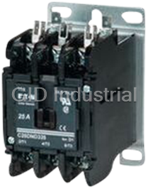
Cutler-Hammer C25DNF340 Contactors-40 Amp, 3-Pole, Definite Purpose Contactor, 600V Rated, Lug Termi...
Request a Quote

The quote request has been received
Close

Facing challenges or have inquiries? Feel free to contact us!
Call Us +1-469-283-2440
What they say about us
FANTASTIC RESOURCE
One of our top priorities is maintaining our business with precision, and we are constantly looking for affiliates that can help us achieve our goal. With the aid of GID Industrial, our obsolete product management has never been more efficient. They have been a great resource to our company, and have quickly become a go-to supplier on our list!
Bucher Emhart Glass
EXCELLENT SERVICE
With our strict fundamentals and high expectations, we were surprised when we came across GID Industrial and their competitive pricing. When we approached them with our issue, they were incredibly confident in being able to provide us with a seamless solution at the best price for us. GID Industrial quickly understood our needs and provided us with excellent service, as well as fully tested product to ensure what we received would be the right fit for our company.
Fuji
HARD TO FIND A BETTER PROVIDER
Our company provides services to aid in the manufacture of technological products, such as semiconductors and flat panel displays, and often searching for distributors of obsolete product we require can waste time and money. Finding GID Industrial proved to be a great asset to our company, with cost effective solutions and superior knowledge on all of their materials, it’d be hard to find a better provider of obsolete or hard to find products.
Applied Materials
CONSISTENTLY DELIVERS QUALITY SOLUTIONS
Over the years, the equipment used in our company becomes discontinued, but they’re still of great use to us and our customers. Once these products are no longer available through the manufacturer, finding a reliable, quick supplier is a necessity, and luckily for us, GID Industrial has provided the most trustworthy, quality solutions to our obsolete component needs.
Nidec Vamco
TERRIFIC RESOURCE
This company has been a terrific help to us (I work for Trican Well Service) in sourcing the Micron Ram Memory we needed for our Siemens computers. Great service! And great pricing! I know when the product is shipping and when it will arrive, all the way through the ordering process.
Trican Well Service
GO TO SOURCE
When I can't find an obsolete part, I first call GID and they'll come up with my parts every time. Great customer service and follow up as well. Scott emails me from time to time to touch base and see if we're having trouble finding something.....which is often with our 25 yr old equipment.
ConAgra Foods