

 Manufacturers
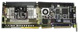
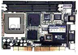
BOSER HS6037V1.2

Description
Full Size, All in one, CRT/Panel, Dual LAN, SCSI PC/104, WDT, DOC, CTA, RS-232/422/285, CTM, USB, IrDA, PICMG Industrial Single Board Computer
Part Number
HS6037V1.2
Price
Request Quote
Manufacturer
BOSER
Lead Time
Request Quote
Category
Single Board Computers
Specifications
System Chipset
Intel 82371AB
Form Factor
PICMG
Ethernet Chipset
Intel 82559
Video Chipset
C&T 69000
BIOS
Award PnP Flash BIOS
Board Type
Full Size
Bus Interface
PICMG Bus
Chipset
Intel 82443BX/82371
CPU
Socket 370 for Intel Celeron/Coppermine 300~MHz CPU
Dimensions
33.8(L) x 12.1(W) cm
FDD
Supports up to two floppy disk drives
I/O Chipset
Winbond W83977
LAN
Dual Intel 82559 10/100 Based LAN
Memory
Three DIMM sockets supporting up to 768MB
PCI Bridge
Intel 21152 or equivalent device
SCSI
Symbios 53C895 Ultra II SCSI controller
Datasheet

Extracted Text
HS-6037
™ ™
Socket 370 Celeron /Coppermine
• Full Size•All in one•CRT/Panel•Dual LAN•SCSI•PC/104•
• WDT•DOC•CTA•RS-232/422/485•CTM•USB•IrDA
• PICMG Industrial Single Board Computer•
HS-6037LLV
™ ™
Socket 370 Celeron /Coppermine
• Full Size•All in one•CRT/Panel•Dual LAN•PC/104•
• WDT•DOC•CTA•RS-232/422/485•CTM•USB•IrDA
PICMG Industrial Single Board Computer•
HS-6037LV
™ ™
Socket 370 Celeron /Coppermine
• Full Size•All in one•CRT/Panel•LAN•PC/104•
• WDT•DOC•CTA•RS-232/422/485•CTM•USB•IrDA
PICMG Industrial Single Board Computer•
HS-6037V
™ ™
Socket 370 Celeron /Coppermine
• Full Size•All in one•CRT/Panel•PC/104•
• WDT•DOC•CTA•CTM•USB•IrDA
PICMG Industrial Single Board Computer•
Copyrights
This manual is copyrighted and all rights are reserved. It is not allow any non
authorization in copied, photocopied, translated or reproduced to any electronic or
machine readable form in whole or in part without prior written consent from the
manufacturer.
In general, the manufacturer will not be liable for any direct, indirect, special,
incidental or consequential damages arising from the use of inability to use the
product or documentation, even if advised of the possibility of such damages.
The manufacturer keeps the rights in the subject to change the contents of this
manual without prior notices in order to improve the function design, performance,
quality and reliability. The author assumes no responsibility for any errors or
omissions, which may appear in this manual, nor does it make a commitment to
update the information contained herein.
Trademarks
BOSER is a registered trademark of BOSER Technology Co., Ltd.
Intel is a registered trademark of Intel Corporation.
Award is a registered trademark of Award Software, Inc.
ISB is a registered trademark of BOSER Technology Co., Ltd.
All other trademarks, products and or product's name mentioned herein are
mentioned for identification purposes only, and may be trademarks and/or registered
trademarks of their respective companies or owners.
© Copyright 2000
All Rights Reserved.
User Manual edition 2.5, June 03, 2003
Contents
HS-6037 ......................................................................................................1
HS-6037LLV ...............................................................................................1
HS-6037LV..................................................................................................1
HS-6037V....................................................................................................1
GENERAL INFORMATION .............................................................................3
1.1 MAJOR FEATURES .....................................................................................4
1.2 SPECIFICATIONS.........................................................................................5
1.3 DELIVERY PACKAGE...................................................................................7
HARDWARE INSTALLATION ........................................................................8
2.1 CAUTION OF STATIC ELECTRICITY.............................................................8
2.2 CAUTION ON UNPACKING AND BEFORE INSTALLATION .............................9
2.3 HS-6037’S LAYOUT.................................................................................10
2.4 QUICK LISTING OF JUMPERS ...................................................................11
2.5 QUICK LISTING OF CONNECTORS............................................................12
2.6 JUMPER SETTING DESCRIPTION..............................................................13
2.7 SETTING THE BUS CLOCK FREQUENCY...................................................14
2.8 SETTING THE RTC CONFIGURATION.......................................................14
2.9 SYSTEM MEMORY DRAM........................................................................14
2.10 SETTING THE FLAT PANEL VOLTAGE.....................................................15
2.11 WATCH-DOG TIMER...............................................................................15
2.12 SCSI CONTROLLER...............................................................................18
2.13 VGA CONTROLLER................................................................................18
2.14 DISKONCHIP ADDRESS SETTING.......................................................18
CONNECTION .................................................................................................20
3.1 POWER AND FAN CONNECTORS ............................................................20
3.2 IDE'S LED, KEY-LOCK AND RESET BUTTON..........................................21
3.3 EXTERNAL SPEAKER................................................................................22
3.4 PCI E-IDE DRIVE CONNECTOR..............................................................23
3.5 PARALLEL PORT CONNECTOR.................................................................25
3.6 THE FLOPPY DISK DRIVE CONNECTOR...................................................26
3.7 SERIAL PORTS CONNECTORS .................................................................27
3.8 KEYBOARD/MOUSE CONNECTORS ..........................................................29
Contents • i
3.9 VGA CONNECTORS.................................................................................31
3.10 IR CONNECTOR .....................................................................................33
3.11 USB CONNECTOR .................................................................................34
3.12 LAN INTERFACE CONNECTOR ..............................................................34
3.13 ULTRAⅡSCSI INTERFACE CONNECTOR..............................................36
3.14 ATX POWER CONTROLLER CONNECTOR .............................................37
AWARD BIOS SETUP....................................................................................38
4.1 MAIN MENU..............................................................................................39
4.2 STANDARD CMOS SETUP.......................................................................40
4.3 BIOS FEATURES SETUP..........................................................................41
4.4 CHIPSET FEATURES SETUP.....................................................................42
4.5 INTEGRATED PERIPHERALS .....................................................................43
4.6 POWER MANAGEMENT SETUP.................................................................45
4.7 PNP/PCI CONFIGURATION SETUP ..........................................................46
SOFTWARE UTILITIES .................................................................................47
5.1 VGA DRIVER INSTALL FOR WIN95&98....................................................48
5.2 VGA DRIVER INSTALL FOR WIN NT4.0 ..................................................51
5.3 NETWORK DRIVER INSTALL FOR WIN 95&98 .........................................55
5.4 NETWORK DRIVER INSTALL FOR WIN NT4.0..........................................58
5.5 ULTRA II SCSI INSTALL FOR WIN95&98 .................................................60
5.6 ULTRA II SCSI INSTALL FOR WIN NT4.0.................................................64
ii •Contents
Chapter-1
General Information
®
The HS-6037 is a 100MHz bus Intel BX chipset design PICMG bus Socket
TM TM
370 for Celeron™/Coppermine (Coppermine just for PCB V2.1)
Industrial Single Board (I.S.B.) CPU card with features combine together to
make it an ideal all-in-one industrial single board computer, enhanced I/O
effects with VGA, LAN and Ultra II SCSI interface.
With on board DMA33 of mode 4 to IDE drive interface architecture, the
HS-6037 supports with maximum 33.3 MB/sec in data transfer rating to two
®
IDE drive connection. Design with Intel 82443 BX core logic chipset
TM
supports all series Celeron™/Coppermine 300~850MHz CPU. On board
®
Intel 69000 VGA controller support up to 1280 x 1024 256 colors display
resolution. And it also provides one internal 50pin connector for various type
of the LCD Panel connection.
The advanced PICMG bus add-on connection of HS-6037 allows user could
easily obtain both ISA's 16bit and PCI's 32bit full set signals from a full size
PICMG slot for suitable plug into a any size system with 8/16/32-bit ISA
and-or PCI slots operating. The HS-6037 provides with three 168pin DIMM
sockets support up to 768MBytes of main system memory.
A single Flash chip holds the system BIOS, and you can easy update the
Flash BIOS by the Utility Update. Advanced USB and IR ports also provide
for faster and easily in data transmission. You can also use the DOS version
of the "DiskOnChip" socket by issuing commands from the DOS prompt
without the necessity of other software supports up to 144MB.
®
The HS-6037 features include two Intel 82559 10/100-Based LAN design
on board. With one external RJ45 and two 10 pin header connector provides
an easily for user’s LAN application.
If a non-expect program cause halts, the onboard watchdog timer will
automatically reset the CPU or generate an interrupt. The watchdog is
designed with hardware only and doesn’t need any arithmetical functions of a
real-time clock chip. This ensures the reliability in an unmanned or
standalone system.
3
1.1 Major Features
® TM TM
� Socket 370 for Intel Celeron /Coppermine 300~850MHz CPU
� Three DIMM sockets provides up to 768MB
� Fast PCI DMA33 controller support four IDE disk drives
� 100MHz system clock rate
� PnP I/O address & IRQ selection
� One RS-232 and one RS-232/422/485 serial ports include 16C550
UART with 16byte FIFO
� One enhanced bi-directional parallel port supports SPP/ECP/EPP
� On board PS/2 Keyboard and PS/2 Mouse connector
� On board Winbond W83977 super I/O chipset
� On board 69000 CRT/Panel display controller
®
� On board Dual Intel 82559 100 Based LAN
� On board Symbios 53C895 Ultra II SCSI
� On board PCI Bridge
� DiskOnChip memory size up to 144MB
� PC/104 Bus connector
� ATX Power Function support
� CPU Temperature Alarm Function support
� CPU Temperature Monitor Function support
*It will be a Warning “beep” come out if the CPU’s temperature reached
60℃±5%. And it will stop as the CPU’s temperature going down below
60℃±5% again.
4
1.2 Specifications
® TM TM
� CPU:Socket 370 for Intel Celeron /Coppermine
300~850MHz CPU
� Bus Interface:PICMG Bus
� Memory:Three DIMM sockets provides up to 768MB
®
� Chipset:Intel 82443BX
� I/O Chipset:Winbond W83977
®
� PCI Bridge:Intel 21152 or equivalent device
� VGA:69000 with 2MB memory support CRT/Panel display up to
1280x1024x256 colors
� IDE:Four IDE disk drives support DMA33 transfer rate up to
33MB/sec
� Floppy:Support up to two floppy disk drives
� Parallel Port:Support SPP/ECP/EPP
®
� Dual LAN:Dual Intel 82559 100 Based LAN
� SCSI:Symbios 53C895 Ultra II SCSI
� Serial Port:One RS-232 and one RS-232/422/485 serial ports
include 16C550 UART with 16byte FIFO
� PC/104:PC/104 connector for 16bit ISA Bus
� IR:One IrDA TX/RX header
� USB:Support two USB ports
� Keyboard:PS/2 6pin Mini Din or 5pin header
� Mouse:PS/2 6pin Mini Din or 4pin header
� DiskOnChip:Socket for DiskOnChip and memory size up to
144MB
� BIOS:Award Y2K PnP Flash BIOS
5
� Watch-Dog Timer:Set 1, 2, 10, 20, 110, 220 seconds activity
trigger with Reset or NMI
� CMOS:DS12C887 or equivalent device
� DMA Channels:7
� Interrupt Levels:15
� Extra Power:One 4pin +5V+12V connector
� Power Voltage:+5V, +12V, -12V
� Maximum Power Consumption:+5V@6.2A(800MHz),
+12V@120mA, -12V@50mA
� Operating Temperature:0~60℃
� CPU Temperature Alarm:Beeping alarm when CPU’s
temperature over heating limited
� CPU Temperature Monitor:LM75 or equivalent device
� Board Size:13.26” (L) x 4.8”(W)
The HS-6037 provides with VGA CRT-LCD Interface, supports DMA33, WDT,
DOC, DUAL LAN, UltraⅡSCSI, USB and IrDA.
The HS-6037LLV provides with VGA CRT-LCD Interface, supports DMA33,
WDT, DOC, USB, DUAL LAN and IrDA. ( A version without SCSI of HS-6037).
The HS-6037LV provides with VGA CRT-LCD Interface support DMA33, WDT,
DOC, LAN, USB and IrDA. ( A version without one LAN and SCSI of HS-6037).
The HS-6037V provides with VGA CRT-LCD Interface support DMA33, WDT,
DOC, USB and IrDA. ( A version without two LAN ,SCSI and RS-232/422/485 of
HS-6037 ).
6
1.3 Delivery Package
The delivery package of HS-6037 includes all following items:
� One HS-6037 Industrial Single Board
� One Printer Ports Bracketed Flat Cable
� One com port Bracketed Flat Cable
� One IDE port Flat Cable
� One FDD port Flat Cable
� One PS/2 to Standard DIN type Keyboard Transfer Cable
� Two LAN Cable
� Utility CD
� User’s Manual
Please contact with your dealer if any of these items are missing or
damaged when purchasing. And please keep all parts of the
delivery package with packing materials in case of you want to ship
or store the product in feature.
7
Chapter-2
Hardware Installation
This chapter provides the information on how to install the hardware
of HS-6037. At first, please follow up sections 1.3, 2.1 and 2.2 in
check the delivery package and carefully unpacking. Following
after, the jumpers setting of switch, watchdog timer and the
DiskOnChip address selection etc.
2.1 Caution of Static Electricity
The HS-6037 has been well package with an anti-static bag in
protect its sensitive computer components and circuitry from the
damage of static electric discharge.
Note: DO NOT TOUCH THE BOARD OR ANY OTHER
SENSITIVE COMPONENTS WITHOUT ALL NECESSARY
ANTI-STATIC PROTECTION.
You should follow the steps as following to protect the board in
against the static electric discharge whenever you handle the
board:
1. Please use a grounding wrist strap on whoever needs to handle
the HS-6037. Well clip the ALLIGATOR clip of the strap to the end
of the shielded wire lead from a grounded object. Please put on
and connect the strap before handle the HS-6037 for harmlessly
discharge any static electricity through the strap.
2. Please use anti-static pad for put any components or parts or
tools on the pad whenever you work on them outside the
computer. You may also in use the anti-static bag instead the
pad. Please ask from your local supplier in help up your
necessary parts on anti-static requirement.
8
2.2 Caution on Unpacking and Before Installation
First of all, please follow with all necessary steps of section 2.1 in
protection the HS-6037 from electricity discharge. With refer to
section 1.3, please check the delivery package again with following
steps:
1. Unpacking the HS-6037, keep well storage of all packing material,
manual and diskette etc. if has.
2. Is there any components lose or drop from the board? DO NOT
INSTALL IF HAPPENED.
3. Is there any visual damaged of the board? DO NOT INSTALL IF
HAPPENED.
4. Well check from your optional parts (i.e. CPU, SRAM, DRAM,
ROM-Disk etc.) for completed setting all necessary jumpers
setting to jumper pin-set and CMOS setup correctly. Please also
reference to all information of jumpers setting in this manual.
5. Well check from your external devices (i.e. Add-On-Card, Driver
Type etc.) for completed add-in or connection and CMOS setup
correctly. Please also reference to all information of connector
connection in this manual.
6. Please keep all necessary manual and diskette in a good
condition for your necessary re-installation if you change your
Operating System or whatever needs.
9
2.3 HS-6037’s Layout
10
2.4 Quick Listing of Jumpers
JP1 � RESET..................................................................... P.21
JP3 � BASE CLOCK FREQUENCY SETTING .......................... P.14
JP5 � PANEL VOLTAGE SELECT.......................................... P.15
JP6 � CMOS CLEAR (DS12B887 ONLY) ........................... P.14
JP7 � RS-422/485 RECEIVER SELECT............................... P.27
JP9 � RS-422/485 TRANSCEIVER SELECT ......................... P.27
JP10/JP11 � RS-232 OR RS-422/485 SELECT ............................ P.27
JP12(5-10) � DISKONCHIP ADDRESS SELECT............................... P.15
JP12(1-4) � WDT TIMER SELECT................................................ P.19
JP13 � WDT ACTIVE SELECT .............................................. P.15
JP14/JP15 � LAN1/LAN2 ENABLE/DISABLED SELECT
JP24 � VGA ENABLE/DISABLED SELECT .............................. P.18
JP25 � SCSI ENABLE/DISABLED SELECT............................. P.18
11
2.5 Quick Listing of Connectors
S1 � ATX POWER SWITCH
CN3 � SPEAKER ................................................................... P.22
CN4 � IDE LED CONNECTOR ............................................... P.21
CN5 � 5PIN KEYBOARD CONNECTOR...................................... P.29
CN6 � FAN CONNECTOR....................................................... P.20
CN7(1-2) � POWER LED .............................................................. P.21
CN7(3-5) � KEYLOCK.................................................................... P.21
CN8 � IR .............................................................................. P.23
CN9 � 4PIN POWER CONNECTOR ........................................... P.20
CN10 � PRIMARY IDE CONNECTOR ......................................... P.23
CN11 � SECONDARY IDE CONNECTOR.................................... P.23
CN12 � SCSI CONNECTOR ..................................................... P.36
CN13 � ATX POWER CONNECTOR
CN14 � ATX FUNCTION CONNECTOR ...................................... P.37
CN15 � FDD CONNECTOR ...................................................... P.26
CN16 � PANEL CONNECTOR.................................................... P.31
CN17 � PC/104 64PIN CONNECTOR
CN18 � PC/104 40PIN CONNECTOR
CN19 � PARALLEL PORT CONNECTOR ..................................... P.25
CN20 � RS-422/485 CONNECTOR .......................................... P.27
CN21 � USB CONNECTOR
CN22 � COM1 (5X2 HEADER) ................................................ P.27
CN23 � COM2 (5X2 HEADER) ................................................ P.27
CN24 � LAN1 10PIN CONNECTOR (5X2 HEADER).................... P.34
CN25 � LAN2 10PIN CONNECTOR (5X2 HEADER).................... P.34
CN26 � 10PIN VGA CONNECTOR (5X2 HEADER) ..................... P.31
CN27 � LAN1 RJ45 CONNECTOR........................................... P.34
CN28 � 4PIN MOUSE CONNECTOR ........................................... P.29
CN29 � PS/2 6PIN MINI DIN MOUSE CONNECTOR ..................... P.29
CN30 � DB15 VGA CONNECTOR............................................. P.31
CN31 � PS/2 6PIN MINI DIN KEYBOARD CONNECTOR ............. P.29
CN32 � COM1 (DB9) ............................................................. P.27
CN33 � COM2 (DB9) ............................................................. P.27
12
2.6 Jumper Setting Description
A jumper pin-set is ON as a shorted circuit with a plastic cap
inserted over two pins. A jumper pin-set is OFF as a open circuit
with a plastic cap inserted over one or no pin(s) between pins. The
below figure 2.2 shows the examples of different jumper pin-set
setting as ON or OFF in this manual.
Figure 2.2
All jumper pin-set already has its default setting with the plastic cap
inserted as ON, or without the plastic cap inserted as OFF. The
default setting may reference in this manual with a " * " symbol in
front of the selected item.
13
2.7 Setting the Bus Clock Frequency
The HS-6037 provides all necessary by jumper setting in using Bus
Clock frequency as the system bus clocking with JP3 setting as
following:
� Bus Clock Frequency Setting of JP3 :
Bus Clock Frequency JP3
*66MHz ON
100MHz OFF
® TM
PS:Pentium III FC-PGA Coppermine Processor 100MHz FSB, please set JP3 off.
2.8 Setting the RTC Configuration
The HS-6037 provides a setting for the selection of the RTC Clear
Jumper by JP6 setting as following:
� CMOS Setting of JP6:(DS12B887 only)
CMOS Clear Jumper JP6
Normal * OFF
Clear CMOS ON
2.9 System Memory DRAM
The HS-6037 provides a wide SDRAM memory by three DIMM
sockets (DIM1, DIM2, DIM3) request the access time should meet
PC100 standard. The maximum capacity of the on board memory is
768MBytes.
14
2.10 Setting the Flat Panel Voltage
The HS-6037 provides a setting for the selection of the working
voltage of individual flat panel by JP5 setting as following:
� Flat Panel Voltage Selecting of JP5:
Panel’s Working Voltage JP5
5.0 V 1-2
* 3.3 V 2-3
Please contact with your flat panel supplier for make sure a correct
Panel’s Working Voltage. Any mistake will cause defect to your flat
panel.
2.11 Watch-Dog Timer
There are three access cycles of Watch-Dog Timer as Enable,
Refresh and Disable. The Enable cycle should proceed by READ
PORT 443H. The Disable cycle should proceed by READ PORT
045H. A continue Enable cycle after a first Enable cycle means
Refresh.
Once if the Enable cycle activity, a Refresh cycle is request before
the time-out period for restart counting the WDT Timer's period.
Otherwise, it will assume that the program operation is abnormal
when the time counting over the period preset of WDT Timer. A
System Reset signal to start again or a NMI cycle to the CPU comes
if over.
The JP13 is using for select the active function of watch-dog timer in
disable the watch-dog timer, or presetting the watch-dog timer
activity at the reset trigger, or presetting the watch-dog timer activity
at the NMI trigger.
15
� JP13 : WDT Active Type Setting
JP13 DESCRIPTION
*2-3 System Reset
1-2 Active NMI
OFF Disable Watch-Dog Timer
The WDT is disabled after the system Power On. The WDT can be
enabled by a Enable cycle with reading the control port (443H), a
Refresh cycle with reading the control port (443H) and a Disable
cycle by reading the WDT disable control port (045H). After a
Enable cycle of WDT, user must constantly proceed a Refresh cycle
to WDT before its period setting comes ending of every 1, 2, 10, 20,
110 or 220 seconds which pre-setting by JP12. If the Refresh cycle
does not active before WDT period cycle, the on board WDT
architecture will issue a Reset or NMI cycle to the system.
� JP12(5-10) : Select WDT Preiod
PERIOD 5-6 7-8 9-10
*1 sec ON ON ON
2 sec OFF ON ON
10 sec ON OFF ON
20 sec OFF OFF ON
110 sec ON ON OFF
220 sec OFF ON OFF
The Watch-Dog Timer is controlled by two I/O ports.
443H I/O Read The Enable cycle
443H I/O Read The Refresh cycle
045H I/O Read The Disable cycle
The following sample programs showing how to Enable, Disable
and Refresh the WDT:
16
WDT_EN_RF EQU 0443H
WDT_DIS EQU 0045H
WT_Enable PUSH AX ; keep AX DX
PUSH DX
MOV DX,WDT_EN_RF ; enable the watch-dog timer
IN AL,DX
POP DX ; get back AX, DX
POP AX
RET
WT_Rresh PUSH AX ; keep AX, DX
PUSH DX
MOV DX,WDT_ET_RF ; refresh the watch-dog
timer
IN AL,DX
POP DX ; get back AX, DX
POP AX
RET
WT_DISABLE PUSH AX
PUSH DX
MOV DX,WDT_DIS ; disable the watch-dog
timer
IN AL,DX
POP DX ; get back AX, DX
POP AX
RET
17
2.12 SCSI Controller
The HS-6037 provides SYMBIOS Ultra II SCSI Controller transferred
rate up to 80 Mbytes/Sec, and can drive up to 15 set SCSI HDD. A JP25
is using for select the enable or disable function of SCSI control.
� JP25 : SCSI Enable/Disable Select
JP25 DESCRIPTION
1-2 Enable
* 2-3 Disable
2.13 VGA Controller
The HS-6037 has built in a 69000 VGA Controller with 2 MB
memory, support resolutions up to 1280 x 1024 x 256 colors,
reserved internal 50pin Panel connector.
� JP24 : VGA Enable/Disable Select
JP24 DESCRIPTION
1-2 Enable
2-3 Disable
2.14 DiskOnChip Address Setting
The HS-6037 provides a U17 socket for install the DiskOnChip
module.
A JP12 may select the starting memory address of the
DiskOnChip (D.O.C.) for avoid the mapping area with any other
memory devices. If you have another extra memory devices in the
system with the same memory, neither the HS-6037 nor the extra
memory devices will function normally. Please setting both at
different memory address mapping.
18
� JP12(1-4) : DiskOnChip Address Select
Memory Address Mapping 1-2 3-4
*D000 ON ON
D800 ON OFF
E000 OFF ON
*) : default setting
The D.O.C. function allows the system in using without FDD nor
HDD. The D.O.C. may formatting as driver C: or driver A: User may
also easily uses the DOS's commands such as FORMAT, SYS,
COPY, XCOPY, DISCOPY and DISKCOMP etc. This is means that
the D.O.C. may uses as driver-A if the system without FDD-A for
ambient application. Please contact with your supplier for different
size D.O.C. module.
19
Chapter-3
Connection
This chapter gives all necessary information of the peripheral's
connections, switches and indicators.
3.1 Power and FAN Connectors
The HS-6037 provides one 4pin DC Power connector as following
CN9 pin information. And also provides one 3pin fan out connector
as following CN6 pin information.
� CN9 : 4pin Power Connector
PIN NO. DESCRIPTION
1 +12V
2 GND
3 GND
4 VCC
� CN6 : 3pin FAN Connector
PIN NO. DESCRIPTION
1 GND
2 +12V
3 N.C.
20
3.2 IDE's LED, Key-Lock and Reset Button
The HS-6037 has one LED ( D1 ) indicates out power on status.
And the following provides the pin information for IDE's LED
indicator, Keylock and Reset Button connections from CN4, CN7
and JP1.
� CN4 : IDE LED Connector
PIN NO. DESCRIPTION
1 HDD Active#
2 +5V
� CN7 : Power LED & Keylock
PIN NO. DESCRIPTION
1 Power LED Anode
2 N/C
3 GND
4 Keylock
5 GND
� JP1 : Reset Button
PIN NO. DESCRIPTION
1 GND
2 External Reset
21
3.3 External Speaker
The HS-6037 has an on board buzzer (BZ1). And it also provides
the CN3 in allows user to connecting to the external speaker.
� CN3 : Speaker Connector
PIN NO. DESCRIPTION
1 SPEAKER SIGNAL
2 NC
3 GROUND
4 +5V
22
3.4 PCI E-IDE Drive Connector
Two standard 40pin header daisy-chain driver connector provides
as CN10 and CN11 with following pin assignment. Total four IDE
(Integrated Device Electronics) drivers may connect.
� CN10: Primary IDE Connector
PIN NO. DESCRIPTION PIN NO. DESCRIPTION
1 RESET 2 GND
3 DATA 7 4 DATA 8
5 DATA 6 6 DATA 9
7 DATA 5 8 DATA 10
9 DATA 4 10 DATA 11
11 DATA 3 12 DATA 12
13 DATA 2 14 DATA 13
15 DATA 1 16 DATA 14
17 DATA 0 18 DATA 15
19 GND 20 N/C
21 N/C 22 GND
23 IOW# 24 GND
25 IOR# 26 GND
27 N/C 28 BALE - DEFAULT
29 N/C 30 GROUND# -DEFAULT
31 INTERRUPT 32 IOCS16#-DEFAULT
33 SA1 34 N/C
35 SA0 36 SA2
37 HDC CS0 38 HDC CS1#
39 HDD ACTIVE 40 GND
23
� CN11: Secondary IDE Connector
PIN NO. DESCRIPTION PIN NO. DESCRIPTION
1 RESET 2 GND
3 DATA 7 4 DATA 8
5 DATA 6 6 DATA 9
7 DATA 5 8 DATA 10
9 DATA 4 10 DATA 11
11 DATA 3 12 DATA 12
13 DATA 2 14 DATA 13
15 DATA 1 16 DATA 14
17 DATA 0 18 DATA 15
19 GND 20 N/C
21 N/C 22 GND
23 IOW# 24 GND
25 IOR# 26 GND
27 N/C 28 BALE - DEFAULT
29 N/C 30 GROUND# -DEFAULT
31 INTERRUPT 32 IOCS16#-DEFAULT
33 SA1 34 N/C
35 SA0 36 SA2
37 HDC CS0 38 HDC CS1#
39 HDD ACTIVE 40 GND
24
3.5 Parallel Port Connector
A standard 26pin flat cable driver connector provides as CN19 with
following pin assignment for connection to parallel printer.
� CN19: Parallel Port Connector
PIN NO. DESCRIPTION PIN NO. DESCRIPTION
1 STROBE 2 DATA 0
3 DATA 1 4 DATA 2
5 DATA 3 6 DATA 4
7 DATA 5 8 DATA 6
9 DATA 7 10 ACKNOWLEDGE
11 BUSY 12 PAPER EMPTY
13 PRINTER SELECT 14 AUTO FORM FEED
15 ERROR# 16 INITIALIZE
17 PRINTER SELECT LN# 18 GND
19 GND 20 GND
21 GND 22 GND
23 GND 24 GND
25 GND 26 GND
25
3.6 The Floppy Disk Drive Connector
A standard 34pin header daisy-chain driver connector provides as
CN15 with following pin assignment. Total two FDD drivers may
connect.
� CN15 : FDD Connector
PIN NO. DESCRIPTION PIN NO. DESCRIPTION
1 GND 2 REDUCE WRITE
3 GND 4 N/C
5 GND 6 N/C
7 GND 8 INDEX#
9 GND 10 MOTOR ENABLE A#
11 GND 12 DRIVE SELECT B#
13 GND 14 DRIVE SELECT A#
15 GND 16 MOTOR ENABLE B#
17 GND 18 DIRECTION#
19 GND 20 STEP#
21 GND 22 WRITE DATA#
23 GND 24 WRITE DATA#
25 GND 26 TRACK 0#
27 GND 28 WRITE PROTECT#
29 GND 30 READ DATA#
31 GND 32 SIDE 1 SELECT
33 GND 34 DISK CHANGE#
26
3.7 Serial Ports Connectors
The HS-6037 offers two high speed NS16C550 compatible UART
with Read/Receive 16 byte FIFO serial ports with two internal 10pin
header. The HS-6037P which is with two external DB9 connectors
without VGA nor LAN on board. All pin-assignment are listing at
below:
� CN32/33 : COM1/COM2 Serial Connector (DB9)
PIN NO. DESCRIPTION
1 DATA CARRIER DETECT (DCD)
2 RECEIVE DATA (RXD)
3 TRANSMIT DATA (TXD)
4 DATA TERMINAL READY (DTR)
5 GND (GND)
6 DATA SET READY (DSR)
7 REQUEST TO SEND (RTS)
8 CLEAR TO SEND (CTS)
9 RING INDICATOR (RI)
� CN22/23 : COM1/COM2 Serial Connector (5x2 Header)
PIN NO. DESCRIPTION PIN NO. DESCRIPTION
1 DCD 2 DSR
3 RXD 4 RTX
5 TXD 6 CTX
7 DTR 8 RI
9 GND 10 N/C
The HS-6037 also provides one RS-422/485 port, the CN20 for use as
an RS-422/485. Please reference to the following for setting JP7, JP9,
JP10 and JP11 at enable or disable the RS-422/485 function.
� JP10/JP11 : RS-232/422/485 Select
Jumper RS232 RS-422/485
JP10 3-5, 4-6 ON 1-3 ,2-4 ON
JP11 3-5, 4-6 ON 1-3, 2-4 ON
27
� CN20 : RS-422/485 Connector
PIN NO. DESCRIPTION PIN NO. DESCRIPTION
1 -TX 2 +TX
3 +RX 4 -RX
5 GND 6 -RTS
7 +RTS 8 +CTS
9 -CTS 10 N/C
� JP7 : Receiver Enable Control
JP7 DESCRIPTION
1-2 ON Always Enable
3-4 ON Enable by writing the REG : 2 EFH BIT1=1
*1-2 OFF Always Disable
� JP9 : Transceiver Enable Control
JP9 DESCRIPTION
1-2 ON Always Enable
3-4 ON Enable by ”-RTS” signal
5-6 ON Enable by writing the REG : 2 EFH BIT0=1
*ALL OFF Always Disable
28
3.8 Keyboard/Mouse Connectors
The HS-6037 offers two possibilities for keyboard connections to
external PS/2 type keyboard at CN31, or an internal 5pin header at
CN5.
� CN5: 5pin Keyboard Connector
PIN NO. DESCRIPTION
1 KEYBOARD CLOCK
2 KEYBOARD DATA
3 N/C
4 GND
5 +5V
� CN31 : PS/2 6pin Mini Din Keyboard Connector
PIN NO. DESCRIPTION
1 KEYBOARD DATA
2 N/C
3 GND
4 +5V
5 KEYBOARD CLOCK
6 N/C
The HS-6037 provides an external PS/2 mouse connector at CN29
and Internal 4pin mouse connector at CN28 with following pin
information.
29
� CN29 : PS/2 6pin Mini Din Mouse Connector
PIN NO. DESCRIPTION
1 DATA
2 N/C
3 GND
4 +5V
5 CLK
6 N/C
� CN28 : 4pin Mouse Connector
PIN NO. DESCRIPTION
1 CLK
2 DATA
3 VCC
4 GND
30
3.9 VGA Controller
The HS-6037 provides three possible connectives of VGA connections. One
standard DB15 external VGA connector as following CN30 pin information.
Another header is 5X2 internal VGA connector. Others internal 50pin header
for LCD Panel connection as following CN16 pin information.
� CN16 : 50pin Internal LCD Panel Connector
PIN NO. DESCRIPTION PIN NO. DESCRIPTION
1 +12V 2 +12V
3 GND 4 GND
Note-1
5 3.3V / 5V 6 ENAVDD
7 ENAVEE 8 GND
9 P0 10 P1
11 P2 12 P3
13 P4 14 P5
15 P6 16 P7
17 P8 18 P9
19 P10 20 P11
21 P12 22 P13
23 P14 24 P15
25 P16 26 P17
27 P18 28 P19
29 P20 30 P21
31 P22 32 P23
33 P24 34 P25
35 SHFCLK 36 FP
37 M 38 LP
39 GND 40 FPBACK
41 P26 42 P27
43 P28 44 P29
45 P30 46 P31
47 P32 48 P33
49 P34 50 P35
Note-1: Please setting the voltage correctly of individual panel by JP5.
31
Flat Panel Display Interface
Mono Color
HS-6037
STN- STN- STN- STN- STN-D STN-D
SS DD DD TFT TFT TFT TFT
HR SS SS DD D D
PIN Pin 9/12/16 18 18/24 36-bit 18/24 8-bit 16-bit 8-bit 16-bit
8-bit 8-bit 16-bit 24-bit
# Name bit bit bit bit (4bP) (4bP) (4bP) (4bP)
9 P0 D0 UD3 UD7 B0 B0 FB0 FB0 R1 R1 UR1 UR0 UR0
10 P1 D1 UD2 UD6 B1 B1 FB1 FB1 B1 G1 UG1 UG0 UG0
11 P2 D2 UD1 UD5 B2 B0 B2 FB2 FB2 G2 B1 UB1 UB0 UB0
12 P3 D3 UD0 UD4 B3 B1 B3 FB3 FB3 R3 R2 UR2 UR1 LR0
13 P4 D4 UD3 UD3 B4 B2 B4 FB4 SB0 B3 G2 LR1 UR0 LG0
14 P5 D5 UD2 UD2 G0 B3 B5 FB5 SB1 G4 B2 LG1 LG0 LB0
15 P6 D6 UD1 UD1 G1 B4 B6 SB0 SB2 R5 R3 LB1 LB0 UR1
16 P7 D7 UD0 UD0 G2 B5 B7 SB1 SB3 B5 G3 LR2 LR1 UG1
17 P8 UD7 G3 G0 SB2 FG0 B3 UG1 UB1
18 P9 UD6 G4 G1 SB3 FG1 R4 UB1 LR1
19 P10 UD5 G5 G0 G2 SB4 FG2 G4 UR2 LG1
20 P11 UD4 R0 G1 G3 SB5 FG3 B4 UG2 LB1
21 P12 UD3 R1 G2 G4 FG0 SG0 R5 LG1 UR2
22 P13 UD2 R2 G3 G5 FG1 SG1 G5 LB1 UG2
23 P14 UD1 R3 G4 G6 FG2 SG2 B5 LR2 UB2
24 P15 UD0 R4 G5 G7 FG3 SG3 R6 LG2 LR2
25 P16 R0FG4FR0 LG2
26 P17 R1FG5FR1 LB2
27 P18 R0 R2 SG0FR2 UR3
28 P19 R1 R3 SG1FR3 UG3
29 P20 R2 R4 SG2SR0 UB3
30 P21 R3 R5 SG3SR1 UR3
31 P22 R4 R6 SG4SR2 LG3
32 P23 R5 R7 SG5SR3 LB3
33 P24 FR0
34 P25 FR1
41 P26 FR2
42 P27 FR3
43 P28 FR4
44 P29 FR5
45 P30 SR0
46 P31 SR1
47 P32 SR2
48 P33 SR3
49 P34 SR4
50 P35 SR5
35 SHFCLK: Pixel clock .Shift Clock
36 FLM.VSYNC: First line marker
37 M, DE: Panel AC driver control
38 LP, HSYNC: Latch pulse
40 ENABKL: Power sequencing control for enabling the back-light.(high active)
32
� CN26 : 10pin VGA Connector (5x2 Header)
PIN NO. DESCRIPTION PIN NO. DESCRIPTION
1 RED 2 GND
3 GREEN 4 GND
5 BLUE 6 GND
7 HSYNC 8 GND
9 VSYNC 10 GND
� CN30 : 15pin VGA connector (DB15)
PIN NO. DESCRIPTION PIN NO. DESCRIPTION
1 RED 2 GREEN
3 BLUE 4 N/C
5 GND 6 GND
7 GND 8 GND
9 N/C 10 GND
11 N/C 12 N/C
13 HSYNC 14 VSYNC
15 N/C
3.10 IR Connector
The HS-6037 provides a 5pin internal IR communication connector
as following CN8 pin information.
� CN8 : 5pin IR Connector
PIN NO. DESCRIPTION
1 VCC
2 FIRRX
3 IRRX
4 GND
5 IRTX
33
3.11 USB Connector
The HS-6037 provides two 8pin USB ports. Please refer to the
following detail pin information.
� CN21: 8pin USB Connector
PIN NO. CN21 PIN NO. CN21
1 VCC 2 VCC
3 BD0- 4 BD1-
5 BD0+ 6 BD1+
7 GND 8 GND
3.13 LAN Interface Connector
The HS-6037 provides one external (RJ45) and two internal
(Header 5x2) 10/100-based LAN interface connector. Please refer
to the following detail of pin information.
� CN27 : LAN1 RJ-45 Connector
PIN NO. CN22
1 TX+
2 TX-
3 RX+
4 N/C
5 N/C
6 RX-
7 N/C
8 N/C
9 GND
LAN1: There are three LED indicators provide the running
conditions of the LAN with JP17, JP18 and JP19:
JP17: LINK LED
JP18: ACTIVE LED
JP19: SPEED LED
34
CN24/CN25: LAN1/LAN2 10pin Connector (5x2 Header)
PIN NO. CN24/CN25
1 VCC
2 LINK
3 RX+
4 RX-
5 ACT
6 GND
7 SPEED
8 GND
9 TX+
10 TX-
LAN2: There are three LED indicators provide the running
conditions of the LAN with JP20, JP21 and JP22
JP20: LINK LED
JP21: ACTIVE LED
JP22: SPEED LED
35
3.13 UltraⅡSCSI Interface Connector
This HS-6037 provides two internal UltraⅡ SCSI connector for all
kinds of user application and easy connection, one 68pin female D
Sub connector for 16bits UltraⅡ SCSI port. Please reference to the
following for detail pin assignment.
Pin CN12 Pin CN12
1 +SD12 35 -SD12
2 +SD13 36 -SD13
3 +SD14 37 -SD14
4 +SD15 38 -SD15
5 +SDP1 39 -SDP1
6 +SD0 40 -SD0
7 +SD1 41 -SD1
8 +SD2 42 -SD2
9 +SD3 43 -SD3
10 +SD4 44 -SD4
11 +SD5 45 -SD5
12 +SD6 46 -SD6
13 +SD7 47 -SD7
14 +SDP0 48 -SDP0
15 GND 49 GND
16 DIFFSEN 50 N/C
17 TPW-EX 51 TPW-EX
18 TPW-EX 52 TPW-EX
19 N/C. 53 N/C.
20 GND 54 GND
21 +SATN 55 -SATN
22 GND 56 GND
23 +SBSY 57 -SBSY
24 +SACK 58 -SACK
25 +SRST 59 -SRST
26 +SMSG 60 -SMSG
27 +SSEL 61 -SSEL
28 +SCD 62 -SCD
29 +SREQ 63 -SREQ
30 +SIO 64 -SIO
31 +SD8 65 -SD8
32 +SD9 66 -SD9
33 +SD10 67 -SD10
34 +SD11 68 -SD11
36
3.14 ATX Power Controller Connector
The HS-6037 support ATX Power function by CN14. The connector of
CN14 can control the 5 pin ATX Power via the extension cable from the
Backplane (from the version 6.1).
37
Chapter-4
AWARD BIOS Setup
The HS-6037 uses the Award PCI/ISA BIOS for the system
configuration. The Award BIOS setup program is designed to
provide the maximum flexibility in configuring the system by offering
various options which could be selected for end-user requirements.
This chapter is written to assist you in the proper usage of these
features.
To access AWARD PCI/ISA BIOS Setup program, press key.
The Main Menu will be displayed at this time.
38
4.1 Main Menu
Once you enter the Award BIOS CMOS Setup Utility, the Main
Menu will appear on the screen. The Main Menu allows you to
select from several setup functions and two exit choices. Use the
arrow keys to select among the items and press
Frequently asked questions
How does Industrial Trading differ from its competitors?

Is there a warranty for the HS6037V1.2?
Which carrier will Industrial Trading use to ship my parts?
Can I buy parts from Industrial Trading if I am outside the USA?
Which payment methods does Industrial Trading accept?
Why buy from GID?

Quality
We are industry veterans who take pride in our work

Protection
Avoid the dangers of risky trading in the gray market

Access
Our network of suppliers is ready and at your disposal

Savings
Maintain legacy systems to prevent costly downtime

Speed
Time is of the essence, and we are respectful of yours
Related Products

Boser 251-10301001 CPU Board with 1U high CPU cooler for PGA 478 1.7~2.4GHz CPU for HS-4701
Pentium II/III Slot 1 Full-size Board with VGA & LAN

Intel Pentium 4 processor PICMG Bus SBC with VGA, Audio, Dual LAN & USB2.0
Intel Pentium 4 processor PICMG Bus SBC with VGA, Audio, Dual LAN & USB2.0
Request a Quote

The quote request has been received
Close

Facing challenges or have inquiries? Feel free to contact us!
Call Us +1-469-283-2440
What they say about us
FANTASTIC RESOURCE
One of our top priorities is maintaining our business with precision, and we are constantly looking for affiliates that can help us achieve our goal. With the aid of GID Industrial, our obsolete product management has never been more efficient. They have been a great resource to our company, and have quickly become a go-to supplier on our list!
Bucher Emhart Glass
EXCELLENT SERVICE
With our strict fundamentals and high expectations, we were surprised when we came across GID Industrial and their competitive pricing. When we approached them with our issue, they were incredibly confident in being able to provide us with a seamless solution at the best price for us. GID Industrial quickly understood our needs and provided us with excellent service, as well as fully tested product to ensure what we received would be the right fit for our company.
Fuji
HARD TO FIND A BETTER PROVIDER
Our company provides services to aid in the manufacture of technological products, such as semiconductors and flat panel displays, and often searching for distributors of obsolete product we require can waste time and money. Finding GID Industrial proved to be a great asset to our company, with cost effective solutions and superior knowledge on all of their materials, it’d be hard to find a better provider of obsolete or hard to find products.
Applied Materials
CONSISTENTLY DELIVERS QUALITY SOLUTIONS
Over the years, the equipment used in our company becomes discontinued, but they’re still of great use to us and our customers. Once these products are no longer available through the manufacturer, finding a reliable, quick supplier is a necessity, and luckily for us, GID Industrial has provided the most trustworthy, quality solutions to our obsolete component needs.
Nidec Vamco
TERRIFIC RESOURCE
This company has been a terrific help to us (I work for Trican Well Service) in sourcing the Micron Ram Memory we needed for our Siemens computers. Great service! And great pricing! I know when the product is shipping and when it will arrive, all the way through the ordering process.
Trican Well Service
GO TO SOURCE
When I can't find an obsolete part, I first call GID and they'll come up with my parts every time. Great customer service and follow up as well. Scott emails me from time to time to touch base and see if we're having trouble finding something.....which is often with our 25 yr old equipment.
ConAgra Foods