

 Manufacturers
BOSCH REXROTH VT 3000-3X
Description
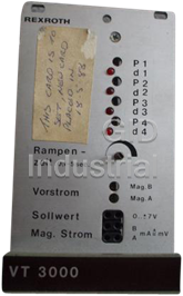
Rexroth VT 3000-3X Analog Amplifier Card | for Proportional Directional Valves
Part Number
VT 3000-3X
Price
Request Quote
Manufacturer
BOSCH REXROTH
Lead Time
Request Quote
Category
Analog Amplifier Card
Features
- Differential input
- Four command value call-ups with LED display
- Four command values adjustable with potentiometers
- Polarity protection for the voltage supply
- Ramp generator
- Step function generator
- Suitable for the control of pilot operated proportional directional valves (type .WRZ, up to series 6X) and direct operated proportional pressure valves (type DBEP6 and 3DREP6, each series 1X) with
- Two pulsed current output stages
Datasheet

Extracted Text
Electric Drives Linear Motion and and Controls Hydraulics Assembly Technologies Pneumatics Service RA 29935/07.03 1/8 Analog amplifi er Replaces: 05.00 Model VT 3000 Series 3X Table of contents Features Contents Page – Suitable for the control of pilot operated proportional directio- nal valves (type .WRZ, up to series 6X) and direct operated Features 1 pro por tio nal pressure valves (type DBEP6 and 3DREP6, each Ordering code 1 series 1X) without electrical position feedback Functional description 2 – Four command values adjustable with potentiometers Block circuit diagram / pin assignment 3 – Four command value call-ups with LED display Technical data 4 – Differential input Output curve 5 – Step function generator Indicator / adjustment elements 5 – Ramp generator Unit dimensions 6 – Two pulsed current output stages Engineering / maintenance notes / – Polarity protection for the voltage supply supplementary information 6 Card holder: Note: – Type VT 3002-2X/32, see RE 29 928 Single card holder without power pack When supplied the amplifi ers have a ramp time of 5 s (setting of the ramp time of 1 s see page 5). Power supply unit: – Type VT-NE30-1X, see RE 29 929 Compact power pack 115/230 VAC → 24 VDC, 70 VA Ordering code VT 3000 – 3X / * Amplifi er for prop. directional valves (type .WRZ, up to series 6X) Further details in plain text and prop. pressure valves (type DBEP6 and 3DREP6, each series 1X) Series 30 to 39 (30 to 39: unchanged technical data and pin assignment) = 3X 2/8 Bosch Rexroth Corp. | Industrial Hydraulics VT -3000 | RA 29935/07.03 Functional Description With the command value inputs 1 to 4 command values can be External time potentiometer and ramp "Off" called up [1] by operating the corresponding relays (K1 to K4). The command value voltage is either given directly through the controlled voltages ± 9 V of the power supply [10] or via an 14a external command value potentiometer. For this inputs ± 9 V 500 K Ramp "controllable" 1) 14c = ± 100 % is valid. If these four command value inputs are min. time at 0 Ω directly connected to the controlled voltages ± 9 V four different 26a max. time at 500 Ω command values can be set at the potentiometers "R1" to "R4". When using external command value potentiometers at these 14a inputs the internal potentiometers also function as weakeners or 14c Ramp "on/off" limiters when these are not set to maximum. External command value potentiometer Note: When using an external time potentiometer the internal 10c (10a, 8a, 12a) Inputs potentiometer for the ramp time must be set at maximum. 20c + 9 V The maximum ramp time decreases because the resistance 5 K Control of the external potentiometer is connected parallel to the 20a M0 solenoid "B" internal potentiometer! 26a By switching the relay K5 or through an external bridge the ramp time is set to its minimum value (approx. 30 ms). 10c (10a, 8a, 12a) Inputs The output signal of the ramp generator [4] runs parallel to the 26c – 9 V summator [6] and the step function generator [5]. The step 5 K Control function generator produces a polarity-dependent constant step 20a M0 solenoid "A" signal with the command value voltages which is added to the 26a output signal of the ramp generator. This step function causes the rapid travelling across the overlapping area of the valve spool. 10c (10a, 8a, 12a) Inputs The output signal of the summator [6] is the command current value and is led to the two current output stages [7] and to the 20c + 9 V 5 K Control test point "w" on the front plate of the card. A voltage of 6 V at 26c – 9 V solenoid "A"+"B" the command value test point corresponds to a command value 26a of 100 %. A po si ti ve command value signal at the input of the amplifi er controls the output stage for solenoid "B", a negative Which command value is momentarily called up is indicated by command value signal the output stage for solenoid "A". If the the LEDs "H1" to "H4". If more than one command value is called command value signal is smaller than ± 1 % (step function still up simultaneously the input with the highest number has priority. ineffective) a pilot current of 20 mA fl ows through both so le no ids. Example: If command value 1 and command value 3 are activated The actual values of the currents through the two solenoids can simultaneously the command value 3 becomes effective. be measured separately at the test points "I " (solenoid "A") and A "I " (solenoid "B"). Here a current of 800 mA corresponds to a A further output of the card provides a supply voltage for the B voltage of 800 mV. command value call-ups which can be switched over from + 9 V 1) to – 9 V with the relay K6 . LED "H11" lights up when the system is powered up. All relays on the card are switched with 24 VDC (smoothed). LED "H12" ("Ready for operation") lights up to indicate trouble-free operation as long as: Additionally, the direct command value input 5 is available for the 1) – the internal power supply (± 9 V) is functioning properly input voltage 0 to ± 6 V. Valid is ± 6 V = ± 100 % . – there is no short-circuit in the solenoid lines The command value input 6 is a differential input (0 to ± 10 V). If In the event of a fault, both output stages are immediately the command value is presented by a separate electronics with deenergized and the signal "Ready for operation" is cancelled. a dif fe rent reference potential this input must be used. When Once the fault has been cleared, the amplifi er card is immediately switching on or off the command value it must be taken care operable and LED "H12" lights up again. that both signal lines are either separated from or connected to the input. 1) All command values are summated with the correct value and = Reference potential for the command values 1 to 5 is M0 sign before they are connected further[3]. (measuring zero) The added ramp generator [4] produces a ramp-like output signal [ ] = Allocation in block circuit diagram page 3 from the jump-like given input signal. The time constant can be set with the potentiometers "t1" to "t5". The ramp time given refers to a command value jump of 100 % and can be, according to the setting through the selection via jumpers (J5, J6), approximately 1 s or 5 s. If a command value jump smaller than 100 % is switched to the input of the ramp generator the ramp time shortens appropriately. RA 29935/07.03 | VT -3000 Industrial Hydraulics | Bosch Rexroth Corp. 3/8 Block circuit diagram / pin assignment Positive comm. value X1 X1 Current command value at "w" controls solenoid "B" 0 to + 6 V for solenoid "A" 14c Negative comm. value External 0 to – 6 V for solenoid "B" controls solenoid "A" 14a 8 ramp Current actual value I at "I " A A 12c Current actual value I at "I " B B Command value 5 ± 6 V Biasing current F 12a solenoid "A" Command value 4 ± 9 V w 8a 7 Command value 3 ± 9 V F 30a F I 7 10a A u t Command value 2 ± 9 V 24a 10c i Σ Command value 1 ± 9 V F F F F R2 R4 5 R1 R3 Solenoid „A" K5 3 4 6 F 1 I Σ B Σ K4.1 K3.1 J5, J6 K2.1 K1.1 2 22a 16a F Differential Command value 6 28c i 9 u H12 28a u 16c input u Σ Reference potential 7 Solenoid „B" 7 – Biasing current K6 2a Aux. voltage ± 9 V solenoid "B" 18a Comm. value + after ramp 10 20c 32a Measuring zero (M0) is + 9 V = 20a + U 32c F B raised by 9 V compared to M0 2,5 A T H11 26c Operating 0 V operating voltage! 2200 μF – 9 V voltage F 1 8c K1 H1 26a 0 V Call-up command value 1 F 4a K2 H2 Call-up command value 2 F 6a K3 H3 Call-up command value 3 F 6c K4 H4 Call-up command value 4 18c K5 Call-up "Ramp off" K6 4c Call-up "Switch-over aux. voltage" 1 Command values Relay call-up voltage (+ 24 V) 2 Differential input F = on front plate 3 6 Summator 4 Ramp generator 5 Step function generator 7 Current output stage H1 to H4 = LED-display for comm. value call-ups K1 to K6 = Call-up relais For explanation of jumpers (J5, J6) 8 Pulse generator H11 = "Power on" R1 to R4 = Command values and arrangement of indicator and 9 Monitorings H12 = "Ready for operation" t = Ramp time 10 Power supply adjustment elements, see page 5 4/8 Bosch Rexroth Corp. | Industrial Hydraulics VT -3000 | RA 29935/07.03 Technical Data (for application outside these parameters please consult us!) 1) Operating voltage U 24 VDC + 60 % – 5 % B Operating range: – Upper limit value u (t) 39 V B max – Lower limit value u (t) 22 V B min Power consumption P < 50 VA S Current consumption I < 1 A (with loading current) Fuse I 2,5 A T S Inputs: – Command values 1 to 4 U ± 9 V (reference potential is M0) e – Command value 5 U ± 6 V (reference potential is M0) e – Command value 6 (differential input) U 0 to ± 10 V; R = 100 kΩ e e Ramp time (setting range) t 30 ms to approx. 1 s or 5 s Outputs: – Output stage • Solenoid current/ resistance I 800 mA; R = 19,5 Ω max (20) • Biasing current I 20 mA ± 25 % V • Pulse frequency f 170 Hz ± 10 % – Regulated voltage U ± 9 V ± 1 %; ± 25 mA externally loadable – Measuring sockets • Current command value „w“ U ± 6 V; R = 5 kΩ i • Current actual value "I "; "I " U ; U 0 to 800 mV equivalent 0 to 800 mA A B A B Relay data: – Nominal voltage I operating voltage U B – Threshold voltage U 16,8 V – Return voltage U 2,4 V – Coil resistance R 2150 Ω Type of connection 32-pin terminal strip, DIN 41 612, form D Card dimensions Euro-card 100 x 160 mm, DIN 41 494 Front plate dimensions – Height 3 HE (128,4 mm) – Width soldering side 1 TE (5,08 mm) – Width component side 7 TE Permissible operating temperature range ϑ 0 to 50 °C Storage temperature range ϑ – 25 to 85 °C Weight m 0,13 kg 1) To guarantee the max. solenoid current for the solenoid (19,5Ω) in the complete solenoid temperature range the operating voltage must be at least 28 VDC! Note: For details regarding environmental simulation test in the fi eld of EMC (electromagnetic compatibility), climate and mechanical stress, see RE 30 304-U (declaration on environmental compatibility). RA 29935/07.03 | VT -3000 Industrial Hydraulics | Bosch Rexroth Corp. 5/8 Output curve Solenoid "A" Solenoid "B" 800 600 400 200 20 –100% –50% –1% +1% +50% +100% ← Command value in % → Indicator / Adjustment elements Max. ramp time Biasing current approx.1 s or 5 s solenoid "A" H11 J6 H12 R1 H1 J5 R2 H2 R3 H3 R4 F1 H4 2,5 A T t w I B I A VT 3000 Biasing current solenoid "B" LED lamps: H1 Call-up command value 1 H2 Call-up command value 2 H3 Call-up command value 3 H4 Call-up command value 4 Meaning of the jumpers on the card for the settings H11 Operating voltage "Power on" (yellow) (Label on the back of the front plate) H12 Indication "Ready for operation" (green) Potentiometer: ramp time Jx = bridge jumper plugged in R1 Command value 1 R2 Command value 2 5 s J5 J6 Jx = open jumper open R3 Command value 3 1 s J6 = delivery state J5 delivery condition R4 Command value 4 t Ramp time ramp time Measuring sockets: w Command value solenoid current I Actual current value solenoid "A" A Note: I Actual current value solenoid "B" B The loss of unused jumpers can be avoided by plugging these jumpers into only one pin. Output current in mA → X1 6/8 Bosch Rexroth Corp. | Industrial Hydraulics VT -3000 | RA 29935/07.03 Unit dimensions – dimensions in millimeters H11 H12 R1 H1 R2 H2 R3 H3 R4 H4 t w I B I A VT 3000 8TE(40,3) 2 7 165 186 Engineering / maintenance notes / supplementary information – The amplifi er card may only be plugged in or unpluged when switched off! – Do not use plugs with free wheel diodes or LED displays when connecting the solenoids! – Only carry out measurements on the cards with instruments R > 100 kΩ! i – Measuring zero (M0) is raised by + 9 V compared to 0 V operating voltage and is not potentially separated , i.e. – 9 V controlled voltage is equivalent to 0V operating voltage . Therefore do not connect measuring zero (M0) to 0 V operating voltage! – When switching command values use relays with gold contacts (small voltages , small currents)! – When switching card relays only use contacts with a loadability of approx. 40 V, 50 mA! When controlling externally the control voltage may have a maximum residual ripple of 10 %! – Always screen command value lines; connect screen to 0 V operating voltage on the card side, other side remains open (danger of earth loops)! Recommendation: Also screen solenoid lines! 2 Use cable type LiYCY 1,5 mm for solenoid lines of up to 50 m in length. For longer lengths please consult us! – Minimum distance to arial lines, radio sources and radar equipment must be at least 1m! – Do not lay solenoid and signal lines near power lines! – Because of the loading current of the smoothing capacitor on the card pilot fuses must be slow! – Warning: When using the differential input both inputs must always be switched on or off simultaneously! 3HE (128,4) 100 89 15 7 RA 29935/07.03 | VT -3000 Industrial Hydraulics | Bosch Rexroth Corp. 7/8 Notes 8/8 Bosch Rexroth Corp. | Industrial Hydraulics VT -3000 | RA 29935/07.03 © This document, as well as the data, specifi cations and other Bosch Rexroth Corp. information set forth in it, are the exclusive property of Bosch Rexroth Industrial Hydraulics Corporation. Without their consent it may not be reproduced or given to 2315 City Line Road third parties. Bethlehem, PA 18017-2131 The data specifi ed above only serve to describe the product. No USA statements concerning a certain condition or suitability for a certain Telephone (610) 694-8300 application can be derived from our information. The information given Facsimile (610) 694-8467 does not release the user from the obligation of own judgment and www.boschrexroth-us.com verifi cation. It must be remembered that our products are subject to a natural process of wear and aging.
Frequently asked questions
How does Industrial Trading differ from its competitors?

Is there a warranty for the VT 3000-3X?
Which carrier will Industrial Trading use to ship my parts?
Can I buy parts from Industrial Trading if I am outside the USA?
Which payment methods does Industrial Trading accept?


What they say about us
FANTASTIC RESOURCE
One of our top priorities is maintaining our business with precision, and we are constantly looking for affiliates that can help us achieve our goal. With the aid of GID Industrial, our obsolete product management has never been more efficient. They have been a great resource to our company, and have quickly become a go-to supplier on our list!
Bucher Emhart Glass
EXCELLENT SERVICE
With our strict fundamentals and high expectations, we were surprised when we came across GID Industrial and their competitive pricing. When we approached them with our issue, they were incredibly confident in being able to provide us with a seamless solution at the best price for us. GID Industrial quickly understood our needs and provided us with excellent service, as well as fully tested product to ensure what we received would be the right fit for our company.
Fuji
HARD TO FIND A BETTER PROVIDER
Our company provides services to aid in the manufacture of technological products, such as semiconductors and flat panel displays, and often searching for distributors of obsolete product we require can waste time and money. Finding GID Industrial proved to be a great asset to our company, with cost effective solutions and superior knowledge on all of their materials, it’d be hard to find a better provider of obsolete or hard to find products.
Applied Materials
CONSISTENTLY DELIVERS QUALITY SOLUTIONS
Over the years, the equipment used in our company becomes discontinued, but they’re still of great use to us and our customers. Once these products are no longer available through the manufacturer, finding a reliable, quick supplier is a necessity, and luckily for us, GID Industrial has provided the most trustworthy, quality solutions to our obsolete component needs.
Nidec Vamco
TERRIFIC RESOURCE
This company has been a terrific help to us (I work for Trican Well Service) in sourcing the Micron Ram Memory we needed for our Siemens computers. Great service! And great pricing! I know when the product is shipping and when it will arrive, all the way through the ordering process.
Trican Well Service
GO TO SOURCE
When I can't find an obsolete part, I first call GID and they'll come up with my parts every time. Great customer service and follow up as well. Scott emails me from time to time to touch base and see if we're having trouble finding something.....which is often with our 25 yr old equipment.
ConAgra Foods