

 Manufacturers
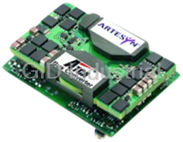
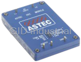
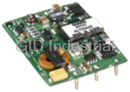
ASTEC ATC210-48D12-03J
Description
Astec ATC210-48D12-03J 210W ATCA bus converters
Part Number
ATC210-48D12-03J
Price
Request Quote
Manufacturer
ASTEC
Lead Time
Request Quote
Category
Converters
Specifications
+12V1 VDC
@17.5A
+3.3 VDC
@1.8A
Input (PS)
36 V to 75 V
Operating Temperature
-25 to 85C
Performance Characteristics
Dual
Total Max Current
17.5 A
Volume
2.320" x 1.810" x 0.830"
Features
- EMI Filtering
- Fully integrated input power entry module and intermediate bus converter solution for high density ATCA applcations
- Hot swap capability with inrush protection
- I2C serial bus interface for monitoring and reporting
- Independent 50V clamp output for charging extrenal hold up capacitors
- Oring for A/B Dual 48Vdc power feeds
Datasheet

Extracted Text
ATC210 Dual Series | 210 W DC-DC Intermediate Bus Converters ATC210 Dual-Input Bus Converter Integrated Power Conversion and Power Management Solution Footprint optimized for high-density ATCA applications Accepts inputs from both -48 V “A” and “B” feeds Power management functions include ORing, inrush control and transient protection 210 W on 12 V Intermediate Bus 6 W on 3.3 V Management Power Bus 2 I C serial bus interface for monitoring and reporting 2 Programmable alarm thresholds via I C Bus Hardware alarms via opto-isolators for loss of A or B feeds Comprehensive protection circuitry - current, voltage and temperature RoHS compliant The dual input ATC210 bus converter Critical alarms, such as loss of A or B provides AdvancedTCA (ATCA/PICMG3.0) feeds, are hardware-implemented. Other 2 board designers a compact and rugged alarms are implemented over an I C serial solution for generating intermediate bus bus which is enhanced with an interrupt voltages in a footprint-optimized package. pin. The ATC210 is more than a power The solution is provided in a 2.3 x 1.8 inch converter. It also provides power interface (59mm x 46mm) footprint and provides an and power management functionality. The optimized solution for space-constrained power interface functions include ORing, systems that employ distributed power filtering and inrush control, while power architectures. management functionality is facilitated by 2 both I C serial bus and direct high-speed interfaces. [ 2 YEAR WARRANTY ] 1 File Name: atc210.pdf Rev: 16 Aug 2006 SXA10 Series | 15W DC-DC ATC210 Dual Series | 210 W DC-DC Intermediate Bus Converters Stresses in excess of the maximum ratings can cause permanent damage to the device. Operation of the device is not implied at these or any other conditions in excess of those given in the specification. Exposure to absolute maximum ratings can adversely affect device reliability. Absolute Maximum Ratings Characteristic Symbol Min Typ Max Units Notes and Conditions Input voltage - continuous V 0 -75 Vdc V (+) - V (-) in (cont) in in Input voltage - peak V -100 Vdc Transients of 1 ms or in (peak) less duration Operating temperature T -25 85 ºC Refer to thermal specification op section for derating guidelines Storage temperature T -40 125 ºC storage Output power P 0 210 W Main output load current must out (max) not exceed 17.5 A. Combined power not to exceed 210 Watts All specifications are typical at nominal input Vin = 48 V, full load under any resistive load combination at 25 ˚C unless otherwise stated. Input Characteristics Characteristic Symbol Min Typ Max Units Notes and Conditions Input voltage - operating V -36 -72 Vdc Management power available in (oper) down to lower UVLO threshold Input current - quiescent l 10 mAdc Outside working voltage range in(off) for 2 s or more Input Current - operating I 0.142 A @ 55.2 Vin in (cont)_48 V no load on 12 Vout and 3.3 Vout I 0.137 A @ 69.0 Vin in (cont)_60 V Typical float voltage for 48 V and 60 V systems Input capacitance requirement C 82 μF See Application Note 205 i/p (external) Inrush current, maximum l 8.8 10.30 A Compliant with PICMG inrush amplitude 3.0 sec 4.1.4.1 for boards Inrush current, duration T 2.00 ms Compliant with PICMG inrush 3.0 sec 4.1.4.1 for boards Input fuse 10/12 A In –48_A,B / RTN A,B lines* *See Application Note 205 (Section 5.2) for manufacturer and part number. Input Characteristics - Overload and Short Circuit Protection Characteristic Symbol Min Typ Max Units Notes and Conditions Primary overload current I 7.7 8.8 10.3 A Maximum current draw during pri_OL Primary overload duration T 2.8 3.0 ms overload event pri_OL Short circuit protection I 1.8 5.7 A Maximum at 36 Volts Vin S/C_switch on across inrush capacitance (pin T 2.0 2.4 2.6 ms S/C_switch on 11 wrt pin 10). Also includes I 85 A Worse case at 72 Volts Vin S/C_operational the main power line from post T 12 μ μs S/C_operational inrush circuit up to and including the IBC input For all above overload and short circuit conditions, the unit shuts off safely. The unit can be restarted, providing the fault condition is no longer present. 2 File Name: atc210.pdf Rev: 16 Aug 2006 ATC210 Dual Series | 210 W DC-DC Intermediate Bus Converters Turn On/Off Characteristic Symbol Min Typ Max Units Notes and Conditions Input voltage - turn-on V -36 Vdc in (on) Input voltage - turn-off V -32 Vdc in (uvlo) Input voltage - turn-on V -72 Vdc in (on) Input voltage - turn-off V -77.5 Vdc in (ovlo) Rise time T 1.1 ms 0 to 90%, full load, max output rise_3.3 V capacitance. 3.3 V comes up first T 20 ms 0 to 90%, full load, max output rise_12 V capacitance. Signal Electrical Interface Characteristic - Signal Name Symbol Min Typ Max Units Notes and Conditions Remote ON/OFF Isolated floating opto coupler (Input only) pins 14 and 13 input. Can use 3.3 V output (secondary) or directly use enable A or B (primary) to turn on main 12 V output Input current I 1.6 5.0 mA Current flowing (into pin 14, out ih of pin 13) to turn on 12 V output Acceptable high level I 10 μA Acceptable leakage current (into ih (leakage) pin 14, out of pin 13) Low level input voltage V 3.0 V Converter is guaranteed on il when r/c voltage (pin 14 wrt to pin 13) is equal to or greater than Vil (min) Opto coupler voltage drop V 1.5 V Maximum photodiode voltage drop d(on) Internal resistance R 1.0 kΩ Series resistance between pin 14 int and pin 13 Isolation Basic Isolation of signal from primary and from secondary circuits according to EN60950 and UL60950 A_OK# and B_OK# Two open collector outputs, (Output only) pins 16 and 17 used to monitor the status of -48 V_A and -48 V_B buses respectively. Signal is active low, when buses are ‘OK’ Input Voltage (IBC) 35.0 Minimum voltage required at the input to IBC for A_OK# and B_OK# to be okay Input current (sink) I 0.3 0.8 3.4 mA Sink current capability of each pin ol Maximum allowable I 10 μA Maximum leakage current in ol_leakage leakage current open collector transistor when pin is pulled to 3.3 V Isolation Basic Isolation of signal pins from primary circuits according to EN60950 and UL60950 3.3 V Trim (Input only) Allows the 3.3 V to be trimmed pin 27/28 up and down Controlled output voltage range V 3.48 3.52 V Connect trim pin to output return o trim up V 3.13 3.16 V to trim high, and to 3.3 Vout to o trim down trim low. See Application Note 205 Programme/V select law R 8.06 kΩ V/mA, current from pin control increases output voltage See Application Note 205 for further details 3 www.artesyn.com File Name: atc210.pdf Rev: 16 Aug 2006 SXA10 Series | 15W DC-DC ATC210 Dual Series | 210 W DC-DC Intermediate Bus Converters Signal Electrical Interface Contd. Characteristic - Signal Name Symbol Min Typ Max Units Notes and Conditions Interrupt (output only) pin 18 Output, which goes active low when any of the measured parameters goes outside its limits. See Application Note 205 for further detail High level output voltage V 2.90 3.10 3.30 V Interrupt is not active oh Low level output voltage V 0.1 V Interrupt is active ol High level output current I 5.0 mA Output source current oh Low level sink current I 5.0 mA Output sink current ol 2 I C Bus (input and output) SDA and SCL referenced to pins 20 and 22 secondary side 3.3 V return Low level sink current I 5.0 mA provide the communication path ol with the ‘host’ system. See Application Note 205 for further details 2 Clock frequency I C 100 kHz This value is fixed freq 2 Address A0, A1, A2 Forms part of the I C binary pins 21, 19 and 17 (input only) address. These are hardwired to logic ‘1’ via 10 k pull-ups, but can be configured to logic ‘0’ by connecting to 3.3 V output return via zero Ω link(s). See Application Note 205 for further details Enable A & B (input only) These two inputs effectively connect to their respective returns once the Zone1 connector mates with the Zone1 socket on the backplane. Both Enables must mate to start up the unit Holdup Characteristics Characteristic Symbol Min Typ Max Units Notes and Conditions Hold up capacitance C Chold_min 8,000 μF Chold_min depends on load and holdup requirement hold up requirement on customer system. See Application Note 205 Clamp voltage V 41.0 41.5 V Voltage on hold up capacitors cl (pin 12 wrt pin 9) when input is 43 V and 210 W load Clamp voltage OVP V 48.0 V If the clamp voltage exceeds cl_ovp V , the unit trips. Reset is cl_ovp achieved by cycling the input power 4 File Name: atc210.pdf Rev: 16 Aug 2006 ATC210 Dual Series | 210 W DC-DC Intermediate Bus Converters Common Protection/Control Characteristic Symbol Min Typ Max Units Notes and Conditions Overtemperature protection T 120 125 130 ºC The IBC shuts down, resulting in op (IBC) both shut down of 3.3 V and 12 V. Once the substrate temperature has decreased by 5 ºC, the IBC turns back on enabling both voltages Overtemperature protection Temperature sensors are on (main unit) primary and secondary side. Primary side threshold T 107 ºC Once the thresholds have been pri Secondary side threshold T 102 ºC exceeded, the 12 V output is sec Primary side hysterisis T 20 ºC disabled, but the 3.3 V remains. pri_hys Secondary side hysterisis T 10 ºC The 12 V output can only be sec_hys enabled by cycling power or 2 through the I C interface provided that the temperature has decreased below its hysterisis level. Adjustable primary and secondary thresholds are also provided and can be set lower than the fixed thresholds. See Application Note 205. Reliability and Service Life Characteristic Symbol Min Typ Max Units Notes and Conditions Mean time between failure MTBF 2,008,000 Hours Telcordia SR-332 V = V ; I = I in in (nom) out out ; ambient 25 ºC; (max) ground benign environment Other Specifications Characteristic Symbol Min Typ Max Units Notes and Conditions Switching frequency F 400 kHz As determined by IBC sw Weight 80 g Environmental Specifications Characteristic Symbol Min Typ Max Units Notes and Conditions Thermal Performance T -25 85 ºC See derating curves (Figures 1,2) op 5 www.artesyn.com File Name: atc210.pdf Rev: 16 Aug 2006 SXA10 Series | 15W DC-DC ATC210 Dual Series | 210 W DC-DC Intermediate Bus Converters EMC Electromagnetic Compatibility Phenomenon Port Standard Test level Criteria Notes and conditions Immunity: Radiated immunity EN61000-4-3 ESD Enclosure EN61000-4-2 6 kV contact As per ETS 300 386-1 table 5 8 kV air Emissions: Conducted emission -48 V A or B bus EN55022 A/B Conducted See Application Note 205 for guidelines and returns on how to meet the required EMI standard Referenced ETSI standards: ETS 300 386-1 table 5 (1997): Public telecommunication network equipment, EMC requirements ETS 300 132-2 (1996): Power supply interface at the input to telecommunication equipment: Part 2 operated by direct current (dc) ETR 283 (1997): Transient voltages at interface A on telecommunication direct current (dc) power distributions PICMG® 3.0 rev 2.0 : AdvancedTCA™ Base Specification Safety Agency Approvals Characteristic Notes and Conditions UL/cUL60950-1 E174104 TÜV Product Services EN60950-1 B051138572060 CB certficate and report to DE3-53905 IEC60950-1 Material Ratings Characteristic Notes and Conditions Flammability rating UL94V-0 Model Numbers Model Input Output Output Current Typical Max. Load Note Number Voltage Voltage (Max.) Efficiency Regulation ATC210-48D12-03J -36 to -72 Vdc 12 V 17.5 A 89% @ full load ±5% Total output power = 210 W 3.3 V 1.8 A ±3% Management power RoHS Compliance Ordering Information The ‘J’ at the end of the part number indicates that the part is Pb-free (RoHS 6/6 compliant). TSE RoHS 5/6 (non Pb-free) compliant versions may be available on special request, please contact your local sales representative for details. 6 File Name: atc210.pdf Rev: 16 Aug 2006 ATC210 Dual Series | 210 W DC-DC Intermediate Bus Converters Electrical Characteristics - O/P Characteristic Symbol Min Typ Max Units Notes and Conditions Main Output - 12V Nominal set-point voltage V 12.2 Vdc V = V o (nom) in in (nom) Total regulation band V 11.4 12.6 V For all line, static load and o temperature variations Output current continuous I 0 17.5 Adc out Output current limit I 21.6 22.5 23.4 Adc During a short-circuit or when ocp current limit of 12 V is exceeded, 12 V latches off, 3.3 V remains on. The 12 V can only be enabled by cycling power, or 2 via the I C interface, providing the fault condition has cleared. See Application Note 205 Overvoltage protection for IBC V 13.4 14.6 15.9 OVP response time is 50 μs (typ.) ovp Output voltage - noise, pk-pk V 0 50 100 mV p-p Measurement bandwidth 20 MHz pk-pk V 0 20 50 mVrms Measurement bandwidth 20 MHz rms Output voltage during hold up V 11 Vdc Lowest value of V @ I o (hold) o out max. event with input removed for hold up duration with recommended hold up capacitance Output capacitance C 1000 6000 μF Capacitance should be low ESR o/p type. See Application Note 205 Electrical Characteristics - O/P Characteristic Symbol Min Typ Max Units Notes and Conditions Management Power - 3.3V Nominal set-point voltage V 3.32 Vdc V = V o (nom) in in(nom) Total regulation band V 3.20 3.40 V For all line, static load and o temperature variations Output current continuous I 1.81 Adc out Output current limit I 2.7 Adc Current measured at out_95% approximately 95% of output voltage Output current at short circuit I 3.7 4.0 Adc Short circuit of less than 10 mΩ s/c Output self recovers upon removal of the short circuit Output voltage monitor limits V 2.94 3.00 Vdc If the 3.3 V goes outside these uvp V 3.60 3.67 Vdc limits, the 12 V output is ovp disabled. The 12 V output is enabled again by cycling input 2 power, or by resetting via I C Output voltage - noise, pk-pk V 0 25 50 mV p-p Measurement bandwidth 20 MHz pk-pk V 0 8 22 mV rms Measurement bandwidth 20 MHz rms Output voltage during hold up V 3.25 Vdc Lowest value of V @ I o (hold) o out max event with input removed for hold up duration with recommended hold up capacitance Output capacitance C 100 1000 μF Capacitance should be low ESR o/p type . See Application Note 205 7 www.artesyn.com File Name: atc210.pdf Rev: 16 Aug 2006 SXA10 Series | 15W DC-DC ATC210 Dual Series | 210 W DC-DC Intermediate Bus Converters Efficiency Characteristic Symbol Min Typ Max Units Notes and Conditions Efficiency η 86 89 % full load, low to high line (12 V and 3.3 V = 210 W) Isolation Characteristics Characteristic Symbol Min Typ Max Units Notes and Conditions Input to output insulation system Basic Input to output test voltage 2,250 Vdc Test duration 1s Input to output capacitance 2,000 pF Input to output resistance 100 MΩ Measured with 500 Vdc A_OK# and B_OK# Basic Isolation from primary circuit ON/OFF+ and ON/OFF- Basic Isolation from both primary and secondary circuits 8 File Name: atc210.pdf Rev: 16 Aug 2006 ATC210 Dual Series | 210 W DC-DC Intermediate Bus Converters 2 2 2 I C Serial bus Interface - This page is a summary of the I C features set for further detail refer to App 206 I C Serial Bus Interface 2 I C Addressing and Access Value Registers, Address 20 h to 28 h Type Parameter Name Description Scaling Factor Address Voltage (Pri) -48 V Voltage between HU- and HU+IN 0.2915 V/bit 20 h Current (Pri) -48 V Current after input OR-ing 0.0273 A/bit 21 h Voltage (Pri) -48 V_A Voltage between –48V A and RTN A 0.2817 V/bit 22 h Voltage (Pri) -48 V_B Voltage between –48V A and RTN A 0.2817 V/bit 23 h Voltage (Sec) 3.3 V Management power voltage 0.0170 V/bit 24 h Voltage (Sec) 12 V Intermediate bus voltage 0.0598 V/bit 25 h Current (Sec) 12 V Current in intermediate bus 0.1082 A/Bit 26 h Temperature (Sec) Temp Secondary side temperature 0.5 ºC/bit-10 ºC 27 h Temperature (Pri) Temp Primary side temperature 0.5 ºC/bit-10 ºC 28 h The temperature parameter is scaled at 0.5 ºC/bit with an offset of -10 ºC for a range of -10 ºC (00 h) to 117 ºC (FFh). Serial Bus Interface General Description Characteristic Notes and Conditions 2 Bus type I C Clock frequency 100 kHz Supply Voltage (Note 1) 3.3 V Inventory Data Parameter Name Address Field Size Firmware revision (primary) 40 h-47 h 8 Firmware revision (secondary) 48 h-4F h 8 Firmware P/N (primary) 50 h-5F h 16 Firmware P/V (secondary) 60 h-6F h 16 ATC210 P/N (Artesyn format) 70 h-87 h 24 ATC210 Revision 88 h-8F h 8 ATC210 Serial No. 90 h-97 h 8 ATC210 Date Code 98 h-9F h 8 ATC210 Vendor (Artesyn) A0 h-A7 h 8 9 www.artesyn.com File Name: atc210.pdf Rev: 16 Aug 2006 SXA10 Series | 15W DC-DC ATC210 Dual Series | 210 W DC-DC Intermediate Bus Converters 300 300 250 250 200 200 400 LFM 400 LFM 300 LFM 300 LFM 150 150 200 LFM 200 LFM 100 LFM 100 LFM 100 100 50 50 0 0 5 15 25 35 45 55 65 75 85 5 15 25 35 45 55 65 75 85 AMBIENT TEMPERATURE (ºC) AMBIENT TEMPERATURE (ºC) Figure 1: Derating Curve with Forced Air Figure 2: Derating Curve with Forced Air -39 V to -60 V input -36 V to -72 V input 100 91.00 90 90.50 80 39.5 V 90.00 Full Load 48.0 V 70 72.0 V 89.50 60 89.00 50 35 45 55 65 75 2 4 6 8 10 12 14 16 18 INPUT VOLTAGE (V) OUTPUT CURRENT (A) Figure 3: Efficiency vs. Line (Full Load) Figure 4: Efficiency vs. Load 12 Vout 12 Vout 48 Vin 48 Vin 3.3 Vout 3.3 Vout Figure 5: Turn-On Characteristic (48 Vin) Figure 6: Turn-Off Characteristic Channel 1: 12 Vout; Channel 2: 3.3 Vout; Channel 4: 48 Vin Full Resistive Load (Input Power Removed) Channel 1: 12 Vout; Channel 2: 3.3 Vout; Channel 4: 48 Vin 10 File Name: atc210.pdf Rev: 16 Aug 2006 OUTPUT POWER (W) EFFICIENCY (%) OUTPUT POWER (W) EFFICIENCY (%) ATC210 Dual Series | 210 W DC-DC Intermediate Bus Converters Inrush Current 12 Vout V Inrush Capacitor 82 μF 3.3 Vout Figure 7: Typical Output Ripple and Noise Measurement Figure 8: Inrush Current (39.5 V) Channel 3: Inrush Current; Channel 1: 12 Vout; Channel 2: 3.3 Vout Channel 4: Voltage Across Inrush Capacitor V Inrush I_12 Vout Capacitor 82 μF R/C Turn-on 12 Vout signal Inrush Current ‘Starting off’ point gets lower as input voltage increases (Initial step is to charge up capacitance) Figure 10: Remote Control Turning-on Characteristic. Figure 9: Inrush Current (72 V) Vin = 48 Volts, Turning-on into Full Load for 12 Vout and 3.3 Vout Channel 3: Inrush Current; Channel 4: Voltage Across Inrush Capacitor 12 Vout 12 Vout I_12 Vout R/C Turn-off signal 50-75% 75-50% transient transient Figure 12: Typical Transient Response 75-50% and 50-75% Figure 11: Remote Control Turning-off Characteristic. Step Load Change (1 A/μs), Vin = 48 Volts, Turning-off into Full Load for 12 Vout and 3.3 Vout Channel 1: 12 Vout; Channel 3: Iout (12 Vout). Cout = 6000 μ μF 11 www.artesyn.com File Name: atc210.pdf Rev: 16 Aug 2006 SXA10 Series | 15W DC-DC ATC210 Dual Series | 210 W DC-DC Intermediate Bus Converters 12 Vout (maintained during hold-up period) current Hold-up voltage limit point available to IBC 12 Vout Iprimary (off for 5 ms) 3.3 Vout I_12 Vout 3.3 Vout Figure 14: Hold-up Characteristic Figure 13: 12 Vout Current Limit Vin = 43 Volts, 12 Vout @ 17.5 Amps, 3.3 Vout @ 1.81 Amps Channel 1: 12 Vout; Channel 2: 3.3 Vout Channel 3: Iout (12 Vout) 12 File Name: atc210.pdf Rev: 16 Aug 2006 ATC210 Dual Series | 210 W DC-DC Intermediate Bus Converters 1 30 2 3 Recommended Drill Holes: 4 Pins 1 to 14 1.3 mm 5 29 TOP VIEW Pins 15 to 28 1.1 mm 6 Pins 29 and 30 1.9 mm 28 27 7 26 25 8 24 23 21 22 20 19 9 18 17 16 15 SIDE VIEW 10 11 12 13 14 2.32 (59.00) 1.65 (41.91) 1.55 (39.37) 1.65 (41.91) 1.45 (36.83) 1.50 (38.1) 1.35 (34.29) 1.20 (30.48) 1.25 (31.75) 1.05 (26.67) 1.15 (29.21) 0.90 (22.86) 1.05 (26.67) 0.75 (19.05) 0.75 (19.05) 0.6 (15.24) 0.45 (11.43) 0.30 (7.62) 0.15 (3.81) 0.15 (3.81) 0.00 BOTTOM VIEW Dimensions in Inches (mm) Tolerances (unless otherwise specified) x.xx ±0.02 (x.x ±0.5) x.xxx ±0.010 (x.xx ±0.25) Pin Functionality Pin Functionality Continued Pin Number / Pin Name Pin Size Pin Number / Pin Name Pin Size 1 -48V A 1.02 mm 16 A_OK# 0.64 mm Sq 2 -48V B 1.02 mm 17 A2 0.64 mm Sq 3 Reserved See Note 2 18 INTRPT 0.64 mm Sq 4 Reserved See Note 2 19 A1 0.64 mm Sq 5 RTN A 1.02 mm 20 SCL 0.64 mm Sq 6 RTN B 1.02 mm 21 A0 0.64 mm Sq 7 ENA 1.02 mm 22 SDA 0.64 mm Sq 8 ENB 1.02 mm 23 3V3 RTN 0.64 mm Sq 9 C_CL- 1.02 mm 24 3V3 RTN 0.64 mm Sq 10 HU- 1.02 mm 25 3V3 OUT 0.64 mm Sq 11 HU+OUT 1.02 mm 26 3V3 OUT 0.64 mm Sq 12 HU+IN 1.02 mm 27 3V3 TRIM 0.64 mm Sq 13 ON/OFF- 1.02 mm 28 3V3 TRIM 0.64 mm Sq 14 ON/OFF+ 1.02 mm 29 12V RTN 1.58 mm 15 B_OK# 0.64 mm Sq 30 12V OUT 1.58 mm Figure 15 - Mechanical Drawing and Assignment Table (Pin Size is Diameter unless Otherwise Stated) 13 www.artesyn.com File Name: atc210.pdf Rev: 16 Aug 2006 1.81 (46.00) 0.00 0.31 (7.91) 0.46 (11.72) 0.61 (15.53) 0.91 (23.15) 1.06 (26.96) 1.91 (48.55) 1.01 (25.58) 2.01 (51.09) 2.01 (51.09) 0.83 (21.08) 0.75 (19.05) ATC210 Dual Series | 210 W DC-DC Intermediate Bus Converters Pin Functionality Pin Number / Pin Name Function Note 1 -48V A Power input from ‘A’ bus Connects to ATCA Zone 1 connector pin 33 via external 10 A fuse 2 -48V B Power input from ‘B’ bus Connects to ATCA Zone 1 connector pin 34 via external 10 A fuse 3 Reserved For future use 4 Reserved For future use 5 RTN A Power return from ‘A’ bus Connects to ATCA Zone 1 connector pin 28 via external 12 A fuse 6 RTN B Power return from ‘B’ bus Connects to ATCA Zone 1 connector pin 29 via external 12 A fuse 7 ENA When connected to RTN A, turns ON Connects to ATCA Zone 1 connector pin 32 via external isolated open collector ‘A enabled’ device 1 A fuse. Used to signal to management system correct (See Note 3) board insertion and presence of ‘A’ bus 8 ENB When connected to RTN B, turns ON Connects to ATCA Zone 1 connector pin 27 via external isolated open collector ‘B enabled’ device 1 A fuse. Used to signal to management system correct (See Note 3) board insertion and presence of ‘B’ bus 9 C_CL- Connection to module of auxilliary Utilises greater capacitance in a given can size of lower capacitor hold up array -ve voltage capacitors. Clamped to –50 V wrt HU+OUT 10 HU- Connection to module of hold up capacitor array -ve 11 HU+OUT Connection from on board filter and May also connect to input of boost module to reduce management circuits to hold up hold up storage area capacitor array +ve 12 HU+IN Connection to main power converter from May also connect to output of boost module to reduce hold hold up capacitor array +ve up storage area 13 ON/OFF- Current from pin to turn main output ON Fully floating remote ON/OFF signal, may be used with management system or ATCA ENABLE_A/B via R-D network 14 ON/OFF+ Current into pin to turn main output ON Fully floating remote ON/OFF signal, may be used with management system or ATCA ENABLE_A/B via R-D network 15 B_OK# Open collector signal, monitors status of Low when “OK” “B” feed 16 A_OK# Open collector signal, monitors status of Low when “OK” “B” feed 2 17 A2 I C lines, address strapping 2 18 INTRPT Interrupt Alarm I C Register out of limits, LM80 pin ‘INT#’ direct connection 2 19 A1 I C lines, address strapping 2 20 SCL Clock I C lines, clock line input 2 21 A0 I C lines, address strapping 2 22 SDA Data I C lines, serial data 2 23, 24 3V3 RTN Management power return and I C Also return for ‘A _OK#’ and ’B_OK#’ signals. Externally connected to ATCA Zone 1 connector pin 26 25, 26 3V3 OUT 3V3, 6 W management power 27, 28 3V3 TRIM Trim pin for management power 29 12V RTN 12 V return Externally connected to ATCA Zone 1 connector pin 26 30 12V OUT 12 V power Pin-Out Table 14 File Name: atc210.pdf Rev: 16 Aug 2006 ATC210 Dual Series | 210 W DC-DC Intermediate Bus Converters Note 1 2 The reference return for the I C bus is on the secondary (SELV) side of the converter (i.e. 3V3_RTN) Note 2 Pins reserved for future use Note 3 Both ENables (ENA/ENB) have to be connected to their respective RTNS to enable the internal power management IC. CAUTION: Hazardous internal voltages and high temperatures. Ensure that unit is accessible only to trained personnel. The user must provide the recommended fusing in order to comply with safety approvals. 15 www.artesyn.com File Name: atc210.pdf Rev: 16 Aug 2006 SXA10 Series | 15W DC-DC ATC210 Dual Series | 210 W DC-DC Intermediate Bus Converters NORTH AMERICA e-mail: sales.us@artesyn.com % 800 769 7274 %+508 628 5600 EUROPEAN LOCATIONS e-mail: sales.europe@artesyn.com IRELAND %+353 24 93130 AUSTRIA %+43 1 80150 FAR EAST LOCATIONS e-mail: sales.asia@artesyn.com HONG KONG %+852 2699 2868 Longform Datasheet © Artesyn Technologies® 2006 The information and specifications contained in this datasheet are believed to be correct at time of publication. However, Artesyn Technologies accepts no responsibility for consequences arising from printing errors or inaccuracies. The information and specifications contained or described herein are subject to change in any manner at any time without notice. No rights under any patent accompany the sale of any such product(s) or information contained herein. 16 File Name: atc210.pdf Rev: 16 Aug 2006
Frequently asked questions
How does Industrial Trading differ from its competitors?

Is there a warranty for the ATC210-48D12-03J?
Which carrier will Industrial Trading use to ship my parts?
Can I buy parts from Industrial Trading if I am outside the USA?
Which payment methods does Industrial Trading accept?
Why buy from GID?

Quality
We are industry veterans who take pride in our work

Protection
Avoid the dangers of risky trading in the gray market

Access
Our network of suppliers is ready and at your disposal

Savings
Maintain legacy systems to prevent costly downtime

Speed
Time is of the essence, and we are respectful of yours
Related Products
Request a Quote

The quote request has been received
Close

Facing challenges or have inquiries? Feel free to contact us!
Call Us +1-469-283-2440
What they say about us
FANTASTIC RESOURCE
One of our top priorities is maintaining our business with precision, and we are constantly looking for affiliates that can help us achieve our goal. With the aid of GID Industrial, our obsolete product management has never been more efficient. They have been a great resource to our company, and have quickly become a go-to supplier on our list!
Bucher Emhart Glass
EXCELLENT SERVICE
With our strict fundamentals and high expectations, we were surprised when we came across GID Industrial and their competitive pricing. When we approached them with our issue, they were incredibly confident in being able to provide us with a seamless solution at the best price for us. GID Industrial quickly understood our needs and provided us with excellent service, as well as fully tested product to ensure what we received would be the right fit for our company.
Fuji
HARD TO FIND A BETTER PROVIDER
Our company provides services to aid in the manufacture of technological products, such as semiconductors and flat panel displays, and often searching for distributors of obsolete product we require can waste time and money. Finding GID Industrial proved to be a great asset to our company, with cost effective solutions and superior knowledge on all of their materials, it’d be hard to find a better provider of obsolete or hard to find products.
Applied Materials
CONSISTENTLY DELIVERS QUALITY SOLUTIONS
Over the years, the equipment used in our company becomes discontinued, but they’re still of great use to us and our customers. Once these products are no longer available through the manufacturer, finding a reliable, quick supplier is a necessity, and luckily for us, GID Industrial has provided the most trustworthy, quality solutions to our obsolete component needs.
Nidec Vamco
TERRIFIC RESOURCE
This company has been a terrific help to us (I work for Trican Well Service) in sourcing the Micron Ram Memory we needed for our Siemens computers. Great service! And great pricing! I know when the product is shipping and when it will arrive, all the way through the ordering process.
Trican Well Service
GO TO SOURCE
When I can't find an obsolete part, I first call GID and they'll come up with my parts every time. Great customer service and follow up as well. Scott emails me from time to time to touch base and see if we're having trouble finding something.....which is often with our 25 yr old equipment.
ConAgra Foods