

 Manufacturers
ARCOM APCI-IB40
Description
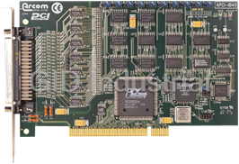
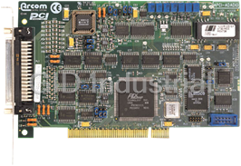
Arcom APCI-IB40 40-Channel Digital I/O & Counter Board
Part Number
APCI-IB40
Price
Request Quote
Manufacturer
ARCOM
Lead Time
Request Quote
Category
Digital I/O
Features
- 1MHz clock; three 8254 counter-timers
- 40 buffered, bi-directional digital I/O lines; disabled or preset on power-up
- Board access LED and User LED
- Interrupt operation
- Open-collector outputs, sink 24mA
Datasheet

Extracted Text
J591 APCI-IB40 2192-09099-000-000 APCI-IB40 Introduction The APCI-IB40 is a 32-bit PCI Local Bus I/O board which provides 40 digital I/O lines and three timer/counters. Each I/O line can be configured as either an input or an output. The board also has the facility to define the power-up/reset state of those lines to be used as outputs. The I/O connector conforms to Arcoms standard signal conditioning system (SCS) and may be used to drive a range of Signal Conditioning Boards (SCB), contact Arcom for more details. Features � 40 Digital I/O lines. � Open collector output�s can sink 24mA @ 0.45V, Sources from 4K7 Ohm at +5V. � Bit programmable for input or output. � 8254 Compatible Timer/Counter (Three 16-bit Counters). � Board Access LED (Red). � User programmable LED (Green). � 32-Bit PCI 2.1 Compliant Interface. � EEPROM for PCI Interface configuration. � 50 Way D-Type I/O Connector (Configured for Arcom Signal Conditioning System). � Operating Temperature range 0 to +70 C. � Power Consumption 220mA @ +5V. � MTBF 370,030 hours (using generic figures from MIL-HDBK-217F at ground benign). Getting Started � Power down your PC system. � Install the board in a spare PCI Slot (See Installation for CE compliance). � Power up system with MSDOS. � Run APCI.EXE (supplied on the utility disk), this will search for the board and check I/O access. If this fails, check board is correctly located. Warning This board contains C CM MO OS S devices which may be damaged by static electricity. Please ensure anti- static precautions are taken at all times when handling this board. If for any reason this board is returned to Arcom Control Systems, please ensure it is adequately packed to prevent damage during shipment. Page 1 2192-09099-000-000 J591 APCI-IB40 Operation PCI Bus Interface The PCI bus is a high speed alternative to ISA bus, it has been designed to overcome some of the limitations of ISA bus, and provide faster throughput for I/O intensive peripheral devices. PCI bus also supports Plug and Play configuration which allows the system software to allocate resources during initialisation helping to overcome resource conflicts, which might exist in a system. The APCI-IB40 uses a single chip PCI bus slave controller which is designed and manufactured by PLX Technology. This device has been designed to fully support the PCI 2.1 specification and provides plug and play software capabilities. During power-up initialisation the PCI BIOS will detect the card and assign a unique I/O address location and interrupt line. This ensures that there are no resource conflicts on the PCI bus. Multiple cards are supported through this mechanism without the need for address decode links. The PLX device contains a standard type 00H configuration space header. The table below shows the registers within this header which are required for configuration of the APCI-IB40. Configuration Space Header Offset Register Name Description Value 00-01H Vendor ID ID of PCI device manufacturer 10B5H (PLX Technology) 02-03H Device ID ID of PCI device 9050H 18-1BH Base Address Register I/O base address assigned to card 0000xxxx 2C-2DH Subsytem Vendor ID ID of board manufacturer 13ABH (ARCOM) 2E-2FH Subsystem ID ID of Board 0591H (APCI-IB40) 3CH Interrupt Line Interrupt line assigned to device 0x These registers can be accessed using PCI BIOS functions. Please contact Arcom control systems customer support team (Tel: 01223 412428) for a copy of the PCI BIOS Specification if required. Digital I/O If an I/O line is to be used as an output, writing a �0� to the corresponding bit in the output register will turn the output buffer on and it will sink current. This will force the output line to a logic �0�. When the software output enable feature is selected the output control latch must be written to with 01H before the outputs will be enabled. Since each output has an open collector drive, each line can alternatively be configured as an input by switching the output buffer OFF (Writing �1� to the corresponding bit in the output register) and then driving the line either high or pulling it low via an external source. For lines using the software output enable feature the power-up links can be used to set the outputs to a defined state at power on. If the output buffers are permanently enabled the power up state can not be guaranteed. Page 2 J591 APCI-IB40 2192-09099-000-000 Electrical configuration of each digital I/O line: Note:- If an I/O line is to be configured as an input, it is necessary that the power-up link for that group of lines is set in the �A� position. This means that any lines to be used as outputs will be set high, or OFF. A good rule is to keep the lines to be used as inputs and those to be used as outputs in separate groups of eight I/O lines. Timer/Counter The APCI-IB40 contains an 8254 compatible timer/counter. This device contains three 16-bit counters, each with its own clock input, gate input and output pin. The clock input to counter 0 is driven from an on board frequency source which is selected by LK1 to be 1MHZ, 100KHZ or 10KHZ, and the output can be used to generate an interrupt signal. The clock and gate inputs for the remaining counters are derived from I/O lines 24-27, and the output signals are routed to I/O lines 16-17 via LK3-4. As this device is compatible with the counter/timer used on a PC/AT motherboard programming information can be found in most PC reference guides. A data sheet for this device can be obtained from our customer support team if required (Tel: 01223 412428). I/O Map The APCI-IB40 uses an indexed I/O addressing scheme to access the on-board devices and special function registers. Two consecutive I/O locations are required to implement this scheme, the base address is used to set the index value and the base+1 address is used to access the device. The I/O base address is set by the PCI BIOS during initialisation (refer to the PCI Bus section of this manual for details). A PCI BIOS function call may be used to determine the base address once the system has been initialised. Multiple boards may be used in a system as each will be given a unique address. Address Read/Write Register Name Function Base Write Index Register Write Index value Base Read Clear Interrupt Read clears pending interrupt Base+1 Read/Write Data Register Read/Write data to and from registers Page 3 2192-09099-000-000 J591 APCI-IB40 Index Registers Index Read/Write Register Name Function 00 Write Output Control Latches Bit 0-7 0 = Output �0� I/O lines 0-7 1 = Output �1� 00 Read Status of I/O lines 0-7 Bit 0-7 0 = Input �0� 1 = Input �1� 01 Write Output Control Latches Bit 0-7 0 = Output �0� I/O lines 8-15 1 = Output �1� 01 Read Status of I/O lines 8-15 Bit 0-7 0 = Input �0� 1 = Input �1� 02 Write Output Control Latches Bit 0-7 0 = Output �0� I/O lines 16-23 1 = Output �1� 02 Read Status of I/O lines 16-23 Bit 0-7 0 = Input �0� 1 = Input �1� 03 Write Output Control Latches Bit 0-7 0 = Output �0� I/O lines 24-31 1 = Output �1� 03 Read Status of I/O lines 24-31 Bit 0-7 0 = Input �0� 1 = Input �1� 04 Write Output Control Latches Bit 0-7 0 = Output �0� I/O lines 32-39 1 = Output �1� 04 Read Status of I/O lines 32-39 Bit 0-7 0 = Input �0� 1 = Input �1� 05 Read Interrupt source register Bit 0 = 1 Counter/Timer 0 Bit 1 = 1 Counter/Timer 1 Bit 2-7 Not used 06-0F N/A Not Used N/A 10 Read/Write Counter 0 Refer to manufactures data sheet for programming 11 Read/Write Counter 1 information 12 Read/Write Counter 2 13 Write Timer/Counter Control Word Special Function Register Index Read/Write Register Name Bit Function 80 Write User LED Bit 0 0 = LED off 1 = LED on Bit 1-7 Not used 81 Read Board Ident Bit 0-7 Always gives value of 00H for APCI-IB40 90 Write Output buffer enable Bit 0 0 = Outputs disabled 1 = Outputs enabled Bit 1-7 Not used. Interrupts The APCI-IB40 has one interrupt output signal which is routed to an IRQ line during the PCI BIOS initialisation. This interrupt line is expanded on board to provide two interrupt sources. These interrupts are connected to the output signals from counter 0 and counter 1. An interrupt source register has been provided at index 05H (See Index Registers table). As PCI interrupts are level triggered the interrupt service routine must determine the source of the interrupt then clear the interrupt, this is achieved by reading from the base address location. A PCI BIOS call can be used to determine the IRQ signal assigned to this card. Page 4 J591 APCI-IB40 2192-09099-000-000 Links Throughout this section a �+� indicates the default link position. Default Link Position Diagram Counter 0 Clock Frequency selection LK1 is used to select the clock frequency for counter 0. LK1 CLK 0 Input A + 1MHZ B 100KHZ 10KHZ C Timer/Counter Output Signals LK3 & LK4 are used to route the counter/timer output signals to the 50 way I/O connector. These signals share pins with I/O lines 16 and 17. timer/counter LK3 Connects channel 2 output to ribbon cable pin 24 (I/O Line 17) timer/counter LK4 Connects channel 1 output to ribbon cable pin 23 (I/O Line 16) Note:- These signals are buffered before being sent to the links, and have the same open-collector output stage as the other I/O signals. When these links are fitted the corresponding output line should be set to a logic �1� i.e. OFF. If the timer/counter outputs are not required the links should not be fitted. Power Up Output State Control LK10-14 are used to set the power up state of the digital I/O lines, which are to be used as outputs. Each link is associated with a group of eight I/O lines. Position A + Position B Link I/O Lines LK10 0-7 �1� �0� LK11 8-15 �1� �0� LK12 16-23 �1� �0� LK13 24-31 �1� �0� LK14 32-39 �1� �0� Page 5 2192-09099-000-000 J591 APCI-IB40 I/O Outputs Enabled by Software LK20-24 are used to select between permanent or software enabled output buffers. When software control is selected the output buffers are enabled by writing 01H to the software enable register at index 90H. Position A + Position B Link I/O Lines LK20 0-7 Software Permanent LK21 8-15 Software Permanent LK22 16-23 Software Permanent LK23 24-31 Software Permanent LK24 32-39 Software Permanent Note:- A jumper must be fitted to each link, to ensure correct operation. User Configuration Record Diagram User Link Default LK1 A LK3 OPEN LK4 OPEN LK10 A LK11 A LK12 A LK13 A LK14 A LK20 A LK21 A LK22 A LK23 A LK24 A Page 6 J591 APCI-IB40 2192-09099-000-000 D-50 I/O Connector (PL1) Pin Assignments The pin assignments are listed with the pin number of the D-50 connector and also the pin number when a 50-way IDC ribbon cable is connected to the D-50. The pin assignments conform to the Arcom signal conditioning system (SCS) and may be connected to an external signal conditioning board. D-type Ribbon D-type Ribbon Signal Name Signal Name Pin No. Cable Pin No. Cable 0V 1 1 I/O Line 20 26 27 0V 34 2 I/O Line 21 10 28 I/O Line 0 18 3 I/O Line 22 43 29 I/O Line 1 2 4 I/O Line 23 27 30 I/O Line 2 35 5 0V 11 31 I/O Line 3 19 6 I/O Line 34 44 32 I/O Line 4 3 7 I/O Line 24 28 33 (Gate 1 I/P) I/O Line 5 36 8 I/O Line 6 20 9 I/O Line 25 12 34 (CLK 1 I/P) I/O Line 7 4 10 37 0V 11 I/O Line 26 45 35 (Gate 2 I/P) I/O Line 32 21 12 I/O Line 8 5 13 I/O Line 27 29 36 (CLK 2 I/P) I/O Line 9 38 14 I/O Line 10 22 15 I/O Line 28 13 37 I/O Line 11 6 16 I/O Line 29 46 38 I/O Line 12 39 17 I/O Line 30 30 39 I/O Line 13 23 18 I/O Line 31 14 40 I/O Line 14 7 19 0V 47 41 I/O Line 15 40 20 I/O Line 35 31 42 0V 24 21 I/O Line 36 15 43 I/O Line 33 8 22 I/O Line 37 48 44 I/O Line 16 41 23 I/O Line 38 32 45 (CT1 O/P) I/O Line 39 16 46 I/O Line 17 25 24 �12V 49 47 (CT2 O/P) +12V 33 48 I/O Line 18 9 25 +5V 17 49 I/O Line 19 42 26 +5V 50 50 Page 7 2192-09099-000-000 J591 APCI-IB40 Installation for CE Compliance To maintain compliance with the requirements of the EMC directive (89/336/EEC), this product must be correctly installed. The PC system in which the board is housed must be CE compliant as declared by the manufacturer. The type of external I/O cable required can be chosen according to the notes below: 1. Remove the cover of the PC observing any additional instructions of the PC manufacturer. 2. Locate the board in a spare PCI slot and press gently but firmly into place. 3. Ensure that the metal bracket attached to the board is fully seated. 4. fit the bracket clamping screw and firmly tighten this on the bracket. Note:- Good contact of the bracket to the chassis is essential. 5. Replace the cover of the PC observing any additional instructions of the PC manufacturer. Cable Cable length 1 Metre or less : Ribbon cable satisfactory. Cable 1 Metre to 3 Meters : Commerial screened cable. > 3 Meters or noisy environment : Use fully screened cable with metal backshells e.g. Arcom CAB50CE The following standards have been applied to this product: BS EN50081-1 : 1992 Generic Emissions Standard, Residential, Commercial, Light Industry BS EN50082-1 : 1992 Generic Immunity Standard, Residential, Commercial, Light Industry BSEN55022 : 1995 ITE Emissions, Class B, Limits and Methods. Page 8 J591 APCI-IB40 2192-09099-000-000 Revision History Manual PCB Comments Issue A V1 Iss 2 980313 First released in this format. Page 9 2192-09099-000-000 J591 APCI-IB40 Product Information Full information about other Arcom products is available via the F Fa ax x--o on n--D De em ma an nd d S Sy ys stte em m, (Telephone Numbers are listed below), or by contacting our W We eb bS Siit te e in the UK at: w ww ww w. .a ar rc co om m. .c co o. .u uk k , or in the US at: w ww ww w. .a ar rc co om mc co on nt tr ro olls s. .c co om m U Us se ef fu ul l C Co on nt ta ac ct t I In nf fo or rm ma at tiio on n C Cu us st to om me er r S Su up pp po or rt t S Sa alle es s Tel: +44 (0)1223 412 428 Tel: +44 (0)1223 411 200 Fax: +44 (0)1223 403 400 Fax: +44 (0)1223 410 457 E-mail: support@arcom.co.uk E-mail sales@arcom.co.uk or for the US E-mail icpsales@arcomcontrols.com U Un ni it te ed d K Ki in ng gd do om m U Un ni it te ed d S St ta at te es s F Fr ra an nc ce e G Ge er rm ma an ny y B Be el lg gi iu um m Arcom Control Systems Ltd Arcom Control Systems Inc Arcom Control Systems Kostenlose Infoline: Groen Nummer: Clifton Road 13510 South Oak Street Centre d�affaires SCALDY Tel: 0130 824 511 Tel: 0800 7 3192 Cambridge CB1 4WH, UK Kansas City MO 64145 USA 23 rue Colbert Fax: 0130 824 512 Fax: 0800 7 3191 Tel: 01223 411 200 Tel: 816 941 7025 7885 SAINT QUENTIN FoD: 0130 860 449 Fax: 01223 410 457 Fax: 816 941 0343 Cedex, FRANCE N Ne et th he er rl la an nd ds s FoD: 01223 240 600 FoD: 800 747 1097 Tel: 0800 90 84 06 I It ta al ly y Gratis 06 Nummer: Fax: 0800 90 84 12 NumeroVerde: Tel: 06022 11 36 FoD: 0800 90 23 80 FoD: 1678 73600 Fax: 06022 11 48 The choice of boards or systems is the responsibility of the buyer, and the use to which they are put cannot be the liability of Arcom Control Systems Ltd. However, Arcom�s sales team is always available to assist you in making your decision. ' 1997 Arcom Control Systems Ltd Arcom Control Systems is a subsidiary of Fairey Group Plc. Specifications are subject to change without notice and do not form part of any contract. All trademarks recognised. Arcom Control Systems Ltd operate a company-wide quality management system which has been certified by the British Standards Institution (BSI) as compliant with ISO9001:1994 Page 10
Frequently asked questions
How does Industrial Trading differ from its competitors?

Is there a warranty for the APCI-IB40?
Which carrier will Industrial Trading use to ship my parts?
Can I buy parts from Industrial Trading if I am outside the USA?
Which payment methods does Industrial Trading accept?


What they say about us
FANTASTIC RESOURCE
One of our top priorities is maintaining our business with precision, and we are constantly looking for affiliates that can help us achieve our goal. With the aid of GID Industrial, our obsolete product management has never been more efficient. They have been a great resource to our company, and have quickly become a go-to supplier on our list!
Bucher Emhart Glass
EXCELLENT SERVICE
With our strict fundamentals and high expectations, we were surprised when we came across GID Industrial and their competitive pricing. When we approached them with our issue, they were incredibly confident in being able to provide us with a seamless solution at the best price for us. GID Industrial quickly understood our needs and provided us with excellent service, as well as fully tested product to ensure what we received would be the right fit for our company.
Fuji
HARD TO FIND A BETTER PROVIDER
Our company provides services to aid in the manufacture of technological products, such as semiconductors and flat panel displays, and often searching for distributors of obsolete product we require can waste time and money. Finding GID Industrial proved to be a great asset to our company, with cost effective solutions and superior knowledge on all of their materials, it’d be hard to find a better provider of obsolete or hard to find products.
Applied Materials
CONSISTENTLY DELIVERS QUALITY SOLUTIONS
Over the years, the equipment used in our company becomes discontinued, but they’re still of great use to us and our customers. Once these products are no longer available through the manufacturer, finding a reliable, quick supplier is a necessity, and luckily for us, GID Industrial has provided the most trustworthy, quality solutions to our obsolete component needs.
Nidec Vamco
TERRIFIC RESOURCE
This company has been a terrific help to us (I work for Trican Well Service) in sourcing the Micron Ram Memory we needed for our Siemens computers. Great service! And great pricing! I know when the product is shipping and when it will arrive, all the way through the ordering process.
Trican Well Service
GO TO SOURCE
When I can't find an obsolete part, I first call GID and they'll come up with my parts every time. Great customer service and follow up as well. Scott emails me from time to time to touch base and see if we're having trouble finding something.....which is often with our 25 yr old equipment.
ConAgra Foods