

 Manufacturers
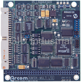
ARCOM AIM104-MULTI-IO
Description
Arcom AIM104-MULTI-IO PC Modules - 16-channel 12-bit ADC, 2-channel 12-bit DAC, 8-channel Opto-Isolated Digital Inputs Module. Module fitted with digital inputs, analogue outputs and analogue inputs.
Part Number
AIM104-MULTI-IO
Price
Request Quote
Manufacturer
ARCOM
Lead Time
Request Quote
Category
PC/104plus-Express Modules
Specifications
Calibration accuracy @ 25° ±2 LSB (MAX) (REF
5.0V)
Channel Output impedance
Vout
Channel update time
320µsec/channel
Gain error (cal @ 25°)
0.35% (-20°C to +70°C typ/0°C to 70°C max
Linearity
Differential Non-linearity ±0.5LSB (MAX) | Integral Non-linearity
Offset error
±4mV (-20°C to +70°C typ/0°C to 70°C max)
Two 12-bit analogue outputs
Current sink: 0-25mA and Bipolar voltage: -5v to +5v
Voltage overhead at Iout pin
7.5V(MIN)
Features
- 12-bit ADC inputs, link-selectable as either 16 single-ended or 8 differential channels
- All digital inputs include a fixed 10ms input debounce filter
- Eight opto-isolated digital inputs
- Maximum acquisition rate: 2000 conversions/sec
- Module access LED
- Two 12-bit DAC outputs, voltage or current loop
Datasheet

Extracted Text
2192-09190-000-000 AIM104-MULTI/IO Assembly Kit Each AIM104 module is supplied with a mounting kit to secure the module. Handling All AIM104�s contain CMOS devices which could be damaged in the event of static electricity being discharged through them. At all times please observe anti-static precautions when handling the board and always unpack and install the board in an anti-static working area. Software A Utility Disk is supplied with your AIM104. It contains a host of software utilities designed specifically for each AIM104. Please refer to the README.TXT file on the disk for further information. It also includes a test program EXAMP-01.EXE which may be used to confirm access to the board. A summary of the software drivers can be found in the AIM104-Software Library. Introduction The AIM104-MULTI-IO is an 8-bit PC/104 module providing 8 opto-isolated digital inputs, 2 analogue outputs (Voltage or Current Loop) and 16 single ended or 8 differential analogue inputs. The module provides up to 1000V electrical isolation between your PC/104 based control system and the electrical system under control. Isolation between adjacent channels is limited by the wiring and connectors to 30V. The module is supplied in three configurations: AIM104-MULTI-IO Module fitted with digital inputs, analogue outputs and analogue inputs. AIM104-ADC16/IN8 Module fitted with digital inputs and analogue inputs only. AIM104-DAC2/IN8 Module fitted with digital inputs and analogue outputs only. The board includes jumper options for selecting all analogue inputs as 16 single ended or 8 differential. All digital inputs include a fixed 10ms debounce filter. Features DAC � Two 12-bit analogue outputs: Current sink: 0-25mA AND Bipolar voltage: -5v to +5v � Channel Output impedance: Vout = <10Ω � Voltage overhead at Iout pin 7.5V(MIN) � Channel update time: 320μsec/channel � Calibration accuracy @ 25�C: –2 LSB (MAX) (REF=5.0V) � Linearity: Differential Non-linearity = –0.5LSB (MAX) Integral Non-linearity = –3.5LSB (MAX) � Offset error –4mV (-20�C to +70�C typ/0�C to 70�C max) � Gain error (cal @ 25�) 0.35% (-20�C to +70�C typ/0�C to 70�C max) Page 1 2192-09190-000-000 J541 AIM104-MULTI/IO ADC � Bipolar analogue input range: -5v to +5v � 12-bit analogue inputs configured as: 16 channel single ended OR 8 channel differential � Channel Input impedance: 10MΩ//10pF typ � Conversion time: 500μsec/channel � Calibration accuracy @ 25�C: Adjustable � Relative accuracy @ 25�C: –2LSB (-5V to +5V) � Linearity: Differential Non-linearity = –1LSB ( No missing codes) � Gain error (cal @ 25�) 0.5% (-20�C to +70�C typ/0�C to 70�C max) 8 channels of isolated digital input. � Digital input switching voltage range: 10V to 30V � Maximum digital input frequency: 50Hz � Debounce filter time constant: 10ms � All digital inputs include reverse input protection diodes. � Link selectable base address. � Board status register. � Module access LED (on all decoded addresses) � 8-bit PC/104 (IEEE996) bus interface. � EMC guard plane. � Operating temperature range, -20�C to +70�C. � Power consumption from the PC/104 host: AIM104-MULTI-IO: Max 480mA @+5v AIM104-ADC16/IN8: Max 410mA @+5v AIM104-DAC2/IN8: Max 380mA @+5v � MTBF: (using generic figures from MIL-HDBK-217F at ground benign) AIM104-MULTI-IO 267,320 hours AIM104-ADC16/IN8 303,060 hours AM104-DAC2/IN8 331,190 hours Page 2 J541 AIM104-MULTI/IO 2192-09190-000-000 Operation Digital Input Operation The status of each digital input is read from the base address, where the bit number corresponds to the channel number. When an input is switched ON, the value read by the host will be �0�. Each input is configured as follows: DAC Operation DAC data is written to DAC L-byte and DAC H-byte registers in accordance with the I/O map. Bit�s 4 - 7 of the H-byte designate the DAC channel number, A value of �0� in this position writes the data to DAC channel 0 and a value of �F� writes the data to DAC channel 1. The �BUSY status� register must be checked and the �BUSY� flag bit clear before a new value is written. Page 3 2192-09190-000-000 J541 AIM104-MULTI/IO ADC Operation ADC conversion is initiated when multiplexer channel data is written to the �ADC channel and start conversion� register. Conversion data may be read from the ADC L-byte and ADC H-byte registers when the status bit in the �BUSY status� register indicates that a conversion is complete. Only the �BUSY status� register and the �opto inputs� register should be accessed while the board is in the Busy state. Accessing other registers before the status bit is cleared for both ADC and DAC cycles may result in data corruption. ADC Input Range The standard analogue input range for the AIM104-MULTI I/O and AIM104-ADC16/IN8 is –5V. Signals with greater span than this , such as –10V, can buffered with a simple amplifier circuit. The values shown below are suggested values only, and may be varied to suit the application. +12V 2R + AIM104-MULTI I/O DIFFERENTIAL ± 10V SIGNAL input INPUT 2R - C R = 100k -12V R C = 1μF R 0VA C Page 4 J541 AIM104-MULTI/IO 2192-09190-000-000 Links The base address of the module is set using LK1; inserting a jumper selects a �0� for the address line value. Default Link Position [Address is 180h] User Configuration Record A2 A2 A3 A3 A4 A4 A5 A5 A6 A6 LK3 LK3 A7 A7 A8 A8 A LK4 B A LK4 B A9 A9 LK1 LK1 Links LK3 and LK4 select the analogue input channel configurations. For 16 channel single ended operation LK3 should be inserted and LK4 should be inserted in position �A�, PDIFF should be used as the ground reference in this configuration. For 8 channel differential operation LK3 should be removed and LK4 should be inserted in position �B�. Mode LK3 LK4 16 CH SE IN A 8 CH DIFF OUT B The board �access� LED provides a momentary flash when the board is successfully accessed. The module registers are accessed at the following locations: Address Read/Write Register Name Register Function Base Read Opto Inputs Bit 0 -7 0 = Input ON 1 = Input OFF Base +1 Write ADC channel select and start Bit 0 -3 (Mux A) conversion Bit 4 - 7 (Mux B) Base +1 Read BUSY status Bit 0 (0 = BUSY, 1 = CLEAR) Base +2 Read ADC L-byte Bit 0 - 7 (D0 .. D7) Base +3 Read ADC H-byte Bit 0 - 3 (D8 .. D11) Base +2 Write DAC L-byte Bit 0 - 7 (D0 .. D7) Base +3 Write DAC H-byte and transfer Channel Bit 0 - 3 (D8 .. D11) Bit 4 - 7 (0 = CH0 F = CH1) ADC Channel Select Byte (Base +1) Differential channel 0 1 2 3 4 5 6 7 Select Byte 88 99 AA BB CC DD EE FF Single Ended channel 0 1 2 3 4 5 6 7 8 9 10 11 12 13 14 15 Select Byte 08 80 09 90 0A A0 0B B0 0C C0 0D D0 0E E0 0F F0 Page 5 2192-09190-000-000 J541 AIM104-MULTI/IO Connector (PL2) Pin Assignments Pin No. Function Pin No. Function 1 Common cathode input 2 Byte 0 - bit 0 anode 3 Byte 0 - bit 1 anode 4 Byte 0 - bit 2 anode 5 Byte 0 - bit 3 anode 6 Byte 0 - bit 4 anode 7 Byte 0 - bit 5 anode 8 Byte 0 - bit 6 anode 9 Byte 0 - bit 7 anode 10 Common cathode input 11 0VA 12 Analogue Input + Ch 0 (Ch 0) 13 Analogue Input - Ch 0 (Ch 1) 14 Analogue Input + Ch 1 (Ch 2) 15 Analogue Input - Ch 1 (Ch 3) 16 Analogue Input + Ch 2 (Ch 4) 17 Analogue Input - Ch 2 (Ch 5) 18 Analogue Input + Ch 3 (Ch 6) 19 Analogue Input - Ch 3 (Ch 7) 20 PDIFF 21 0VA 22 Analogue Input + Ch 4 (Ch 8) 23 Analogue Input - Ch 4 (Ch 9) 24 Analogue Input + Ch 5 (Ch 10) 25 Analogue Input - Ch 5 (Ch 11) 26 Analogue Input + Ch 6 (Ch 12) 27 Analogue Input - Ch 6 (Ch 13) 28 Analogue Input + Ch 7 (Ch 14) 29 Analogue Input - Ch 7 (Ch 15) 30 PDIFF 31 0VA 32 n/c 33 n/c 34 Analogue Ch 0 Current Loop 35 OVA 36 Analogue Ch 0 Return 37 n/c 38 Analogue Ch 1 Current Loop 39 OVA 40 Analogue Ch 1 Return 41 n/c 42 n/c 43 Analogue Ch 0 Vout 44 Analogue Ch 1 Vout 45 n/c 46 n/c 47 n/c 48 n/c 49 n/c 50 n/c N No ot te e: Single Ended Channels shown (Ch x) Calibration The AIM104-MULTI-IO is pre-calibrated and should require no user calibration before operation. Periodically the calibration may be checked and if required adjustments to the on board reference can be made. Adjust the multi turn trimmer VR1 while monitoring TP10. The voltage at TP10 should be 5.0v. Further calibration is achieved through software. EMC Issues The opto-isolation provides a good barrier for noise emissions generated by the high frequency host PC/104 system. The AIM104-MULTI-IO includes additional components on board to minimise high frequency noise transfer. This filtering requires that the earth tab supplied with the module is connected by a good earth wire to the chassis of the system. If the electronic system requires input protection against high voltage transient (to meet CE requirements) it is recommended that an external interface board is located at the point where the external wiring enters the electronic system enclosure. Page 6 J541 AIM104-MULTI/IO 2192-09190-000-000 Page 7 2192-09190-000-000 J541 AIM104-MULTI/IO Page 8 J541 AIM104-MULTI/IO 2192-09190-000-000 Revision History Manual PCB Comments Issue A V1 I2 960920 First full release of manual. (Aim104 Module Manual). Issue B V1 I3 961223 Edits to J538, J541, J559 & Aim104 Software Library. (Aim104 Module Manual). Issue C V1 I3 970604 [ECO 2494, 2502, 2516] (Aim Module Manual). Issue D V1 I3 980303 [ECO 2679] (Manual split up into Datasheets.) NOTE: 960920- The Arcom Aim104 Modules were all put together in one manual (2192-08164-000-000), then updated to Issues B and C (2192-08240-000-000 & 2192-08521-000-000). During the lifetime of Issue C it was decided that the Aim Module Maual should be split into separate Datasheets [ECO 2679]. Hence, the Revision History for Issues A, B & C of the manual refer to the Aim Module Manual as was. Page 9 2192-09190-000-000 J541 AIM104-MULTI/IO Product Information F Fa ax x- -o on n- -D De em ma an nd d S Sy ys st te em m Full information about other Arcom products is available via the , (Telephone Numbers are listed below), or by contacting our W We eb bS Si it te e in the UK at: w ww ww w. .a ar rc co om m. .c co o. .u uk k or in the US at: w ww ww w. .a ar rc co om mc co on nt tr ro ol ls s. .c co om m U Us se ef fu ul l C Co on nt ta ac ct t I In nf fo or rm ma at ti io on n C Cu us st to om me er r S Su up pp po or rt t S Sa al le es s o or r f fo or r t th he e U US S: : E E- -m ma ai il l Tel: +44 (0)1223 412 428 Tel: +44 (0)1223 411 200 icpsales@arcomcontrols.com Fax: +44 (0)1223 403 409 Fax: +44 (0)1223 410 457 E-mail: support@arcom.co.uk E-mail sales@arcom.co.uk U Un ni it te ed d K Ki in ng gd do om m U Un ni it te ed d S St ta at te es s B Be el lg gi iu um m G Ge er rm ma an ny y I It ta al ly y Arcom Control Systems Ltd Arcom Control Systems Inc Groen Nummer: Kostenlose Infoline: Numero Verde: Clifton Road 13510 South Oak Street Tel: 0800 7 3192 Tel: 0130 824 511 Tel: 1677 90841 Cambridge CB1 7EA, UK Kansas City MO 64145 USA Fax: 0800 7 3191 Fax: 0130 824 512 Fax: 1677 80841 Tel: 01223 411 200 Tel: 816 941 7025 FoD: 0130 860 449 FoD: 1678 73600 F Fr ra an nc ce e Fax: 01223 410 457 Fax: 816 941 0343 Numero Vert N Ne et th he er rl la an nd ds s FoD: 01223 240 600 FoD: 800 747 1097 Tel: 0800 90 84 06 Gratis 0800 Nummer: Fax: 0800 90 84 12 Tel: 0800 0221136 FoD: 0800 90 23 80 Fax: 0800 022114 Whilst Arcom�s sales team is always available to assist you in making your decision, the final choice of boards or systems is solely and wholly the responsibility of the buyer. Arcom�s entire liability in respect of the boards or systems is as set out in Arcom�s standard terms and conditions of sale. If you intend to write your own low level software, you can start with the source code on the disk which is supplied. This is example code only to illustrate use on Arcom�s products. It has not been commercially tested. No warranty is made in respect of this code and Arcom shall incur no liability whatsoever or howsoever arising from any use made of the code. ' 1999 Arcom Control Systems Ltd Arcom Control Systems is a subsidiary of Fairey Group Plc. All trademarks recognised. Arcom Control Systems Ltd operate a company-wide quality management system which has been certified by the British Standards Institution (BSI) as compliant with ISO9001:1994 Page 10
Frequently asked questions
How does Industrial Trading differ from its competitors?

Is there a warranty for the AIM104-MULTI-IO?
Which carrier will Industrial Trading use to ship my parts?
Can I buy parts from Industrial Trading if I am outside the USA?
Which payment methods does Industrial Trading accept?
Why buy from GID?

Quality
We are industry veterans who take pride in our work

Protection
Avoid the dangers of risky trading in the gray market

Access
Our network of suppliers is ready and at your disposal

Savings
Maintain legacy systems to prevent costly downtime

Speed
Time is of the essence, and we are respectful of yours
Related Products

Arcom AIM104-ADC16/IN8 PC Modules - Opto-Isolated 16-channel 12-bit ADC, Opto-Isolated 8-channel Dig...
Request a Quote

The quote request has been received
Close

Facing challenges or have inquiries? Feel free to contact us!
Call Us +1-469-283-2440
What they say about us
FANTASTIC RESOURCE
One of our top priorities is maintaining our business with precision, and we are constantly looking for affiliates that can help us achieve our goal. With the aid of GID Industrial, our obsolete product management has never been more efficient. They have been a great resource to our company, and have quickly become a go-to supplier on our list!
Bucher Emhart Glass
EXCELLENT SERVICE
With our strict fundamentals and high expectations, we were surprised when we came across GID Industrial and their competitive pricing. When we approached them with our issue, they were incredibly confident in being able to provide us with a seamless solution at the best price for us. GID Industrial quickly understood our needs and provided us with excellent service, as well as fully tested product to ensure what we received would be the right fit for our company.
Fuji
HARD TO FIND A BETTER PROVIDER
Our company provides services to aid in the manufacture of technological products, such as semiconductors and flat panel displays, and often searching for distributors of obsolete product we require can waste time and money. Finding GID Industrial proved to be a great asset to our company, with cost effective solutions and superior knowledge on all of their materials, it’d be hard to find a better provider of obsolete or hard to find products.
Applied Materials
CONSISTENTLY DELIVERS QUALITY SOLUTIONS
Over the years, the equipment used in our company becomes discontinued, but they’re still of great use to us and our customers. Once these products are no longer available through the manufacturer, finding a reliable, quick supplier is a necessity, and luckily for us, GID Industrial has provided the most trustworthy, quality solutions to our obsolete component needs.
Nidec Vamco
TERRIFIC RESOURCE
This company has been a terrific help to us (I work for Trican Well Service) in sourcing the Micron Ram Memory we needed for our Siemens computers. Great service! And great pricing! I know when the product is shipping and when it will arrive, all the way through the ordering process.
Trican Well Service
GO TO SOURCE
When I can't find an obsolete part, I first call GID and they'll come up with my parts every time. Great customer service and follow up as well. Scott emails me from time to time to touch base and see if we're having trouble finding something.....which is often with our 25 yr old equipment.
ConAgra Foods