

 Manufacturers
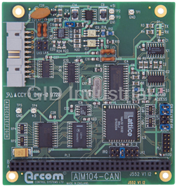
ARCOM AIM104-CAN
Description
Single Channel Opto-Isolated CAN interface module supporting the Philips SJA1000 Controller (CAN 2.0B compliant) PC104 board
Part Number
AIM104-CAN
Price
Request Quote
Manufacturer
ARCOM
Lead Time
Request Quote
Category
I/O Module
Specifications
Form Factor
PC/104
Base Address Range
0 to 3Eo hex
Bus Interface
IEEE-P996.1
Controller Area Network Interface
Philips SJA1000
I/O Address Space
32 bytes, link-selectable base address
Interrupts
Link-selectable IRQ2 to 7
MTBF
550,000hrs
Operating Temperature
-25 to +70°C
Power Consumption
180mA (typ) @ +5V
Storage Temperature
-40 to +125°C
Features
- 128 byte serial EEPROM for parameter storage
- A DeviceNet compatible breakout module is available for the AIM104-CAN (contact Arcom for module support for DeviceNet)
- Controller Area Network interface (Philips SJA1000)
- Module access LED
- Onboard link-selectable CAN termination network
- Philips SJA1000 CAN controller
- Single-channel opto-isolated CAN interface
- Supports CAN ISO11898 network connection (CAN 1.1 and 2.0a)
- Three bi-colour diagnostic LEDs, driven by output port
- Up to 1Mbit per sec baud rate
Datasheet

Extracted Text
J552 AIM104-CAN 2192-09556-000-000 AIM104-CAN Introduction The AIM104-CAN is an 8-bit PC/104 module providing a single channel, optically isolated, Controller Area Network (CAN) interface. In addition, the board is fitted with an E²PROM for configuration information and an output port for driving three bi-colour LED’s. Features • Single channel, opto isolated CAN (ISO11898) interface utilising Philips SJA1000 Standalone CAN Controller. • Up to 1Mb/s baud rate • Supports the following CAN standards: CAN 2.0a - Error passive to extended 29 bit identifiers (BasicCAN) CAN 2.0b - Full support for CAN with extended 29 bit Identifiers • On board link-selectable CAN termination network (124R) • Link selectable slew rate control for CAN line drivers • Fieldbus power ground signal fault protection • Diagnostic LEDs: Module access LED CAN bus activity indicator LED CAN bus transmit indicator LED • On board serial E²PROM (128 bytes) for parameter storage • 6 bit output port to drive 3 bi-colour indicator LEDs (24mA source/sink) • 8 bit PC/104 (IEEE996) interface • Link selectable base address (on 32 byte boundary) • Link selectable interrupt (IRQ2,3,4,5,6,7) • EMC guard plane • Operating temperature range: -20°C to +70°C • Power requirements: PC/104 Interface: +5V @ 180mA typical Isolated CAN: +9V to +27V @ 50mA max • MTBF: 552,900 hours (using generic failure rates from MIL-HDBK-217F at ground benign) Operation The AIM104-CAN uses the Philips SJA1000 device to handle all aspects of the CAN communications protocol. The 32 registers of the SJA1000 are mapped directly into the I/O space of the module and are accessed by standard input and output operations from the host CPU board. An interrupt can be generated by the SJA1000 upon certain conditions occurring (transmit, receive and error conditions) which is routed to either IRQ2,3,4,5,6 or 7 by a link. Note that the AIM/104- CAN does not support PC/104 interrupt sharing. In addition to the registers of the SJA1000, the AIM104-CAN implements two other registers. One register is used to access the on-board E²PROM and the other for accessing the off-board indicator LEDs (nominally three bi-colour LEDs). Full software support for the CAN driver device, the E²PROM and the indicator LEDs is provided in the AIM104-CAN software library. In addition, higher level protocol support may be purchased from Arcom. Contact Arcom sales for further details. Page 1 CONTROL SYSTEMS J552 AIM104-CAN 2192-09556-000-000 Connection of Bi-Colour LEDs The AIM104-CAN has a six bit output port that is designed to drive three Bi-colour indicator LEDs. The following circuit should be used for connecting these LEDs: I/O Map Address Device** Reg Name Access Function Base +0x00 SJA1000 CR R/W Control Register Command Register Base +0x01 SJA1000 CMR Write Only Status Register Base +0x02 SJA1000 SR Read Only Interrupt Register Base +0x03 SJA1000 IR Read Only Acceptance Code Register Base +0x04 SJA1000 AC R/W* Acceptance Mask Register Base +0x05 SJA1000 AM R/W* Bus Timing Register 0 Base +0x06 SJA1000 BTR0 R/W* Bus Timing Register 1 Base +0x07 SJA1000 BTR1 R/W* Output Control Register Base +0x08 SJA1000 OCR R/W* Test Register (Used for Philips Production Test Only) Base +0x09 SJA1000 TR - Transmit Buffer (2 descriptor bytes + 8 data bytes) Base +0x0A SJA1000 TB R/W* Receive Buffers (2 descriptor bytes + 8 data bytes Base +0x14 SJA1000 RB0/RB1 Read Only each) Base +0x1F SJA1000 CDR R/W Clock Divisor Register Base +0x20 SJA1000 LED Write Only Output Register for bi-colour LEDs Base +0x21 SJA1000 E²PROM R/W I/O Register for accessing the EEPROM *Access to these registers may be restricted depending on the operating mode or conditions within the . SJA1000 ** Full information on the 82C200 can be found in the appropriate data sheet available from a Philips distributor. Page 2 CONTROL SYSTEMS J552 AIM104-CAN 2192-09556-000-000 PeliCAN address alocation -RESET mode Address Device Reg Name Access Description Base +0x00 SJA1000 MOD Read/Write Mode Register Base +0x01 SJA1000 CMR Write Only Command Register Base +0x02 SJA1000 SR Read Only Status Register Base +0x03 SJA1000 IR Read Only Interrupt Register Base +0x04 SJA1000 IER Read/Write Interrupt Enable Register Base +0x05 SJA1000 reserved reserved Base +0x06 SJA1000 BTR0 Read/Write Bus Timing 0 Register Base +0x07 SJA1000 BTR1 Read/Write Bus Timing 1 Register Base +0x08 SJA1000 OCR Read/Write Output Control Register Base +0x09 SJA1000 test Used for Philips Production Test Only Base +0x0A SJA1000 reserved reserved Base +0x0B SJA1000 ALC Read Only Arbitration Lost Capture Register Base +0x0C SJA1000 ECC Read Only Error Code Capture Register Base +0x0D SJA1000 EWLR Read/Write Error Warning Limit Register Base +0x0E SJA1000 RXERR Read/Write Receive Error Counter Register Base +0x0F SJA1000 TXERR Read/Write Transmit Error Counter Register Base +0x10 SJA1000 ACR0 Read/Write Acceptance Code Register 0 Base +0x11 SJA1000 ACR1 Read/Write Acceptance Code Register 1 Base +0x12 SJA1000 ACR2 Read/Write Acceptance Code Register 2 Base +0x13 SJA1000 ACR3 Read/Write Acceptance Code Register 3 Base +0x14 SJA1000 AMR0 Read/Write Acceptance Mask Register 0 Base +0x15 SJA1000 AMR1 Read/Write Acceptance Mask Register 1 Base +0x16 SJA1000 AMR2 Read/Write Acceptance Mask Register 2 Base +0x17 SJA1000 AMR3 Read/Write Acceptance Mask Register 3 Base +0x18 SJA1000 reserved reserved Base +0x19 SJA1000 reserved reserved Base +0x1A SJA1000 reserved reserved Base +0x1B SJA1000 reserved reserved Base +0x1C SJA1000 reserved reserved Base +0x1D SJA1000 RMC Read Only Receive Message Counter Register Base +0x1E SJA1000 RBSA Read/Write Receive Buffer Start Address Register Base +0x1F SJA1000 CDR Read/Write Clock Divider Register Base +0x20 Module LED Write Only Output Register for bi-colour LEDs 2 2 Base +0x21 Module E PROM Read/Write I/O Register for E PROM access Page 3 CONTROL SYSTEMS J552 AIM104-CAN 2192-09556-000-000 PeliCAN address alocation -Operating mode Address Device Reg Name Access Description Base +0x00 SJA1000 MOD Read/Write Mode Register Base +0x01 SJA1000 CMR Write Only Command Register Base +0x02 SJA1000 SR Read Only Status Register Base +0x03 SJA1000 IR Read Only Interrupt Register Base +0x04 SJA1000 IER Read/Write Interrupt Enable Register Base +0x05 SJA1000 reserved reserved Base +0x06 SJA1000 BTR0 Read Only Bus Timing 0 Register Base +0x07 SJA1000 BTR1 Read Only Bus Timing 1 Register Base +0x08 SJA1000 OCR Read Only Output Control Register Base +0x09 SJA1000 test Used for Philips Production Test Only Base +0x0A SJA1000 reserved reserved Base +0x0B SJA1000 ALC Read Only Arbitration Lost Capture Register Base +0x0C SJA1000 ECC Read/Write Error Code Capture Register Base +0x0D SJA1000 EWLR Read Only Error Warning Limit Register Base +0x0E SJA1000 RXERR Read Only Receive Error Counter Register Base +0x0F SJA1000 TXERR Read Only Transmit Error Counter Register Base +0x10 SJA1000 TXB Write Transmit buffer consisting of TX frame information 1 2 to byte, TX Identifier bytes (2 for SFF , 4 for EFF ) and Base +0x1C 8 data bytes Base +0x10 SJA1000 RXB Read Receive buffer consisting of RX frame information 1 2 to byte, RX Identifier bytes (2 for SFF , 4 for EFF ) and Base +0x1C 8 data bytes Base +0x1D SJA1000 RMC Read Only Receive Message Counter Register Base +0x1E SJA1000 RBSA Read Only Receive Buffer Start Address Register 3 4 Base +0x1F SJA1000 CDR Read/Write Clock Divider Register Base +0x20 Module LED Write Only Output Register for bi-colour LEDs Base +0x21 Module EEPROM Read/Write I/O Register for EEPROM access 1 Standard Frame Format (11 bit Identifier) 2 Extended Frame Format (29 bit Identifier) 3 Note that although the SJA1000 CAN controller supports internal RAM addresses from 3210 to 12710 (TX buffer and RX FIFO), these are not accessible to the CPU board 4 Some bits of the CDR can be written in RESET mode only LED Register The LED register is used to light three external bi-colour LEDs. All bits are write only. Writing a logic 1 to any bit position causes the corresponding output to go low (active). After reset 7 6 5 4 3 2 1 0 Reserved LED2.1 LED2.0 LED1.1 LED1.0 LED0.1 LED0.0 all bits are logic 0. Reserved bits should be written as logic 0. E²PROM Register The E²PROM register directly accesses the serial lines on a 93C46 serial E²PROM as shown in the register below. All implemented bits are Read/Write except the DO bit which is read only. 7 6 5 4 3 2 1 0 Reserved SCK CS DI DO Writing a logic 1 to a bit causes the corresponding signal on the E²PROM to go high, a logic zero makes that signal low. After reset all bits in this register are logic 0. All reserved bits should be written as logic 0 for future software compatibility. Page 4 CONTROL SYSTEMS J552 AIM104-CAN 2192-09556-000-000 E²PROM Contents The E²PROM on the AIM104-CAN is shipped from the factory with a default programming. This information is divided into two records. Both records are readable using the supplied software, only the second record is writeable. Data is organised in 16 bit words and the byte order is as follows for larger data units: Object First Data Word Second Word Type Most Sig Byte Least Sig Byte Most Sig Byte Least Sig Byte 32 bit number Least Significant Word Most Significant Word Byte Arrays (strings) 2nd Byte 1st Byte 4th Byte 3rd Byte The default contents of the data are as follows: Product Data Record Offset (word) Size (words) Description Value 0x00 1 DeviceNet Vendor Id (Arcom’s) 126 0xFFFF 0x01 1 SDS Partner Number (Arcom’s) ---- 0x02 2 Unique 32 bit serial number 10552* 0x04 1 Encoded Arcom Product Number 10100* 0x05 1 Encoded Arcom Version Control Code “Arcom Control Systems” 0x06 11 Manufacturer String “6040-00552-001- 0x11 9 Stock Number String 101”* 0x1A 12 Product Description String “AIM104-CAN” 0x26 2 Date Code String mmYY “0397”* 0x28 1 16 bit CRC check mode ---- * This information may vary to reflect the build of the product that is shipped. Application Data Record Offset (word) Size (words) Description Value 0x29 1 Encoded baud rate 500 0x2A 1 Network Address 0xFFFF 0x2B 4 User Data Array {0,0,0,0} 0x2F 16 User Tag Area �� 0x3F 1 16 bit CRC check code ---- Page 5 CONTROL SYSTEMS J552 AIM104-CAN 2192-09556-000-000 Links Default Link Position Diagram (Address is 180h) User Configuration Record Address Link LK1 is the address decode link. The desired board base address is set on this link. Note that the base address can be set on any 32 byte boundary and that 34 bytes are decoded. A successful decode to any of these 34 locations will cause the red module access LED to light momentarily. Interrupt Link LK2 is the interrupt select link. This can be set for IRQ2 through to IRQ7. (Note that IRQ2 will map onto IRQ9 in an AT type PC host CPU.) PC/104 interrupt sharing is not supported by this module. Note that certain PC/104 host boards may not be able to use all of the possible link options. The following table should be used as a guide: Link Position PC Compatible* Target386EX Target188EB 4 IRQ2 4 4 IRQ3 4 4 IRQ4 4 4 4 IRQ5 4 IRQ6 4 4 4 IRQ7 * Consult your PC AT Manual to see if these IRQs are committed to other devices. Controlled Slew Rate Link LK3 is the slew rate control link. It may be removed at baud rates below 250kbaud for a slower slew on the CAN signals. This may reduce EMC emissions on unscreened twisted pair wiring. Line Termination Links LK4 and LK5 are used to attach the CAN termination network. If the AIM104-CAN is at an end on the CAN bus, terminations should be attached. To attach the termination both links should be fitted. If no termination is required both links should be removed. Page 6 CONTROL SYSTEMS J552 AIM104-CAN 2192-09556-000-000 Connector (PL2) Pin Assignments Pin No Function Pin No Pin No 1 GND 2 /LED0.0 3 /LED0.1 4 /LED1.0 5 /LED1.1 6 /LED2.0 7 /LED2.1 8 +5V 9 n/c 10 n/c 11 n/c 12 SCRN 13 CAN_L 14 CAN_H 15 V- 16 n/c 17 n/c 18 V+ 19 n/c 20 n/c Note that PL2 is used for both the isolated CAN line drivers and the non-isolated indicator LEDs. Care should be taken to separate the appropriate signals. Also note that the power for the LEDs is not protected in any way and should not be used for driving any apparatus other than the indicator LEDs. The ribbon cable can be split to form a standard CiA 9-way D-sub CAN connection. Alternatively, Arcom supply Panel Mountable breakout boards with mounted bi-colour LED’s for D- sub and screw terminal (DeviceNet) cabling. Contact Arcom Sales and enquire about SERT- DNET. Isolated CAN Transceiver The CAN transceiver on the AIM104-CAN is optically isolated from the PC/104 interface and requires external powering in order to function. A regulator on the isolated side of the circuit allows a wide range of voltage (on the V+/V-) input from 9V to 27V. The V- signal is the nominal ground reference for the line driver. A protection circuit prevents damage to the line drivers should this signal become disconnected whilst all the other signals remain connected. The optical isolation is designed to prevent ground loops and voltage drop causing problems on a distributed CAN bus system. Although the isolation voltage is in excess on 48V, the isolation must not be used as a safety feature. Page 7 CONTROL SYSTEMS J552 AIM104-CAN 2192-09556-000-000 EMC Issues The opto-isolation provides a good barrier for noise emissions generated by the high frequency host PC/104 system. The AIM104-CAN includes additional filter components on board to minimise the emissions of high frequency noise. The filter requires that the earth tab supplied with the module is connected by a good earth wire to the chassis of the system. If the electronic system requires input protection against high voltage transients (to meet CE requirements) it is recommended that an external interface board is located at the point where the external wiring enters the electronic system enclosure. Page 8 CONTROL SYSTEMS J552 AIM104-CAN 2192-09556-000-000 Circuit Diagrams Page 9 CONTROL SYSTEMS J552 AIM104-CAN 2192-09556-000-000 Page 10 CONTROL SYSTEMS J552 AIM104-CAN 2192-09556-000-000 Page 11 CONTROL SYSTEMS J552 AIM104-CAN 2192-09556-000-000 AIM104-CAN Software Library AIM104-CAN The AIM104-CAN is a more specialised module than the other modules in the range and the software structure is slightly different to accommodate this. Note: The AIM104-CAN software library refers to the BAsic CAN mode of operation. Installation System Requirements The system requirements for the AIM104-CAN software are as for the general AIM104 libraries. The setup program installs the following directory organisation for the CAN software: In order to correctly access the header files and libraries, you will need either to move them to your development directories or configure your compiler/linker in order that the necessary files can be “seen”. Refer to your compiler documentation about how to do this. Full Documentation Full documentation for the software for the AIM1104-CAn is supplied in the form of WORD 2.0 file in the documentation directory of the above directory structure. ArCan Library Functions DATA TYPES: The ArCan software uses a number of elemental data types as follows: UINT8 Unsigned 8 bit integer. UINT16 Unsigned 16 bit integer. UINT 32 Unsigned 32 bit integer. SINT8 Signed 8 bit integer. SINT16 Signed 16 bit integer. SINT32 Signed 32 bit integer. CAN Data structure used as “handle” once CAN communications are initialised. CAN_MSG A data structure that embodies both the CAN identifier, message size and data. Page 12 CONTROL SYSTEMS J552 AIM104-CAN 2192-09556-000-000 INITIALISATION ROUTINES: Before the CAN hardware can be used it is necessary to initialise the module and obtain a handle to the channel: CAN far *can_open(UINT16 ioaddr, SINT16 irqnum, UINT16 bufsiz, UINT32 baud) - Initialises a CAN channel and returns a handle void can_close(CAN far *can) - Clears the CAN hardware and frees all resources. COMMUNICATION ROUTINES: These are used for effecting communications on the CAN bus. SINT16 can_send(CAN far *can, CAN_MSG far *msg) - Transmits a message on the bus through the ring buffers. SINT16 can_fetch(CAN far *can, CAN_MSG far *msg) - Get a message from the receive ring buffer. STATUS ROUTINES: Determine the operating status of the CAN channel. SINT16 can_tx_ready(CAN far *CAN) - Determines is the transmit buffer is able to accept a message. SINT16 can_rx_ready(CAN far *can) - Determines if the receive buffer contains a message or not. SINT16 can_error(CAN far *can) - Check the error status on the CAN channel. ERROR RECOVERY: Routines used to detect and process error conditions on the CAN interface. void can_clear_errors(CAN far *can) - Clear the error flags on the CAN channel. void can_txabort(CAN far *can) - Aborts the current transmission on the CAN controller. MESSAGE IDENTIFIER FILTERING: Functions that control the acceptance of incoming messages. void can_set_filter(CAN far *CAN, UINT16 uFnum, UINT16 uAcceptCode, UINT16 uAcceptMask, SINT16 (far *FilterFn)(CAN far *, UINT16)) - Configures the hardware and software acceptance filters and user supplied function. ISR HOOKS: Other Hooks into the Interrupt Service Routine. void can_set_txcallback(CAN far *can, void (far *TxCallBackFn)(CAN far *, UINT16)) - Installs an user function called upon successful transmission of a message. void can_set_rxinform(CAN far *can, void (far *RxInformFn)(CAN far *, UINT16)) - Installs an user function called when received messages are placed in the buffer. void_can_set_error(CAN far *can, void (far *ErrorFn) (CAN far *, UINT16)) - Installs an user function to handle changes in the error state. INDICATOR LEDS: Functions to access the external indicator LEDs. SINT16 wCanLed(UINT16 uBRDAddr, UINT16 uLed, UINT16 uState) - Used to control the external indicator LEDs. E²PROM: Functions to retrieve and write the data in the E²PROM. SINT16 wCAN_ReadProcuctData (UINT16 uBrdAddr, EEP_ProductData far *pProdDat) - Reads the product data record from the E²PROM. SINT16 wCAN_ReadApplicationData(UINT16 uBrdAddr, EEP_ApplicationData far *pAppDat) - Reads the application data record from the E²PROM. SINT16 wCAN_WriteApplicationData(UINT16 uBrdAddr, EEP_ApplicationData far *pAppDat) - Recalculates the CRC in the application data record and then writes to E²PROM. Page 13 CONTROL SYSTEMS J552 AIM104-CAN 2192-09556-000-000 Revision History Manual PCB Comments Issue A V1 Iss1 970324 First published in this format. Issue B V1 Iss2 970609 [ECO2518] Issue C V1 Iss2 981007 [ECR333} Page 14 CONTROL SYSTEMS J552 AIM104-CAN 2192-09556-000-000 Product Information Full information about other Arcom products is available via the F Fa ax x- -o on n- -D De em ma an nd d S Sy ys st te em m, (Telephone W We eb bS Si it te e w ww ww w. .a ar rc co om mc co on nt tr ro ol ls s. .c co om m Numbers are listed below), or by contacting our at: U Us se ef fu ul l C Co on nt ta ac ct t I In nf fo or rm ma at ti io on n C Cu us st to om me er r S Su up pp po or rt t S Sa al le es s o or r f fo or r t th he e U US S: : E E- -m ma ai il l Tel: +44 (0)1223 412 428 Tel: +44 (0)1223 411 200 icpsales@arcomcontrols.com Fax: +44 (0)1223 403 409 Fax: +44 (0)1223 410 457 E-mail: support@arcom.co.uk E-mail sales@arcom.co.uk U Un ni it te ed d K Ki in ng gd do om m U Un ni it te ed d S St ta at te es s B Be el lg gi iu um m G Ge er rm ma an ny y I It ta al ly y Arcom Control Systems Ltd Arcom Control Systems Inc Groen Nummer: Kostenlose Infoline: Numero Verde: Clifton Road 13510 South Oak Street Tel: 0800 7 3192 Tel: 0130 824 511 Tel: 0800 790841 Cambridge CB1 7EA, UK Kansas City MO 64145 USA Fax: 0800 7 3191 Fax: 0130 824 512 Fax: 0800 780841 Tel: 01223 411 200 Tel: 816 941 7025 FoD: 0130 860 449 FoD: 0800 873600 F Fr ra an nc ce e Fax: 01223 410 457 Fax: 816 941 0343 Numero Verto FoD: 01223 240 600 FoD: 800 747 1097 N Ne et th he er rl la an nd ds s Tel: 0800 90 84 06 Gratis 0800 Nummer: Fax: 0800 90 84 12 Tel: 0800 0221136 FoD: 0800 90 23 80 Fax: 0800 022114 Whilst Arcom�s sales team is always available to assist you in making your decision, the final choice of boards or systems is solely and wholly the responsibility of the buyer. Arcom�s entire liability in respect of the boards or systems is as set out in Arcom�s standard terms and conditions of sale. If you intend to write your own low level software, you can start with the source code on the disk which is supplied. This is example code only to illustrate use on Arcom�s products. It has not been Arcom Control Systems commercially tested. No warranty is made in respect of this code and Arcom shall incur no liability Ltd operate a company- whatsoever or howsoever arising from any use made of the code. wide quality management system which has been certified by the British ' 1999 Arcom Control Systems Ltd Standards Institution Arcom Control Systems is a subsidiary of Fairey Group Plc. (BSI) as compliant with All trademarks recognised. ISO9001:1994 Page 15 CONTROL SYSTEMS J552 AIM104-CAN 2192-09556-000-000 Page 16 CONTROL SYSTEMS
Frequently asked questions
How does Industrial Trading differ from its competitors?

Is there a warranty for the AIM104-CAN?
Which carrier will Industrial Trading use to ship my parts?
Can I buy parts from Industrial Trading if I am outside the USA?
Which payment methods does Industrial Trading accept?
Why buy from GID?

Quality
We are industry veterans who take pride in our work

Protection
Avoid the dangers of risky trading in the gray market

Access
Our network of suppliers is ready and at your disposal

Savings
Maintain legacy systems to prevent costly downtime

Speed
Time is of the essence, and we are respectful of yours
Related Products

Request a Quote

The quote request has been received
Close

Facing challenges or have inquiries? Feel free to contact us!
Call Us +1-469-283-2440
What they say about us
FANTASTIC RESOURCE
One of our top priorities is maintaining our business with precision, and we are constantly looking for affiliates that can help us achieve our goal. With the aid of GID Industrial, our obsolete product management has never been more efficient. They have been a great resource to our company, and have quickly become a go-to supplier on our list!
Bucher Emhart Glass
EXCELLENT SERVICE
With our strict fundamentals and high expectations, we were surprised when we came across GID Industrial and their competitive pricing. When we approached them with our issue, they were incredibly confident in being able to provide us with a seamless solution at the best price for us. GID Industrial quickly understood our needs and provided us with excellent service, as well as fully tested product to ensure what we received would be the right fit for our company.
Fuji
HARD TO FIND A BETTER PROVIDER
Our company provides services to aid in the manufacture of technological products, such as semiconductors and flat panel displays, and often searching for distributors of obsolete product we require can waste time and money. Finding GID Industrial proved to be a great asset to our company, with cost effective solutions and superior knowledge on all of their materials, it’d be hard to find a better provider of obsolete or hard to find products.
Applied Materials
CONSISTENTLY DELIVERS QUALITY SOLUTIONS
Over the years, the equipment used in our company becomes discontinued, but they’re still of great use to us and our customers. Once these products are no longer available through the manufacturer, finding a reliable, quick supplier is a necessity, and luckily for us, GID Industrial has provided the most trustworthy, quality solutions to our obsolete component needs.
Nidec Vamco
TERRIFIC RESOURCE
This company has been a terrific help to us (I work for Trican Well Service) in sourcing the Micron Ram Memory we needed for our Siemens computers. Great service! And great pricing! I know when the product is shipping and when it will arrive, all the way through the ordering process.
Trican Well Service
GO TO SOURCE
When I can't find an obsolete part, I first call GID and they'll come up with my parts every time. Great customer service and follow up as well. Scott emails me from time to time to touch base and see if we're having trouble finding something.....which is often with our 25 yr old equipment.
ConAgra Foods