

 Manufacturers
ALLEN-BRADLEY 1746-IN16
Description
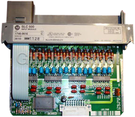
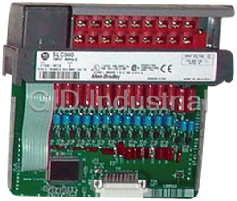
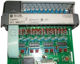
Allen Bradley 1746-IN16 I/O Module - Digital I/O, 24V AC/DC 16 I/O Points, 24V AC/DC Input Module
Part Number
1746-IN16
Price
Request Quote
Manufacturer
ALLEN-BRADLEY
Lead Time
Request Quote
Category
PLC Digital I/O Modules
Specifications
Backplane Current Draw
5V 0.085A, 24V 0.0A
CertificationÂÃ
UL listed. CSA or C-UL approved as indicated by product markings. CE compliant for all applicable directives when product or packaging is marked.
Hazardous Environment
Classà Class I, Division 2, Groups A, B, C, D Hazardous Environment
Inrush Current (max.)
0.02A (ac only)
Isolation
1500 Volts
Noise Immunity
NEMA standard ICS 2–230
Nominal Input Current
8 mA at 24V dc, 8 mA at 24V ac
Number of Inputs
16
Off-State Current (max.)
1 mA dc, 1 mA ac
Off-State Voltage (max.)
3V dc, 3V ac
Operating Humidity
5% to 95% (non-condensing)
Operating Temperature
0°C to 60°C (32°F to 140°F)À
Operating Voltage
10 to 30V dc sink, 10 to 30V ac at 47 to 63 Hz
Points per Common
16
Shock (Operating)
30Gs (all modules except relay contact). 10Gs (relay contact modules, 1746-OW, -OX, I/O Combo).
Signal Delay (max.)
dc – on : 15 ms / off : 15 ms, ac – on : 25 ms / off : 25 ms
Storage Temperature
–40°C to 85°C (–40°F to 185°F)
Vibration (Operating)
Displacement 0.015 inch peak at 5–57 Hz., Acceleration 2.5Gs at 57–2000 Hz
Voltage Category
24V ac/dc
Features
- All relay contacts are Silver Cadmium with Gold overlay
- Barrier-type terminal blocks provided on all modules
- Digital and field circuits are optically isolated
- Expands the I/O capacity of your fixed controller system
- High-density 32-Point DC I/O and fast response DC inputs are available
- LEDs indicate the status of each I/O point
- Removable terminal blocks are color coded for quick identification
- Removable terminal blocks help ease the wiring task
- Self-lifting field-wire pressure plates cut installation time
- Self-locking tabs secure the module in the chassis
- Terminal identification diagrams on each module
Datasheet

Extracted Text
Discrete Input and Output Modules (Catalog Numbers 1746-IA4, -IA8, -IA16, -IB8, -IB16, -IB32, -IC16, -IG16, -IH16, -IM4, -IM8, -IM16, -IN16, -ITB16, -ITV16, -IV8, -IV16, -IV32, -OA8, -OA16, -OAP12, -OB8, -OBP8, -OB16, -OB16E, -OBP16, -OB32, -OG16, -OV8, -OV16, -OVP16, -OV32, -OW4, -OW8, -OW16, -OX8, -IO4, -IO8, -IO12) Product Data 91-187-39 91-187-40 91-187-41 Our wide variety of input, output, and combination modules makes the SLC 500� family the smart choice for all of your small PLC applications. I/O modules are available in a wide variety of densities What’s Inside... Page including 4-, 8-, 16-, and 32-point and can interface to AC, DC, and Discrete I/O Module Summary 2 TTL voltage levels. Output modules are available with solid state Features and Benefits 4 AC, solid state DC, and relay contact type outputs. For added flexibility, combination modules are also available in I/O Module Operation 6 2-input/2-output, 4-input/4-output, and 6-input/6-output versions. Enhanced Discrete I/O Modules 8 includes: 32-Point, Fast Response, Designed and tested for industrial applications, our modules are of the High-Current Solid-State, and highest quality. The modules feature input filtering, optical isolation, Electronically Protected Modules and built-in surge protection to enhance the reliability of operation in Terms and Symbols 13 noisy industrial environments. Specifications, Wiring, and 16 Circuit Diagrams Class I, Division 2 certified by UL and CSA. CE compliant. All Fixed I/O Chassis Module 44 modules are UL 508 listed and CSA 22.2 142 approved and meet Compatibility Class I, Division 2 hazardous location requirements of both Discrete I/O Power Dissipation 46 Underwriter’s Laboratory and the Canadian Standards Association Environmental Specifications 47 (except for those noted in the module summary on page 2). For use Accessories 47 within the European Union or EEA regions, most modules have Allen-Bradley Support 48 been tested to meet Council Directive 89/336 Electromagnetic Compatibility (exceptions are listed on page 2). 2 Discrete Input and Output Modules Discrete I/O Module Summary .A ID Code Voltage Category Cat. No. Input/Output I/O Points Module Description Page AC Modules 100 100/120V ac 1746-IA4 Input 4 120V ac Input Module 16 300 100/120V ac 1746-IA8 Input 8 120V ac Input Module 16 500 100/120V ac 1746-IA16 Input 16 120V ac Input Module 16 101 200/240V ac 1746-IM4 Input 4 240V ac Input Module 16 301 200/240V ac 1746-IM8 Input 8 240V ac Input Module 16 501 200/240V ac 1746-IM16 Input 16 240V ac Input Module 16 2703 100/120V ac 1746-OA8 Output 8 120/240V ac Output Module 18 2903 100/120V ac 1746-OA16 Output 16 120/240V ac Output Module 18 � 2803 120/240V ac Output 12 High Current 120/240V ac Output Module 18 1746-OAP12 DC Modules 306 24V dc 1746-IB8 Input 8 Current Sinking DC Input Module 20 506 24V dc 1746-IB16 Input 16 Current Sinking DC Input Module 20 � 706 24V dc Input 32 Current Sinking DC Input Module 20 1746-IB32 519 24V dc 1746-ITB16 Input 16 Fast Response DC Sinking Input Module 20 509 48V dc 1746-IC16 Input 16 Current Sinking DC Input Module 20 507 125V dc 1746-IH16 Input 16 Current Sinking DC Input Module 20 320 24V dc 1746-IV8 Input 8 Current Sourcing DC Input Module 24 520 24V dc 1746-IV16 Input 16 Current Sourcing DC Input Module 24 � 720 24V dc Input 32 Current Sourcing DC Input Module 24 1746-IV32 518 24V dc 1746-ITV16 Input 16 Fast Response DC Sourcing Input Module 24 ` 515 5V dc/TTL Input 16 Current Sourcing TTL Input Module 28 1746-IG16 2713 24V dc 1746-OB8 Output 8 Current Sourcing DC Output Module 29 2913 24V dc 1746-OB16 Output 16 Current Sourcing DC Output Module 29 �´ 2920 24V dc Output 16 Current Sourcing DC Output Module 29 1746-OB16E � 3113 24V dc Output 32 Current Sourcing DC Output Module 29 1746-OB32 ´ 2721 24V dc Output 8 High Current Sourcing DC Output Module 32 1746-OBP8 � 2921 24V dc Output 16 High Current Sourcing DC Output Module 32 1746-OBP16 2714 24V dc 1746-OV8 Output 8 Current Sinking DC Output Module 34 2914 24V dc 1746-OV16 Output 16 Current Sinking DC Output Module 34 � 3114 24V dc Output 32 Current Sinking DC Output Module 34 1746-OV32 � 2922 24V dc Output 16 High Current Sinking DC Output Module 37 1746-OVP16 ` 2915 5V dc/TTL Output 16 Current Sinking TTL Output Module 38 1746-OG16 Publication 1746-2.35 Discrete Input and Output Modules 3 ID Code Voltage Category Cat. No. Input/Output I/O Points Module Description Page AC/DC Modules 510 24V ac/dc 1746-IN16 Input 16 24V ac/dc Input Module 39 � 2500 AC/DC Relay Output 4 Relay (Hard Contact) Output Module 40 1746-OW4 � 2700 AC/DC Relay Output 8 Relay (Hard Contact) Output Module 40 1746-OW8 � 2900 AC/DC Relay Output 16 Relay (Hard Contact) Output Module 40 1746-OW16 � 2701 AC/DC Relay Output 8 Isolated Relay Output Module 40 1746-OX8 Inputs – 120V ac 2 Inputs � 800 Input/Output Combination Input/Output Module 42 1746-IO4 Outputs – AC/DC Relay 2 Outputs Inputs – 120V ac 4 Inputs � 1100 Input/Output Combination Input/Output Module 42 1746-IO8 Outputs – AC/DC Relay 4 Outputs Inputs – 120V ac 6 Inputs � 1500 Input/Output Combination Input/Output Module 42 1746-IO12 Outputs – AC/DC Relay 6 Outputs � Certified for Class I, Division 2 hazardous location by CSA only. ` Not CE marked. ´ These modules carry the C-UL mark and are certified by UL per CSA requirements. Spectrum Controls, Inc. These modules are sold and supported by Spectrum Controls Inc., Modules Bellevue, Washington. For additional information, contact Spectrum at (206) 746–9481. ID Code Voltage Category Cat. No. Input/Output I/O Points Module Description AC Modules 2705 120/240V ac 1746sc-OAP8I Output 8 Isolated ac Output Module DC Modules 324 24V dc 1746sc-IB8I Input 8 Isolated DC Input Module 324 48V dc 1746sc-IC8I Input 8 48V Isolated DC Input Module AC/DC Modules 303 120V ac/dc 1746sc-IA8I Input 8 Isolated ac/dc Input Module 304 220V ac/dc 1746sc-IM8I Input 8 Isolated ac/dc Input Module Publication 1746-2.35 4 Discrete Input and Output Modules Features and Benefits Select I/O modules to exactly match your application. Combination modules allow you to have inputs and outputs in a single slot for efficient use of your chassis space. Expand the I/O capacity of your fixed controller system. Two discrete I/O modules can be added to the fixed controller’s 2-slot expansion chassis increasing the flexibility of the system. All relay contacts are Silver Cadmium with Gold overlay. Gold plating resists oxidation and tarnishing resulting from non-use. Silver Cadmium acts as an excellent conductor. High-density 32-Point DC I/O and fast response DC inputs are available. These modules allow you to apply the SLC 500 processors in a broader spectrum of control applications. LEDs indicate the status of each I/O point. INPUT IN 0 IN 1 IN 2 IN 3 IN 4 IN 5 IN 6 IN 7 IN 8 IN 9 IN 10 IN 11 IN 12 IN 13 IN 14 IN 15 AC COM AC COM Terminal identification diagrams on each module LEDs indicate the status of each I/O point. Assisting you in troubleshooting, LEDs illuminate when the proper signal is received at an input terminal, or when the processor applies power to an output terminal. Terminal identification diagrams on each module. Terminal identification diagrams are located on each module making terminal identification easier. Publication 1746-2.35 Discrete Input and Output Modules 5 Digital and field circuits are optically isolated. Self-locking tabs secure the module in the chassis. Removable terminal blocks are color coded for quick identification. Self-lifting field-wire Barrier type terminal pressure plates help reduce blocks are provided installation time. on all modules. Digital and field circuits are optically isolated. All modules feature isolation between digital and field circuits, resulting in increased noise immunity and limited damage to your system due to an electrical malfunction of the field wiring. Self-lifting field-wire pressure plates cut installation time. Wiring terminals have self-lifting pressure plates to secure two #14 AWG field wires. Removable terminal blocks help ease the wiring task. Removable terminal blocks allow you to replace the module without rewiring it (not available on all modules). Removable terminal blocks are color coded for quick identification. A matching color band is also provided on the front of the module to assist in matching the terminal block to the module. Barrier-type terminal blocks provided on all modules. Each terminal block features a barrier on three sides of each terminal to help prevent accidental shorting of field wiring. Self-locking tabs secure the module in the chassis. No tools are necessary to install or remove a module from the chassis. To install a module, you slide it into the chassis until it latches in place. Publication 1746-2.35 6 Discrete Input and Output Modules I/O Module Operation Power Supply Requirements Discrete modules receive power through the 1746 I/O chassis backplane from the associated chassis power supply. Refer to the individual module specifications for the current required from the power supply (in mA) to operate the module. You should total the current requirements for all the modules in the chassis to avoid overloading the power supply or the I/O chassis backplane. Input Modules An input module responds to an input signal in the following manner: 1. Input filtering limits the effect of voltage transients caused by contact bounce and/or electrical noise. If not filtered, voltage transients could produce false data. All input modules use input filtering. 2. Optical isolation shields backplane circuits and module logic circuits from possible damage due to electrical transients. 3. Logic circuits process the signal. 4. An input LED turns on or off indicating the status of the corresponding input device. Input Optical Logic Circuits Backplane Input Filtering Isolation LED Output Modules An output module controls the output signal in the following manner: 1. Logic circuits determine the output status. 2. An output LED indicates the status of the output signal. 3. Optical isolation separates module logic and backplane circuits from the field signal. 4. The output driver turns the corresponding output on or off. Logic Optical Backplane Output Drivers Output Circuits Isolation LED Publication 1746-2.35 Discrete Input and Output Modules 7 Surge Suppression Most output modules have built-in surge suppression to reduce the effects of high-voltage transients. However, we recommend that you use an additional suppression device if an output module is being used to control an inductive device such as: • relays • motor starters • solenoids • motors Additional suppression is especially important if your inductive device is in series with or parallel to a hard contact such as: • pushbuttons • selector switches By adding a suppression device directly across the coil of an inductive device, you will reduce the effects of voltage transients caused by interrupting the current to that inductive device and prolong the life of the switch contacts. The diagram below shows an output module with a suppression device. + DC or L1 VAC/VDC Snubber OUT 0 OUT 1 OUT 2 AC or DC OUT 3 Output Module OUT 4 OUT 5 OUT 6 OUT 7 COM DC COM or L2 Recommended surge suppressors are provided in the specifications tables. Important: Adding a suppression device across your load will defeat the fast turn-off feature of the 1746-OB16E Series B and later, -OBP8 Series B and later, -OBP16, and -OVP16 DC output modules. Refer to pages 29, 32, and 37 for more information about suppression when using the 1746-OB16E, -OBP8, -OBP16, and -OVP16, respectively. Publication 1746-2.35 8 Discrete Input and Output Modules Enhanced Discrete I/O 32-Point Modules (1746-IB32, -IV32, -OB32, -OV32) Modules The 32-point I/O modules allow you to reduce panel space requirements by wiring 32 DC input or 32 DC output devices to a module residing in one slot. These modules can be used with both modular chassis systems or fixed controllers. The 32-point modules come equipped with a 40-pin male connector on the front instead of screw terminals. This connector is designed to accept your cable fitted with the 1746-N3 mating connector. One 1746-N3 connector and 45 crimp-type contacts are packaged with each module. The other end of the cable can be wired to a user-supplied terminal block. As an alternative, 1492 prewired cables, purchased separately, can be used to connect the 32-point modules to 1492 interface modules. For more information, refer to the Accessories section on page 47. 1492-CABLExx Connects 32-point module to DIN 32-Point I/O Module rail mountable terminal block ÎÎÎÎ Male MIL-C-83503 Header ÎÎÎÎÎÎÎÎÎÎÎÎ ÎÎÎÎÎÎÎÎÎÎÎÎÎÎÎÎÎÎÎÎÎÎÎÎÎÎÎÎ ÎÎÎÎÎÎÎÎÎÎÎÎÎÎÎÎÎÎÎÎÎÎÎÎÎÎÎÎÎÎÎ ÎÎÎÎÎÎÎÎÎÎÎÎÎÎÎÎÎÎÎÎÎÎÎ ÎÎÎÎÎÎÎÎÎÎÎÎÎÎÎÎÎÎ ÎÎÎÎÎÎÎÎÎÎÎÎÎÎÎÎÎÎÎ ÎÎÎÎÎÎÎÎÎÎÎÎÎÎÎÎ ÎÎÎÎÎÎÎÎÎÎÎÎÎÎÎÎ ÎÎÎÎÎÎÎÎÎ ÎÎÎÎÎÎÎÎÎÎÎ ÎÎÎ 1492-IFM40xx DIN rail mountable terminal block Publication 1746-2.35 Discrete Input and Output Modules 9 Fast Response Input Modules (1746-ITB16, -ITV16) The fast response DC input modules provide 16 input points and are designed for high-speed applications requiring fast response to input signals from DC sensing devices. When used with an SLC 5/03� or higher processor and the Discrete Input Interrupt (DII) instruction (100 �sec polling), pulses can be read up to a frequency of 1K Hz. (It is 2K Hz if the input signals are from a gray code encoder.) Recommended wiring to an Allen-Bradley 845D Absolute Gray Code Encoder is provided on page 27. Both sinking and sourcing versions of the fast response input module are available. High-Current Solid-State Output Modules (1746-OBP8, -OAP12, -OBP16, -OVP16).B High-current solid-state output modules expand application coverage for the SLC 500 by providing the following enhanced functionality: • increased current rating • fuse protection and diagnostics • high-speed switching • excellent reliability The high current solid state output modules expand application coverage in automotive, packaging, and material handling applications by allowing the SLC 500 processor to directly control solenoids, contactors, motors, and motor starter loads (up to size 5) with continuous current requirements of up to 1A at 60�C (1746-OAP12, -OBP16, -OVP16) and 2.0A at 60�C (1746-OBP8). 1746-OAP12, -OBP16, and -OVP16 modules also provide fuse protection and blown fuse diagnostics for increased up-time. The ac output module includes two replaceable fuses (one per common), which protect the module in the event of short circuits. 1746-OBP16 and -OVP16 output modules include a replaceable fuse on the common providing short circuit protection for wiring (16 AWG or larger) to external loads. A jumper can be set on these modules to provide CPU notification and system shutdown if the module fuse blows. The modules also include a blown fuse LED to assist I/O troubleshooting. Inductive load turn-off time for 1746-OBP8 (Series B and later), -OBP16 and -OVP16 DC output modules is reduced by 70% over standard 1746 DC output modules allowing fast application cycle times. Publication 1746-2.35 WHEN FUSE OPENS OUTPUT VOLTAGE OUTPUT RATINGS WHEN FUSE OPENS SLC 500 OUTPUT VOLTAGE SLC 500 OUTPUT RATINGS CPU CONTINUES 85–265 VAC 2.0A MAX @ 30 OUTPUT MODULE 20.4 – 26.4 ––––– 2 1 CPU CONTINUES OUTPUT MODULE °C 2 1 1.5 AMP/OUTPUT @ 30C – – – – 1.25A MAX @ 55 °C 50/60 HZ 1.0 AMP/OUTPUT @ 60C CAT SER CAT SER 1.0A MAX @ 60 °C CPU FAULTS CPU FAULTS 6.4 AMP/MODULE 3 2 240V MAX / 480 VA MAX 3 2 U U FUSE REPLACEMENT L L FUSE REPLACEMENT 4.5A MAX/COMMON SAN–O HQ 6.3A SA SA LITTLEFUSE 322010 SERIAL NO. FAC SERIAL NO. FAC (MAX V.A. PER MODULE) A–B CAT. NO. 1746–F9 A–B CAT. NO. 1746–F8 1440 VA MADE IN U.S.A. MADE IN U.S.A. F1 F1 JP 1 3 2 1 10 Discrete Input and Output Modules Innovative heat sink design for the OAP12 allows heat to be dissipated through the chassis frame metal providing cool operation and excellent reliability. Blown Fuse LED OUTPUT 0 4 8 12 1 5 9 13 F U 2 6 10 14 S 3 7 11 15 E 1 AMP TRIAC JP 1 OBP16 3 2 Replaceable Fuse 1 (F1) Jumper for Jumper Settings and Fuse CPU Notification Replacement Information: OBP16 & OVP16 WHEN FUSE OPENS ÎÎÎÎ 2 1 <–––– CPU CONTINUES Î 3 2 <––––––– CPU FAULTS FUSE REPLACEMENT LITTLEFUSE 322010 A–B CAT. NO. 1746–F8 OVP16 Replaceable Fuse (F1) Blown Fuse LED OUTPUT 0 4 8 F 1 5 9 U 2 6 10 S 3 7 11 E 1 AMP TRIAC F1 Replaceable Fuse (F1) Jumper Settings and Fuse Replacement Information: ÎÎÎÎÎÎ Jumper for OAP12 CPU Notification ÎÎÎ WHEN FUSE OPENS 2 1 <–––– CPU CONTINUES <––––––– CPU FAULTS 3 2 FUSE REPLACEMENT SAN–O HQ 6.3A F2 A–B CAT. NO. 1746–F9 Replaceable Fuse (F2) Publication 1746-2.35 Discrete Input and Output Modules 11 Electronically Protected Output Module (1746-OB16E) The 1746-OB16E is designed to electronically protect the module from a short circuit or overload condition. The protection is based on a thermal cut-out principle. In the event of a short circuit or overload on an output channel, that channel limits the current within milliseconds after its thermal cut-out temperature has been reached. All other channels continue to operate as directed by the processor. The 1746-OB16E lowers maintenance costs by eliminating the need to replace damaged modules and blown fuses. After the short circuit or overload condition is corrected, restore power and the module automatically resets and resumes control of the output channel. The 1746-OB16E provides a broad voltage range of 10 to 30V dc and a current rating of 1A at 30�C and 0.5A at 60�C making it the perfect solution for controlling 12V dc and 24V dc solenoid and lamp loads. The module is also equipped with an LED indicator that illuminates when the short circuit or overload condition occurs to expedite the troubleshooting process. Inductive load turn-off time for 1746-OB16E (Series B and later), output module is reduced by 70% over standard 1746 DC output modules allowing fast application cycle times. OUTPUT E F EFUSE LED U S E NOTE: There is Front View no jumper setting on this module. Important: The module does not provide protection against reverse polarity wiring or wiring to AC power sources. Electronic protection is not intended to replace fuses, circuit breakers, or other code-required wiring protection devices. Publication 1746-2.35 12 Discrete Input and Output Modules 1746-OB16E Overload Protection The chart below describes overload protection for the 1746-OB16E. The electronic protection is based on a thermal cut-out temperature, which is reached more quickly (at lower overload current) when two to four adjacent channels are operating. The adjacent channel groupings are 0–3, 4–7, 8–11, and 12–15. 6 ÉÉÉÉÉÉÉÉÉÉÉÉÉÉÉ ÉÉÉÉÉÉÉÉÉÉÉÉÉÉÉ Overload Protection ÉÉÉÉÉÉÉÉÉÉÉÉÉÉÉ 5 (Single channel operating at maximum rated current.) ÇÇÇÇÇÇÇÇÇÇÇÇÇÇÇÉÉÉÉÉÉÉÉÉÉÉÉÉÉÉ ÇÇÇÇÇÇÇÇÇÇÇÇÇÇÇ ÉÉÉÉÉÉÉÉÉÉÉÉÉÉÉ 4 ÇÇÇÇÇÇÇÇÇÇÇÇÇÇÇÉÉÉÉÉÉÉÉÉÉÉÉÉÉÉ 3.5A Overload Protection ÇÇÇÇÇÇÇÇÇÇÇÇÇÇÇ ÉÉÉÉÉÉÉÉÉÉÉÉÉÉÉ (Two to four channels operating 3 ÇÇÇÇÇÇÇÇÇÇÇÇÇÇÇ at maximum rated current.) ÇÇÇÇÇÇÇÇÇÇÇÇÇÇÇ ÇÇÇÇÇÇÇÇÇÇÇÇÇÇÇ 2 1 0.5A Recommended Operating Current 0 0 10 2030 405060 Operating Temperature (�C) Important: The 1746-OB16E performs auto-reset under overload conditions. The output channel limits current once its thermal cut-out temperature is reached. Once the overload condition occurs, the channel turns off and begins to cool. If the overload condition has not been be corrected, and the channel is turned back on, it will continue to drive the load for several seconds until the cut-out temperature is reached again. 1746-OB16E Short Circuit Protection The table below describes short circuit protection characteristics for the 1746-OB16E. Module turns on with existing Module is on, then short circuit External short circuit condition condition occurs Power Power Supply Supply Turn Off Time Turn Off Time Peak Current Peak Current Rating � � (A) (A) (msec) (msec) 30 volts, 10A 1.4 18 1.3 60 10 volts, 10A 5.9 16 1.4 16 � This determination was made at 10�C. Turn off times are estimated to be 10 to 20 percent faster at 60�C. Publication 1746-2.35 Output Current (Amps) Discrete Input and Output Modules 13 Terms and Symbols Used Terms in the Specification Tables Backplane Current Draw the amount of current the module and Wiring Diagrams requires from the backplane. The sum of the backplane current draw for all modules in a chassis is used to select the appropriate chassis power supply. Continuous Current Per Module the maximum current for each module. The sum of the output current for each point should not exceed this value. Continuous Current Per Point the maximum current each output is designed to continuously supply to a load. Inrush Current the temporary surge current drawn when an input is initially energized. Minimum Load Current the lowest amount of current the output is designed to operate at. Operating at or below this value is not recommended. Nominal Input Current the current drawn at nominal input voltage. Off-State Current for input circuits, the maximum amount of leakage current allowed from an input device that will keep the SLC� input circuits in their off-state. Off-State Leakage for output circuits, the maximum amount of current present at the output terminal when the output circuit is in its off-state. Off-State Voltage (max) the maximum input voltage level detected as an off condition by the input module. On-State Voltage Drop the voltage developed across the output driver circuit during the on state at maximum load current. Operating Voltage for inputs, the voltage range needed for the input to be in the on-state. For outputs, the allowable range of user-supplied voltage. Points per Common the number of input or output points connected to a single return (common) or supply (vcc). Signal Delay for inputs, the response time required to transmit the circuit status from the field logic to the digital logic. For outputs, the time required to transmit the circuit status from digital logic to the output driver. Publication 1746-2.35 14 Discrete Input and Output Modules Sinking/Sourcing describes a current signal flow relationship between field input and output devices in a control system and their power supply. Sourcing I/O modules supply (or source) current to sinking field devices. Sinking I/O modules receive (or sink) current from sourcing field devices. Surge Current the temporarily large current drawn by an inductive output device when it is initially energized. Surge Current Per Point the maximum amplitude and duration (pulse) of current an output can provide to an inductive output device. Voltage Category the nominal voltage used to describe the module. I/O Wiring Symbols Symbol Device Name 2-wire Input Device 3-wire Input Device Solenoid Output Contact Relay Output CR L TTL Logic Output Related Publications: Detailed wiring diagrams for 1746 input modules and Allen-Bradley Series 9000 Photoelectric Sensors are provided in Publication 42GR-7.4. Important: The wiring diagrams in this document are examples only. It is not necessary to connect an I/O device to every terminal on an I/O module’s terminal block. Publication 1746-2.35 Discrete Input and Output Modules 15 Wiring Diagrams The 16-point I/O module wiring diagrams include both decimal and octal numbers for I/O addressing and wire identification. (See figure below.) The decimal numbers in the upper left portion of each box are used to wire your 16-point I/O module to an SLC system. The octal numbers in the lower right portion of the box are used for a PLCR system. (As shipped from the factory, the I/O module has a decimal address label on the inside of its door.) An octal label kit is included with your 16-point I/O modules or you can order a separate octal conversion kit to allow you to convert your module to the octal system. Important: PLC systems use the octal lables. (See figure below.) Directions on how to install the labels are included in publication number 1746-5.3, Discrete I/O Modules Installation Instructions. These instructions are provided in a kit that is shipped with each discrete I/O module. 1746-IA16 100/120V ac L1 IN 0 IN 1 0 1 IN 2 IN 3 2 3 IN 4 IN 5 4 5 IN 6 IN 7 100/120V ac 6 7 IN 8 IN 9 10 11 IN 10 IN 11 12 13 IN 12 IN 13 14 IN 14 15 IN 15 16 17 AC COM L2 COMMONS AC COM CONNECTED INTERNALLY SLC PLC For SLC (decimal) IN 14 16 For PLC (octal) Publication 1746-2.35 16 Discrete Input and Output Modules Specifications, Wiring, and Circuit Diagrams AC Input Modules (1746-IA4, -IA8, -IA16, -IM4, -IM8, -IM16) Catalog Number Specification 1746-IA16 1746-IM16 1746-IA4 1746-IA8 1746-IM4 1746-IM8 (RTB) (RTB) Voltage Category 100/120V ac 200/240V ac Operating Voltage 85 to 132V ac at 47 to 63 Hz 170 to 265V acat 47 to 63 Hz Number of Inputs 4 8 16 4 8 16 Points per Common 4 8 16 4 8 16 5V 0.035A 0.050A 0.085A 0.035A 0.050A 0.085A Backplane Backplane Current Draw Current Draw 24V 0.0A 0.0A 0.0A 0.0A 0.0A 0.0A on = 35 ms on = 35 ms Signal Delay (max.) off = 45 ms off = 45 ms Off-State Voltage (max.) 30V ac 50V ac Off-State Current (max.) 2 mA 2 mA Nominal Input Current 12 mA at 120V ac 12 mA at 240V ac � 0.8A 1.6A Inrush Current (max.) � Inrush Current Time Duration 500 �sec 500 �sec (max.) � An ac input device must be compatible with SLC 500 input circuit inrush current. A current limiting resistor can be used to limit inrush current; however, the operating characteristics of the ac input circuit will be affected. RTB = Removable Terminal Block. On/Off-State Voltage Range IA4, IA8, IA16 0V ac 30V ac 85V ac 132V ac + IM4, IM8, IM16 0V ac 50V ac 170V ac 265V ac IN ÉÉÉÉÉÉÉÉÉÉÉÉ – Off-state Input State Not Guaranteed On-state ÉÉÉÉÉÉÉÉÉÉÉÉ COM (Measure voltage from common terminal to input terminal.) Circuit Diagrams 1746-IA4, IA8, IA16 1746-IM4, IM8, IM16 270 1870 270 1870 AC AC COM COM 1μF 261 261 1μF 1M 1M 0.3μF 0.15μF IN IN 270 1870 270 1870 1μF 261 1μF 261 1M 1M 0.15μF 0.3μF IN IN Publication 1746-2.35 Discrete Input and Output Modules 17 Wiring Diagrams 1746-IA8 1746-IM8 1746-IA4 1746-IM4 100/120V ac 200/240V ac 100/120V ac 200/240V ac NOT L1 IN 0 USED NOT IN 1 USED NOT IN 2 USED NOT 100/120V ac IN 3 USED (IA8) L1 200/240V ac IN 0 IN 4 (IM8) IN 1 IN 5 100/120V ac (IA4) IN 2 IN 6 200/240V ac (IM4) IN 3 IN 7 AC COM AC COM L2 L2 COMMONS CONNECTED AC COM INTERNALLY 1746-IA16 1746-IM16 100/120V ac 200/240V ac L1 IN 0 IN 1 0 1 IN 2 IN 3 2 3 IN 4 100/120V ac IN 5 (IA16) 4 5 IN 6 200/240V ac IN 7 6 (IM16) 7 IN 8 IN 9 10 11 IN 10 IN 11 12 13 IN 12 IN 13 14 IN 14 15 IN 15 16 17 AC COM L2 AC COM COMMONS CONNECTED INTERNALLY SLC PLC Publication 1746-2.35 18 Discrete Input and Output Modules AC Output Modules (1746-OA8, -OA16, -OAP12) Catalog Number � �` Specification 1746-OA16 1746-OAP12 � 1746-OA8 (RTB) (RTB) Voltage Category 120/240V ac Operating Voltage 85 to 265V ac at 47 to 63 Hz Number of Outputs 8 16 12 Points per Common 4 8 6 5V 0.185A 0.370A 0.370A Backplane Backplane Current Draw Current Draw 24V 0.0A 0.0A 0.0A on = 1 ms Signal Delay (max.)(Resistive Load) off =11 ms ´ 2 mA Off-State Leakage (max.) Load Current (min.) 10 mA 2.0A at 30°C 1.0A at 30°C 0.50A at 30°Cˆ 1.25A at 55°C Per Point 0.50A at 60°C 0.25A at 60°C Continuous Current 1.0A at 60°C () (max.) 8.0A at 30°C 8.0A at 30°C 9.0A at 30°C Per Module 4.0A at 60°C 4.0A at 60°C 6.0A at 60°C On-State Voltage Drop (max.) 1.50V at 1A 1.50V at 0.50A 1.2V at 2.0A per point – 17.0A for 25 ms˜ 10.0A for 25 ms 10.0A for 25 ms Surge Current per Point (max.) per common – 35.0A for 10 ms � Triac outputs turn on at any point in the ac line cycle and turn off at ac line zero cross. ` A fused common and blown fuse LED are provided on this module. (Fuses are designed to protect the module.) For replacement fuse, use catalog number 1746-F9 or SAN-O HQ 6.3A. ´ To limit the effects of leakage current through triac outputs, a loading resistor can be connected in parallel with your load. For typical 120V ac applications, use a 15k ohm, 2W resistor. For typical 240V ac applications, use a 15k ohm, 5W resistor. ˆ Recommended surge suppression for triac outputs when switching 120V ac inductive loads is Harris MOV part number V220MA2A. See page 7 for more information on surge suppression. ˜ Repeatability is once every 1 second at 30°C. Repeatability is once every 2 seconds at 60°C. RTB = Removable Terminal Block. Operating Voltage Range 0V ac 85V ac 265V ac Operation Not Guaranteed ÉÉÉÉÉÉÉÉÉ Recommended Operating Range ÉÉÉÉÉÉÉÉÉ (Voltage is applied between L1 and L2.) Important: If you measure the voltage at an output terminal that is not connected to a load or is connected to a high-impedance load, you may measure as much as 100V ac even though the output is off. Publication 1746-2.35 Discrete Input and Output Modules 19 Circuit Diagrams 1746-OA8, -OA16 1746-OAP12 L1 VAC OUT OUT OUT OUT Wiring Diagrams 1746-OA8 1746-OA16 100–240V ac TRIAC OUTPUT 100–240V ac TRIAC OUTPUT L1 VAC 1 OUT0 0 OUT 1 VAC 1 L1 1 OUT 2 2 OUT 3 100–240V ac OUT 0 OUT 4 3 CR 100–240V ac OUT 5 4 OUT 1 CR 5 OUT 6 CR 6 OUT 7 CR OUT 2 CR 7 L2 CR L2 OUT 3 VAC 2 L1 VAC 2 L1 OUT 9 OUT 8 11 10 OUT 11 OUT 4 13 OUT 10 100–240V ac 100–240V ac 12 OUT 5 OUT 13 CR 15 OUT 12 CR 14 CR OUT 6 OUT 15 CR 17 OUT 14 CR 16 OUT 7 CR L2 SLC L2 PLC 1746-OAP12 100–240V ac HIGH CURRENT TRIAC OUTPUT COMMONS VAC 1 CONNECTED L1 INTERNALLY VAC 1 OUT 1 1 OUT 0 OUT 3 CR 0 3 OUT 2 100–240V ac OUT 5 2 CR 5 OUT 4 CR NOT 4 USED NOT USED L2 L2 OUT 7 7 OUT 6 OUT 9 6 CR 11 100–240V ac OUT 8 10 OUT 11 CR 13 OUT 10 12 CR VAC 2 VAC 2 L1 SLC COMMONS PLC CONNECTED INTERNALLY Publication 1746-2.35 20 Discrete Input and Output Modules Sinking DC Input Modules (1746-IB8, -IB16, -ITB16, -IB32) Catalog Number 1746-ITB16 Specification 1746-IB16 � 1746-IB8 (RTB) 1746-IB32 (RTB) (Fast Response) Voltage Category 24V dc sink 15 to 30V dc at 50°C sink Operating Voltage 10 to 30V dc sink 15 to 26.4V dc at 60°C sink Number of Inputs 8 16 16 32 Points per Common 8 16 16 8 5V 0.050A 0.085A 0.085A 0.106A Backplane Backplane Current Draw Current Draw 24V 0.0A 0.0A 0.0A 0.0A ` on = 8 ms on = 8 ms on = 3 ms on = 0.3 ms Signal Delay (max.) off = 8 ms off = 8 ms off = 3 ms off = 0.5 ms Off-State Voltage (max.) 5V dc 5V dc 5V dc 5V dc Off-State Current (max.) 1 mA 1 mA 1.5 mA 1.6 mA Nominal Input Current 8 mA at 24V dc � The 32-point input modules are fused to protect external wiring, one fuse per common. These fuses are non-replaceable and are rated at 2.5A. ` Typical signal delay for these modules: on=0.10 ms, off=0.25 ms at 24V dc. RTB = Removable Terminal Block. On/Off-State Voltage Range 0V dc 5V dc 10V dc IB8, IB16, ITB16 30V dc + 0V dc 5V dc 15V dc 30V dc at 50°C IB32 IN 0V dc 5V dc 15V dc 26.4V dc at 60°C – ÉÉÉÉ Off-state On-state COMÉÉÉÉ Input State Not Guaranteed (Measure voltage from common terminal to input terminal.) Publication 1746-2.35 Discrete Input and Output Modules 21 Circuit Diagrams 1746-ITB16 1746-IB8, IB16 2.8K 3K IN IN 560 560 0.1μF 0.1μF 2.8K 3K IN IN 560 560 0.1μF 0.1μF DC COM DC COM 1746-IB32 2.2K 2.2K IN 750 0.1μF 2.2K 2.2K IN 0.1μF 750 COM Wiring Diagrams 1746-IB16, -ITB16 1746-IB8 24V dc SINKING 24V dc SINKING +DC +DC IN 0 IN 0 0 IN 1 1 IN 2 IN 1 IN 3 2 3 IN 4 IN 2 4 IN 5 5 IN 6 IN 3 6 IN 7 24V dc 24V dc 7 6 IN 8 IN 4 IN 9 10 11 IN 10 IN 5 12 IN 11 13 IN 12 IN 6 IN 13 14 15 IN 14 IN 7 IN 15 16 17 DC –DC DC COM –DC COM DC COM COMMONS COMMONS CONNECTED DC COM CONNECTED INTERNALLY INTERNALLY SLC PLC Publication 1746-2.35 22 Discrete Input and Output Modules 1746-IB32 24V dc SINKING Wire Wire Group 1 Group 3 DC Com3 DC Com1 COM 1 COM 3 CONNECTED CONNECTED INTERNALLY INTERNALLY COM 1 COM 3 IN0 IN0 IN16 +VDC 3 +VDC 1 0 0 IN1 IN17 11 IN2 IN18 22 IN3 IN19 3 3 IN4 IN20 44 IN5 IN21 55 IN6 IN22 6 6 IN7 IN23 77 Connector Key IN8 IN24 10 10 IN9 IN25 11 11 IN10 IN26 12 12 IN11 IN27 13 13 IN12 IN28 14 14 IN13 IN29 15 15 IN14 IN30 16 16 IN15 IN31 +VDC 4 +VDC 2 17 17 COM 2 COM 4 COMMONS COMMONS CONNECTED CONNECTED INTERNALLY INTERNALLY COM 2 COM 4 DC Com2 DC Com4 Wire SLC Wire Group 2 Group 4 PLC Important: Each group has a separate DC common (COM). Common terminals for each wiring group are isolated from one another. You must use the common terminal associated with the respective wiring group. The 1746 32-point modules include a keyed 40-pin female connector and crimp-type pins for connection to I/O wiring. In addition, 1492 prewired cables and interface modules can be used for connecting external I/O. (See pages 8 and 47.) Publication 1746-2.35 Discrete Input and Output Modules 23 Sinking DC Input Modules (1746-IC16, -IH16) Catalog Number � Specification 1746-IC16 1746-IH16 (RTB) (RTB) Voltage Category 48V dc sink 125V dc sink 90 to 146V dc sink Max. Points on Simultaneously: 30 to 60V dc at 55°C sink 16 @146V dc and 30°C Operating Voltage 30 to 55V dc at 60°C sink 12 @146V dc and 50°C 14 @132V dc and 55°C 16 @125V dc and 60°C Number of Inputs 16 16 Points per Common 16 16 5V 0.085A 0.085A Backplane Backplane Current Draw Current Draw 24V 0.0A 0.0A Signal Delay (max.) on = 4 ms / off = 4 ms on = 9 ms / off = 9 ms Off-State Voltage (max.) 10V dc 20V dc Off-State Current (max.) 1.5 mA 0.8 mA Nominal Input Current 4.1 mA at 48V dc 2.15 mA at 125V dc / 2.25 mA at 132V dc � If the input module is connected in parallel with an inductive load, use surge suppressiion across the load to protect the input module from damage caused by reverse voltage. RTB = Removable Terminal Block On/Off-State Voltage Range 0V dc 10V dc 30V dc 55V dc at 60°C IC16 0V dc 10V dc 30V dc 60V dc at 55°C + IN IH16 0V dc 20V dc 90V dc 146V dc (See table for max. number of points allowed on simultaneously.) – ÉÉÉÉÉ Off-state On-state COM ÉÉÉÉÉ Input State Not Guaranteed (Measure voltage from common terminal to input terminal.) Circuit and Wiring Diagrams 110K IN 4.7K 51K 0.22μF 1746-IC16 1746-IH16 48V dc SINKING 125V dc SINKING (1746-IH16) +DC ZD CRD IN 0 0 IN 1 1 IN 2 IN 3 2 3 IN 4 110K 4 IN 5 IN 48V dc 5 IN 6 (IC16) 6 IN 7 4.7K 51K 0.22μF 7 6 125V dc IN 8 IN 9 10 (IH16) 11 IN 10 12 IN 11 13 IN 12 ZD CRD IN 13 14 15 IN 14 IN 15 16 DC COM 17 DC –DC COM DC COM COMMONS 11.2K CONNECTED IN INTERNALLY SLC PLC 560 0.1μF (1746-IC16) DC COM Publication 1746-2.35 24 Discrete Input and Output Modules Sourcing DC Input Modules (1746-IV8, -IV16, -ITV16, -IV32) Catalog Number 1746-ITV16 Specification 1746-IV16 � 1746-IV8 (Fast Response) 1746-IV32 (RTB) (RTB) Voltage Category 24V dc source 15 to 30V dc at 50°C source Operating Voltage 10 to 30V dc source 15 to 26.4V dc at 60°C source Number of Inputs 8 16 16 32 Points per Common 8 16 16 8 5V 0.050A 0.085A 0.085A 0.106A Backplane Backplane Current Draw 24V 0.0A 0.0A 0.0A 0.0A ` Signal Delay (max.) on = 8 ms / off = 8 ms on = 3 ms / off = 3 ms on = 0.3 ms / off = 0.5 ms Off-State Voltage (max.) 5.0V dc 5.0V dc 5.0V dc 5.0V dc Off-State Current (max.) 1 mA 1 mA 1.5 mA 1.6 mA Nominal Input Current 8 mA at 24V dc � The 32-point input modules are fused to protect external wiring, one fuse per common. These fuses are non-replaceable and are rated at 2.5A. ` Typical signal delay for these modules: on=0.100 ms, off=0.25 ms for 24V dc. RTB = Removable Terminal Block. On/Off-State Voltage Range IV8, IV16, ITV16 0V dc 5V dc 10V dc 30V dc + 0V dc 5V dc 15V dc 30V dc at 50°C IV32 IN 0V dc 5V dc 15V dc 26.4V dc at 60°C ÉÉÉÉ – Off-state On-state ÉÉÉÉ COM Input State Not ÉÉÉÉ Guaranteed (Measure voltage from common terminal to input terminal.) Publication 1746-2.35 Discrete Input and Output Modules 25 Circuit Diagrams 1746-ITV16 1746-IV8, IV16 VDC VDC 560 560 0.1μF 0.1μF 2.8K 3K IN IN 0.1μF 0.1μF 560 560 2.8K 3K IN IN VDC 750 0.1μF 1746-IV32 2.2K 2.2K IN 0.1μF 750 2.2K 2.2K IN Wiring Diagrams 1746-IV16, -ITV16 1746-IV8 24V dc SOURCING 24V dc SOURCING –DC IN 0 –DC IN 0 IN 1 0 1 IN 2 IN 1 2 IN 3 3 IN 4 IN 2 4 IN 5 5 IN 6 IN 3 6 IN 7 24V dc 24V dc 7 IN 8 IN 4 IN 9 10 11 IN 10 IN 5 IN 11 12 13 IN 12 IN 6 IN 13 14 15 IN 14 IN 7 IN 15 16 17 VDC VDC +DC +DC VDC VDC CONNECTED VDC VDC INTERNALLY CONNECTED SLC INTERNALLY PLC Publication 1746-2.35 26 Discrete Input and Output Modules 1746-IV32 24V dc SOURCING Wire Wire Group 1 Group 3 +VDC 1 +VDC 3 VDC 1 VDC 3 CONNECTED CONNECTED INTERNALLY INTERNALLY VDC 1 VDC 3 IN0 IN0 IN16 DC Com1 DC Com3 0 0 IN1 IN17 11 IN2 IN18 22 IN3 IN19 3 3 IN4 IN20 44 IN5 IN21 55 IN6 IN22 6 6 IN7 IN23 77 Connector Key IN8 IN24 10 10 IN9 IN25 11 11 IN10 IN26 12 12 IN11 IN27 13 13 IN12 IN28 14 14 IN13 IN29 15 15 IN14 IN30 16 16 IN15 IN31 DC Com2 DC Com4 17 17 VDC 2 VDC 4 COMMONS COMMONS CONNECTED CONNECTED INTERNALLY INTERNALLY VDC 2 VDC 4 +VDC 2 +VDC 4 SLC Wire Wire PLC Group 2 Group 4 Important: Each group has a separate VDC and DC Common (COM). VDC terminals for each wiring group are isolated from one another. You must use the VDC terminal associated with the respective wiring group. The 1746 32-point modules include a keyed 40-pin female connector and crimp-type pins for connection to I/O wiring. In addition, 1492 prewired cables and interface modules can be used for connecting external I/O. (See pages 8 and 47.) Publication 1746-2.35 Discrete Input and Output Modules 27 845D Absolute Gray Code Encoder to 1746-ITV16 0 1 2 3 4 5 Connector Pin Function 6 7 0 � A XSG LSB 8 � 9 1 B XSG 10 2 11 C XSG 12 3 13 D XSG 4 E XSG 14 15 5 F XSG VDC VDC G XSG6 7 1746-ITV16 H XSG 8 J XSG MSB Catalog Number 845D-NXC7914-2 Absolute Gray Code 9 L MSB Encoder U Not Used 0–359 (excess 76) External Open Collector Output, V 24V dc Filtered +VDC Power 24V dc T B+ Return, Signal Common –DC COM Supply S Not Used � Terminals 8 and 9 can be interchanged to select CW vs. CCW direction. Refer to your encoder installation manual for recommended cable type and length. Publication 1746-2.35 OUTPUTS 28 Discrete Input and Output Modules Sourcing TTL Input Module (1746-IG16) Catalog Number Specification 1746-IG16 (RTB) Voltage Category 5V dc TTL source 4.5 to 5.5V dc source Operating Voltage 50 mV peak-to-peak ripple max. Number of Inputs 16 Points per Common 16 5V 0.140A Backplane Backplane Current Draw Current Draw 24V 0.0A on = 0.25 ms Signal Delay (max.) off = 0.50 ms � Off-State Voltage (max.) 2.0V dc Off-State Current (max.) 4.1 mA Nominal Input Current 3.7 mA at 5V dc � TTL inputs are inverted (–0.2 to +0.8 = low voltage = True = on). Use a NOT instruction in your program to convert to traditional True = High logic. RTB = Removable Terminal Block. On/Off-State Voltage Range + –0.2V dc 0.8V dc 2V dc 5.5V dc IN Off-state On-state Input State Not Guaranteed ÉÉÉÉÉÉÉÉ – ÉÉÉÉÉÉÉÉ TTL inputs are inverted (�0.2 to +0.8 = low voltage = True = On). COM (Measure voltage from common terminal to input terminal.) Circuit and Wiring Diagrams +5DC 1746-IG16 TTL INPUT (Low = True) 1.5K 74HCT14 +DC 1K +5 DC 560 IN 0 IN 0 IN 1 IN 2 1 2 IN 3 IN 4 3 IN 5 4 5 IN 6 6 IN 7 +5V dc IN 8 7 10 IN 9 IN 10 11 12 IN 11 IN 12 13 IN 13 14 1.5K IN 14 15 74HCT14 1K IN 15 16 560 IN 17 DC COM –DC SLC DC COM PLC Publication 1746-2.35 Discrete Input and Output Modules 29 Sourcing DC Output Modules (1746-OB8, -OB16, -OB16E, -OB32) Catalog Number � Specification 1746-OB16 1746-OB16E` 1746-OB8 1746-OB32 (RTB) (RTB) Voltage Category 24V dc Operating Voltage 10 to 50V dc source 10 to 30V dc source 5 to 50V dc source Number of Outputs 8 16 16 32 Points per Common 8 16 16 16 5V 0.135A 0.280A 0.135A 0.452A Backplane Backplane Current Draw 24V 0.0A 0.0A 0.0A 0.0A Signal Delay (max.) on = 0.1 ms on = 0.1 ms on = 1.0 ms on = 0.1 ms (Resistive Load) off=1 ms off=1 ms off = 1.0 ms off = 1.0 ms ´ 1 mA Off-State Leakage (max.) Load Current (min.) 1 mA 1A at 30°C 0.50A at 30°C 1.00A at 30°Cˆ 0.1A at 60°C Per Point Continuous Continuous 0.50A at 60°C 0.25A at 60°C 0.50A at 60°C Current (max.) 8A at 30°C 8A at 30°C Per Module 8A at 0 to 60°C 3.2A at 60°C 4A at 60°C 4A at 60°C On-State Voltage Drop (max.) 1.2V at 1.0A 1.2V at 0.5A 1.0V at 0.5A 1.2V at 0.1A per point – 2A for 10 ms˜ 3A for 10 ms 3A for 10 ms 1A for 10 ms Surge Current (max.) per module – 32A for 10 ms � The 1746-OB16E, Series B and later, provides fast turn-off delay for inductive loads. Fast off delay for inductive loads is accomplished with surge suppressors on this module. A suppressor at the load is not needed unless another contact is connected in series. If this is the case, a 1N4004 diode should be reverse wired across the load. This defeats the fast turn-off feature. Comparative turn-off delay times for 1746-OB8/-OV8 and 1746-OB16E, Series B and later/-OBP8, Series B and later/-OBP16/-OVP16, when switching Bulletin 100-B110 (24W sealed) contactor, are: 1746-OB8/-OV8 off delay = 152 ms; 1746-OB16E, Series B and later/-OBP8, Series B and later/-OBP16/-OVP16 off delay = 47 ms. See page 11 for more information on the 1746-OB16E. ` The 32-point output modules are fused to protect external wiring, one fuse per common. These fuses are non-replaceable and are rated at 2.5A. ´ To limit the effects of leakage current, a loading resistor can be connected in parallel with your load. For 24V dc operation use a 5.6k ohm, 1/2W resistor. ˆ Recommended surge suppression for switching 24V dc inductive loads is a 1N4004 diode that is reverse wired across the load. See page 7 for more information on surge suppression. ˜ Repeatability is once every 1 second at 30°C. Repeatability is once every 2 seconds at 60°C. RTB = Removable Terminal Block. Operating Voltage Range OB8, OB16 0V dc 10V dc 50V dc OB16E 0V dc 10V dc 30V dc 0V dc 5V dc OB32 50V dc ÉÉÉÉÉÉÉÉÉ Operation Not Guaranteed Recommended Operating Range ÉÉÉÉÉÉÉÉÉ (Voltage is applied between +VDC and DC common.) Publication 1746-2.35 30 Discrete Input and Output Modules Circuit Diagram VDC VDC OUT OUT 0.39μF 1K 1746-OB8, OB16 1746-OB32 OUT DC COM OUT 0.39μF 1K VDC COM OUT 1746-OB16E OUT DC COM Wiring Diagrams 1746-OB8 1746-OB16, OB16E 10–50V DC OUTPUT-SOURCING 10–50V DC TRANSISTOR OUTPUT-SOURCING +DC VDC OUT 0 VDC 0 +DC OUT 1 OUT 2 1 OUT 0 2 OUT 3 OUT 4 3 OUT 1 4 OUT 5 CR OUT 6 5 OUT 2 6 OUT 7 CR OUT 8 10–50V dc 7 CR OUT 3 10 10–50V dc OUT 9 11 OUT 10 CR CR OUT 4 12 OUT 11 13 OUT 12 CR OUT 5 CR 14 OUT 13 CR 15 OUT 14 OUT 6 CR 16 CR OUT 15 CR 17 OUT 7 CR DC COM DC –DC COM –DC SLC PLC Publication 1746-2.35 Discrete Input and Output Modules 31 1746-OB32 5–50V dc TRANSISTOR OUTPUT SOURCING Wire Wire Group 1 Group 2 +VDC 1 +VDC 2 VDC 1 VDC 2 CONNECTED CONNECTED INTERNALLY INTERNALLY VDC 1 VDC 2 OUT0 OUT16 CR CR 0 0 OUT1 OUT17 CR CR 11 OUT2 OUT18 CR CR 22 OUT3 OUT19 CR CR 3 3 OUT4 OUT20 44 OUT5 OUT21 55 OUT6 OUT22 6 6 OUT7 OUT23 77 Connector Key OUT8 OUT24 CR CR 10 10 OUT9 OUT25 CR CR 11 11 OUT10 OUT26 CR CR 12 12 OUT11 OUT27 CR CR 13 13 OUT12 OUT28 14 14 OUT13 OUT29 15 15 OUT14 OUT30 16 16 OUT15 OUT31 17 17 COM 1 COM 2 COMMONS COMMONS CONNECTED CONNECTED INTERNALLY INTERNALLY COM 1 COM 2 DC Com1 DC Com2 SLC PLC Important: Each group has separate VDC and DC COM connections. The 1746 32-point modules include a keyed 40-pin female connector and crimp-type pins for connection to I/O wiring. In addition, 1492 prewired cables and interface modules can be used for connecting external I/O. (See pages 8 and 47.) Publication 1746-2.35 32 Discrete Input and Output Modules High Current Sourcing DC Output Modules (1746-OBP8, -OBP16).C Catalog Number Specification Specification � �` 1746-OBP8 (RTB) 1746-OBP16 (RTB) Voltage Category 24V dc Operating Voltage 20.4 to 26.4V dc source Number of Outputs 8 16 Points per Common 4 16 5V 0.135A 0.250A Backplane Backplane Current Draw Current Draw 24V 0.0A 0.0A Signal Delay (max.) (Resistive Load) on = 1.0 ms / off = 2.0 ms on = 0.1 ms / off = 1 ms ´ 1 mA Off-State Leakage (max.) Load Current (min.) 1 mA 1.5A at 30°C Per Point 2.0A at 60°C 1.0A at 60°C Continuous Current Continuous Current (max.) (max.) Per Module 8.0A at 0° to 60°C 6.4A at 0° to 60°C On-State Voltage Drop (max.) 1V at 2A 1V at 2A Per Point 4A for 10 ms 4A for 10 ms ˆˆ Surge Surge Current Current (max (max.) ) Per Module 32A for 10 ms 32A for 10 ms � The 1746-OBP8, Series B and later, and 1746-OBP16 provide fast turn-off delay for inductive loads. Fast off delay for inductive loads is accomplished with surge suppressors on this module. A suppressor at the load is not needed unless another contact is connected in series. If this is the case, a 1N4004 diode should be reverse wired across the load. This defeats the fast turn-off feature. Comparative turn-off delay times for 1746-OB8/-OV8 and 1746-OB16E, Series B and later/-OBP8, Series B and later/-OBP16/-OVP16, when switching Bulletin 100-B110 (24W sealed) contactor, are: 1746-OB8/-OV8 off delay = 152 ms; 1746-OB16E, Series B and later/-OBP8, Series B and later/-OBP16/-OVP16 off delay = 47 ms. ` A fused common and blown fuse LED are provided on this module. For replacement fuse, use catalog number 1746-F8 or Littlefuse 322010. Refer to page 9 for additional information. ´ To limit the effects of leakage current, a loading resistor can be connected in parallel with your load. For 24V dc operation use a 5.6k ohm, 1/2W resistor. ˆ Repeatability is once every 1 second at 30 °C. Repeatability is once every 2 seconds at 60°C. RTB = Removable Terminal Block. Operating Voltage Range 0V dc 20.4V dc 26.4V dc Operation Not Guaranteed ÉÉÉÉÉÉÉÉÉÉÉÉÉÉÉÉÉÉÉ Recommended ÉÉÉÉÉÉÉÉÉÉÉÉÉÉÉÉÉÉÉ Operating Range (Voltage is applied between +VDC and DC common.) Publication 1746-2.35 Discrete Input and Output Modules 33 Circuit and Wiring Diagrams VDC 1746-OBP8 20.4–26.4V dc TRANSISTOR OUTPUT-SOURCING 6.19K +DC VDC1 S OUT 0 CR OUT 1 8.87K G OUT 2 OUT X D CR OUT 3 DC 20.4–26.4 COM1 V dc NC NC NC –DC NC NC S NC +DC VDC2 G OUT 4 OUT Y D CR OUT 5 20.4–26.4 OUT 6 V dc OUT 7 CR DC COM2 –DC COM VDC 6.19K 1746-OBP16 S 20.4–26.4V dc TRANSISTOR G OUTPUT-SOURCING OUT D 8.87K +DC VDC OUT 0 0 OUT 1 OUT 2 1 2 OUT 3 OUT 4 3 4 OUT 5 CR OUT 6 5 6 OUT 7 CR OUT 8 20.4–26.4V dc 7 CR 10 OUT 9 11 OUT 10 CR 12 OUT 11 6.19K S 13 OUT 12 CR G 14 OUT 13 CR OUT 15 OUT 14 D CR 16 OUT 15 8.87K CR 17 DC COM –DC SLC PLC FLASH Publication 1746-2.35 34 Discrete Input and Output Modules Sinking DC Output Modules (1746-OV8, -OV16, -OV32) Catalog Number Specification 1746-OV16 � 1746-OV8 1746-OV32 (RTB) Voltage Category 24V dc Operating Voltage 10 to 50V dc sink 5 to 50V dc sink Number of Outputs 8 16 32 Points per Common 8 16 16 5V 0.135A 0.270A 0.452A Backplane Current Backplane Current Draw 24V 0.0A 0.0A 0.0A Signal Delay (max.) (Resistive Load) on = 0.1 ms / off = 1 ms ` 1 mA Off-State Leakage (max.) Load Current (min.) 1 mA ´ 1A at 30°C / 0.5A at 60°C 0.5A at 30°C / 0.25A at 60°C 0.1A at 60°C Continuous Current Continuous Current Per Point Per Module 8A at 30°C / 4A at 60°C 8A at 30°C / 4A at 60°C 3.2A at 60°C (max.) On-State Voltage Drop (max.) 1.2V at 1A 1.2V at 0.5A 1.2V at 0.1A ˆ 3A for 10 ms 3A for 10 ms 1A for 10 ms Surge Current Per Point (max.) � The 32-point output modules are fused to protect external wiring, one fuse per common. These fuses are non-replaceable and are rated at 2.5A. ` To limit the effects of leakage current, a loading resistor can be connected in parallel with your load. For 24V dc operation use a 5.6k ohm, 1/2W resistor. ´ Recommended surge suppression for switching 24V dc inductive loads is a 1N4004 diode that is reverse wired across the load. See page 7 for more information on surge suppression. ˆ Repeatability is once every 1 second at 30°C. Repeatability is once every 2 seconds at 60 °C. RTB = Removable Terminal Block. Operating Voltage Range 0V dc 10V dc OV8, OV16 50V dc 0V dc 5V dc OV32 50V dc ÉÉÉÉÉÉÉÉ Operation Not Guaranteed Recommended Operating Range ÉÉÉÉÉÉÉÉ (Voltage is applied between +VDC and DC common.) Publication 1746-2.35 Discrete Input and Output Modules 35 Circuit Diagrams VDC VDC OUT OUT 1746-OV8, OV16 0.39μF 1K OUT 1746-OV32 DC COM OUT COM 0.39μF 1K Wiring Diagrams 1746-OV16 1746-OV8 10–50V dc TRANSISTOR 10–50V dc TRANSISTOR OUTPUT-SINKING OUTPUT-SINKING +DC VDC VDC +DC OUT 0 0 OUT 1 OUT 0 1 OUT 2 2 OUT 3 OUT 1 OUT 4 3 4 OUT 5 CR OUT 2 5 OUT 6 6 OUT 7 OUT 3 10–50V dc CR OUT 8 7 CR 10–50V dc 10 OUT 9 OUT 4 CR 11 OUT 10 CR 12 OUT 11 OUT 5 CR OUT 12 13 CR 14 OUT 13 OUT 6 CR CR 15 OUT 14 16 CR OUT 15 OUT 7 CR CR 17 DC COM –DC DC COM –DC SLC PLC Publication 1746-2.35 36 Discrete Input and Output Modules 1746-OV32 5–50V dc TRANSISTOR OUTPUT SINKING Wire Wire Group 1 Group 2 +VDC 2 +VDC 1 VDC 1 VDC 2 CONNECTED CONNECTED INTERNALLY INTERNALLY VDC 1 VDC 2 OUT0 OUT16 CR CR 00 OUT1 OUT17 CR CR 11 OUT2 OUT18 CR CR 22 OUT3 OUT19 CR CR 3 3 OUT4 OUT20 44 OUT5 OUT21 55 OUT6 OUT22 6 6 OUT7 OUT23 77 Connector Key OUT8 OUT24 CR CR 10 10 OUT9 OUT25 CR CR 11 11 OUT10 OUT26 CR CR 12 12 OUT11 OUT27 CR CR 13 13 OUT12 OUT28 14 14 OUT13 OUT29 15 15 OUT14 OUT30 16 16 OUT15 OUT31 17 17 COM 1 COM 2 COMMONS COMMONS CONNECTED CONNECTED INTERNALLY COM 1 COM 2 INTERNALLY DC Com2 DC Com1 SLC PLC Important: Each group has separate VDC and DC COM connections. The 1746 32-point modules include a keyed 40-pin female connector and crimp-type pins for connection to I/O wiring. In addition, 1492 prewired cables and interface modules can be used for connecting external I/O. (See pages 8 and 47.) Publication 1746-2.35 Discrete Input and Output Modules 37 High Current Sinking DC Output Module (1746-OVP16) Catalog Number Specification Specification �` 1746-OVP16 (RTB) Voltage Category 24V dc Operating Voltage 20.4 to 26.4V dc sink Number of Outputs 16 Points per Common 16 5V 0.25A Backplane Backplane Current Draw Current Draw 24V 0.0A Signal Delay (max.) (Resistive Load) on = 0.1 ms / off = 1 ms ´ 1 mA Off-State Leakage (max.) Load Current (min.) 1 mA Per Point 1.5A at 30°C / 1A at 60°C Continuous Continuous Current Current (max.) (max ) Per Module 6.4A at 0°C to 60°C On-State Voltage Drop (max.) 1V at 1A Per Point 4A for 10 ms ˆˆ Surge Surge Current Current (max.) (max ) Per Module 32A for 10 ms � A fused common and blown fuse LED are provided on this module. ` The 1746-OVP16 provides fast turn-off delay for inductive loads. Fast off delay for inductive loads is accomplished with surge suppressors on this module. A suppressor at the load is not needed unless another contact is connected in series. If this is the case, a 1N4004 diode should be reverse wired across the load. This defeats the fast turn-off feature. Comparative turn-off delay times for 1746-OB8/-OV8 and 1746-OB16E, Series B and later/-OBP8, Series B and later/-OBP16/-OVP16, when switching Bulletin 100-B110 (24W sealed) contactor, are: 1746-OB8/-OV8 off delay = 152 ms; 1746-OB16E, Series B and later/-OBP8, Series B and later/-OBP16/-OVP16 off delay = 47 ms. ´ To limit the effects of leakage current, a loading resistor can be connected in parallel with your load. For 24V dc operation use a 5.6k ohm, 1/2W resistor. ˆ Repeatability is once every 1 second at 30°C. Repeatability is once every 2 seconds at 60°C. RTB = Removable Terminal Block. Operating Voltage Range 0V dc 20.4V dc 26.4V dc ÉÉÉÉÉÉÉÉÉÉÉÉÉÉÉÉÉÉÉ Operation Not Guaranteed ÉÉÉÉÉÉÉÉÉÉÉÉÉÉÉÉÉÉÉ Recommended (Voltage is applied between +VDC and DC common.) Operating Range Circuit and Wiring Diagrams 1746-OVP16 VDC 20.4–26.4V dc TRANSISTOR OUTPUT-SINKING +DC VDC OUT 0 8.87K 0 OUT 1 OUT 1 OUT 2 D G 2 OUT 3 OUT 4 3 S 6.19K 4 OUT 5 CR 5 OUT 6 6 OUT 7 20.4–26.4V dc CR OUT 8 7 CR 10 OUT 9 11 OUT 10 CR 12 OUT 11 OUT 12 13 CR 14 OUT 13 CR 15 8.87K OUT 14 16 CR OUT OUT 15 CR D 17 G DC COM –DC S SLC 6.19K PLC DC COM Publication 1746-2.35 38 Discrete Input and Output Modules Sinking TTL Output Module (1746-OG16) Catalog Number Specification Specification 1746-OG16 (RTB) � Voltage Category 5V dc TTL 4.5 to 5.5V dc Operating Voltage Range 50 mV peak-to-peak ripple maximum 495 MA maximum at 5V dc Number of Outputs 16 Points per Common 16 5V 0.180A Backplane Backplane Current Draw Current Draw 24V 0.0A Signal Delay (max.) (Resistive Load) on = 0.25 ms / off = 0.5 ms Off-State Leakage (max.) 0.1 mA Load Current (min.) 0.15 mA 24 mA Continuous Current (max.) � TTL outputs are inverted (0–0.4V dc = low voltage = True = On). Use a NOT instruction in your ladder program to convert to traditional True = High logic. RTB = Removable Terminal Block. NA = not applicable. On/Off-State Voltage Range (Measure voltage from common terminal to output terminal.) + 0V dc 0.4V dc 4.5V dc 5.5V dc OUT ÉÉÉÉÉÉÉÉÉÉÉÉÉÉ On-state Operation Not Guaranteed Off-state –ÉÉÉÉÉÉÉÉÉÉÉÉÉÉ TTL inputs are inverted (0–0.4V dc = low voltage = True = On). COM Circuit and Wiring Diagrams +5DC 1746-OG16 TTL OUTPUT (Low = True) 74AC14 +DC VDC OUT L OUT 0 0 L OUT 1 1 L OUT 2 2 L OUT 3 OUT 4 3 L 4 L OUT 5 5 OUT 6 L 6 OUT 7 L +5V dc OUT 8 7 L 10 L OUT 9 11 OUT 10 L 12 OUT 11 L OUT 12 13 L 74AC14 14 OUT 13 L 15 OUT 14 L 16 OUT 15 OUT L 17 DC COM –DC SLC PLC DC COM Publication 1746-2.35 Discrete Input and Output Modules 39 AC/DC Input Module (1746-IN16) Catalog Number Specification 1746-IN16 (RTB) Voltage Category 24V ac/dc 10 to 30V dc sink Operating Voltage 10 to 30V ac at 47 to 63 Hz Number of Inputs 16 Points per Common 16 5V 0.085A Backplane Current Backplane Current Draw 24V 0.0A dc – on = 15 ms / off = 15 ms Signal Delay (max.) ac – on = 25 ms / off = 25 ms 3V dc Off-State Voltage (max.) 3V ac 1 mA dc Off-State Current (max.) 1 mA ac 8 mA at 24V dc Nominal Input Current 8 mA at 24V ac Inrush Current (max.) 0.02A (ac only) RTB = Removable Terminal Block. On/Off-State Voltage Range 0V ac 3V ac 10V ac 30V ac 0V dc 3V dc 10V dc 30V dc ÉÉÉÉÉÉ + Off On-state IN ÉÉÉÉÉÉ Input State Not Guaranteed – COM (Measure voltage from common terminal to input terminal.) Circuit and Wiring Diagrams 1746-IN16 24V ac/dc SINKING AC/DC COM L1 or +DC IN 0 0 IN 1 1 261 IN 2 1μF IN 3 2 IN 3 270 1870 IN 4 IN 5 4 5 IN 6 V ac/dc IN 7 6 7 IN 8 IN 9 10 11 IN 10 IN 11 12 13 IN 12 14 IN 13 15 IN 14 1μF 261 IN 15 16 IN L2 or 270 1870 17 –DC AC/DC COM AC/DC COMMONS COM CONNECTED INTERNALLY SLC PLC Publication 1746-2.35 40 Discrete Input and Output Modules AC/DC Relay Output Modules (1746-OW4, -OW8, -OW16, -OX8) Catalog Number Specification 1746-OW16 1746-OX8 1746-OW4 1746-OW8 (RTB) (RTB) Voltage Category ac/dc Relay Operating Voltage 5 to 265V ac at 47 to 63 Hz / 5 to 125V dc Number of Outputs 4 8 16 8 Points per Common 4 4 8 Individually Isolated 5V 0.045A 0.085A 0.170A 0.085A Backplane Backplane Current Draw Current Draw 24V 0.045A 0.090A 0.180A 0.090A Signal Delay (max.) (Resistive Load) on = 10 ms / off = 10 ms Off-State Leakage (max.) 0 mA Load Current (min.) 10 mA at 5V dc � Refer to the Relay Contact Ratings tables shown below. Continuous Current per Point (max.) ` Continuous Current per Module (max.) 8.0A ac 16.0A ac 16.0A ac Current per Common (max.) 8.0A 8.0A 8.0A Relay Contact Ratings for 1746-OW4, OW8, and OW16 � Volt-Amperes Amperes Amperes p Maximum Maximum V Volts olts`` Continuous Make Break Make Break 240V ac 7.5A 0.75A ac ac 25 2.5A A 1800 1800 V VA A 180 180 V VA A 120V ac 15A 1.5A ´ 125V dc 1.0A 0.22A dc dc 28 28 V VA A ´ 24V dc 2.0A 1.2A Relay Contact Ratings for 1746-OX8 � Volt-Amperes Amperes Amperes p Maximum Maximum V Volts olts`` Continuous Make Break Make Break 240V ac 15A 1.5A ac ac 50 5.0A A 3600 3600 V VA A 360 360 V VA A 120V ac 30A 3.0A ´ 125V dc 1.0A 0.22A dc dc 28 28 V VA A ´ 24V dc 2.0A 1.2A � Connecting surge suppressors across your external load will extend the life of SLC 500 relay contacts. For recommended surge suppressors when switching ac inductive loads, consult the SLC 500 Modular Hardware Style Installation and Operation User Manual (Publication 1747-6.2) or the SLC 500 Fixed Hardware Style Installation and Operation User Manual (Publication 1747-6.21). Recommended surge suppression for switching 24V dc inductive loads is a 1N4004 diode reverse wired across the load. ` The continuous current per module must be limited so the module power does not exceed 1440 VA. ´ For dc voltage applications, the make/break ampere rating for relay contacts can be determined by dividing the 28 VA by the applied dc voltage. For example, 28 VA/48V dc = 0.58A. For dc voltage applications less than 14V, the make/break ratings for relay contacts cannot exceed 2A. RTB = Removable Terminal Block. Publication 1746-2.35 Discrete Input and Output Modules 41 Operating Voltage Range 0 V 5V ac 265V ac (For ac operation: voltage is applied 0 V 5V dc 125V dc between L1 and L2.) ÉÉ (For dc operation: voltage applied is Recommended Operating Range ÉÉ between +VDC and DC common.) Operation Not ÉÉ Guaranteed Circuit Diagram VAC/VDC VAC/VDC OUT OUT 1746-OX8 1746-OW4, OW8, OW16 VDC/VAC OUT OUT Wiring Diagrams 1746-OW4 1746-OW8 RELAY OUTPUT RELAY OUTPUT . L1 or L1 or VAC–VDC VAC–VDC +DC +DC 1 OUT 0 OUT 0 V ac/dc V ac/dc OUT 1 OUT 1 CR CR OUT 2 OUT 2 L2 or L2 or CR OUT 3 OUT 3 CR –DC –DC L1 or NOT VAC VDC +DC USED 2 NOT OUT 4 USED V ac/dc NOT OUT 5 USED NOT OUT 6 CR USED OUT 7 NOT L2 or OUT 7 USED CR –DC 1746-OW16 RELAY OUTPUT 1746-OX8 ISOLATED RELAY OUTPUT L1 or VAC–VDC +DC OUT0 1 0 OUT 1 VAC–VDC VS0 L1 OUT 2 1 0 OUT 0 CR VS0 L2 2 OUT 3 V ac/dc VAC–VDC VS1 L1 3 OUT 4 1 CR OUT 1 VS1 L2 OUT 5 4 VAC–VDC CR 5 OUT 6 VS2 VDC 2 CR 6 OUT 7 OUT 2 VS2 DC COM CR VAC–VDC 7 VS3 VDC 3 L2 or OUT 3 –DC CR VS3 DC COM L1 or NOT USED VAC–VDC +DC NOT OUT 9 2 USED OUT 8 VAC–VDC 11 VS4 L1 4 10 OUT 11 OUT 4 CR VS4 L2 OUT 10 V ac/dc VAC–VDC 13 VS5 L1 OUT 13 5 12 OUT 5 CR VS5 L2 OUT 12 15 CR VAC–VDC VS6 VDC OUT 15 14 6 CR OUT 6 17 VS6 DC COM OUT 14 CR 16 VAC–VDC SLC VS7 VDC L2 or 7 OUT 7 –DC CR PLC VS7 DC COM Publication 1746-2.35 42 Discrete Input and Output Modules Combination Modules (1746-IO4, -IO8, -IO12) Catalog Number Specification 1746-IO12 1746-IO4 1746-IO8 (RTB) inputs – 120V ac Voltage Category outputs – ac/dc Relay inputs – 85 to 132V ac at 47 to 63 Hz Operating Voltage outputs – 5 to 265V ac at 47 to 63 Hz / 5 to 125V dc Points per Common 2 4 6 Points per Module 2 inputs / 2 outputs 4 inputs / 4 outputs 6 inputs / 6 outputs 5V 0.030A 0.060A 0.090A Backplane Backplane Current Draw Current Draw 24V 0.025A 0.045A 0.70A Continuous Current per Module 4.0A 8.0A 8.0A input same as 1746-IA4 input same as 1746-IA4 input same as 1746-IA16 Specification Reference output same as 1746-OW4 output same as 1746-OW4 output same as 1746-OW16 RTB = Removable Terminal Block On/Off-State Voltage Range (AC Inputs) 0V ac 30V ac 85V ac 132V ac + ÉÉÉÉÉÉÉÉÉÉÉÉ IN Off-state Input State Not Guaranteed On-state ÉÉÉÉÉÉÉÉÉÉÉÉ – COM (Measure voltage from common terminal to input terminal.) Operating Voltage Range (AC/DC Relay Outputs) 0 V 5V ac 265V ac (For ac operation: voltage is applied 0 V 5V dc 125V dc between L1 and L2.) ÉÉ (For dc operation: voltage is applied Recommended Operating Range between +VDC and DC common.) ÉÉ Operation Not Guaranteed Publication 1746-2.35 Discrete Input and Output Modules 43 Circuit Diagram V ac Input Relay Output 270 1870 VAC/VDC AC COM 1μF 261 1M OUT 0.3μF IN 270 1870 OUT 1μF 261 1M 0.3μF IN Wiring Diagrams 1746-IO4 1746-IO8 100/120V AC INPUT RELAY OUTPUT 100/120V AC INPUT RELAY OUTPUT L1 or L1 or VAC–VDC VAC–VDC +DC +DC OUT 0 V ac/dc OUT 0 V ac/dc L2 or OUT 1 CR OUT 1 –DC NOT CR OUT 2 USED L2 or NOT CR OUT 3 USED –DC L1 L1 IN 0 IN 0 IN 1 IN 1 100/120 100/120 NOT IN 2 V ac V ac USED NOT IN 3 USED OUT 7 OUT 7 AC COM L2 AC COM L2 1746-IO12 100/120V AC INPUT RELAY OUTPUT L1 or +DC VAC–VDC OUT 0 OUT 1 OUT 2 V ac OUT 3 OUT 4 CR OUT 5 CR NOT USED L2 or –DC L1 NOT USED IN 0 IN 1 IN 2 IN 3 100/120 V ac IN 4 IN 5 NOT USED NOT USED AC COM L2 Publication 1746-2.35 44 Discrete Input and Output Modules Fixed I/O Chassis The following chart depicts the range of current combinations Module Compatibility supported by the fixed I/O expansion chassis. To use it, you must first determine the backplane current draw and operating voltage for both of the modules you plan to use in the chassis. You can get these specifications from the Power Supply Loading table on page 45. Next, plot each of the currents on the chart below. If the point of intersection falls within the operating region, your combination is valid. If not, your combination cannot be used in a 2-slot, fixed I/O chassis. OA16 and IA16 450 (0, 455) Example: Plot IN16 and NIO4V IN16 = 0.085A at 5V dc and 0A at 24V dc. 400 NIO4V = 0.055A at 5V dc and 0.115A at 24V dc 1. Add current draws of both modules 350 at 5V dc to get 0.14A (140 mA). 300 2. Plot this point on the chart above (140 mA at 5V dc). OW16 and IA16 250 3. Add current draws of both modules (180, 255) at 24V dc to get 0.115A (115 mA). Valid Operating Region 200 4. Plot current draw at 24V dc (115mA at 24V dc). 150 x Plotted from 5. Note the point of intersection on Example the chart above (marked x). This Shown Below 100 combination falls within the valid operating region for your fixed I/O 50 chassis. 50 100 150 200 Current (mA) at 24V dc Important: The NO4I and NO4V analog output modules may require an external power supply. Refer to your analog user’s manual. Important: There are certain conditions that affect the compatibility characteristics of the BASIC module (BAS) and the DH-485/RS-232C module (KE). When you use the BAS module or the KE module to supply power to a 1747-AIC Link Coupler, the Link Coupler draws its power through the module. The higher current drawn by the AIC at 24V dc is calculated and recorded in the tables for the modules identified as BASn (BAS networked) or KEn (KE networked). Make sure to refer to these modules if your application uses the BAS or KE module in this way. Publication 1746-2.35 Current (mA) at 5V dc Discrete Input and Output Modules 45 Power Supply Loading Maximum Maximum Maximum Maximum Hardware Current Current at Hardware Current Current at Catalog Numbers Catalog Numbers Component at 5V 24V Component at 5V 24V (Amps) (Amps) (Amps) (Amps) 1746-IA4 0.035 0 1746-OA8 0.185 0 1746-IA8 0.050 0 1746-OA16 0.370 0 � � 0.110 0 0.170 0 1746sc-IA8I 1746sc-OAP8I 1746-IA16 0.085 0 1746-OAP12 0.370 0 1746-IB8 0.050 0 1746-OB8 0.135 0 � 0.110 0 1746-OB16 0.280 0 1746sc-IB8I 1746-IB16 0.085 0 1746-OB16E 0.135 0 1746-IB32 0.106 0 1746-OB32 0.452 0 � 0.110 0 1746-OBP8 0.135 0 1746sc-IC8I Discrete Discrete Output 1746-IC16 0.085 0 1746-OBP16 0.250 0 Modules Modules Discrete Input p 1746-IG16 0.140 0 1746-OG16 0.180 0 Mdl Modules 1746-IH16 0.085 0 1746-OV8 0.135 0 1746-IM4 0.035 0 1746-OV16 0.270 0 1746-IM8 0.050 0 1746-OV32 0.452 0 � 0.110 0 1746-OVP16 0.250 0 1746sc-IM8I 1746-IM16 0.085 0 1746-OW4 0.045 0.045 1746-IN16 0.085 0 1746-OW8 0.085 0.090 1746-ITB16 0.085 0 1746-OW16 0.170 0.180 1746-ITV16 0.085 0 1746-OX8 0.085 0.090 1746-IV8 0.050 0 1746-IO4 0.030 0.025 Discrete Discrete Input & Inp t & 1746-IV16 0.085 0 1746-IO8 0.060 0.045 Output Output Modules Modules 1746-IV32 0.106 0 1746-IO12 0.090 0.070 � Sold and supported by Spectrum Controls, Inc., Bellevue, WA. For additional information contact Spectrum at (206)746-9481. Publication 1746-2.35 46 Discrete Input and Output Modules Discrete I/O Power The table below lists the power dissipation for the discrete I/O Dissipation modules operating at nominal voltage. The following terms are used in the Power Dissipation table: Watts per Point Minimum Watts Total Watts The heat dissipation that The amount of heat The watts per point plus the can occur in each field dissipation that can occur minimum watts (with all wiring point when energized when there is no field points energized). at nominal voltage. power present. For examples on calculating system heat dissipation, refer to the SLC 500 Modular Hardware Style Installation and Operation User Manual (Publication 1747-6.2) or the SLC 500 Fixed Hardware Style Installation and Operation User Manual (Publication 1747-6.21). Power Dissipation Catalog Watts Minimum Total Catalog Watts Minimum Total Numbers per Point Watts Watts Numbers per Point Watts Watts 1746-IA4 0.27 0.175 1.30 1746-OA8 1.000 0.925 9.00 1746-IA8 0.27 0.250 2.40 1746-OA16 0.462 1.850 9.30 � � 0.43 0.550 4.00 1.125 0.850 9.85 1746sc-IA8I 1746sc-OAP8I 1746-IA16 0.27 0.425 4.80 1746-OAP12 1.000 1.850 10.85 1746-IB8 0.20 0.250 1.90 1746-OB8 0.775 0.675 6.90 � 0.31 0.550 3.00 1746-OB16 0.338 1.40 7.60 1746sc-IB8I 1746-IB16 0.20 0.425 3.60 1746-OB16E 0.150 0.675 3.07 1746-IB32 0.20 0.530 6.90 1746-OB32 0.078 2.26 4.80 � 0.49 0.550 4.50 1746-OBP8 0.300 0.675 3.08 1746sc-IC8I 1746-IC16 0.22 0.425 3.95 1746-OBP16 0.310 1.250 6.26 1746-IG16 0.02 0.700 1.00 1746-OG16 0.033 0.900 1.50 1746-IH16 0.32 0.217 5.17 1746-OV8 0.775 0.675 6.90 1746-IM4 0.35 0.175 1.60 1746-OV16 0.388 1.400 7.60 1746-IM8 0.35 0.250 3.10 1746-OV32 0.078 2.26 4.80 � 0.76 0.550 6.60 1746-OVP16 0.310 1.250 6.26 1746sc-IM8I 1746-IM16 0.35 0.425 6.00 1746-OW4 0.133 1.310 1.90 1746-IN16 0.35 0.425 6.00 1746-OW8 0.138 2.590 3.70 1746-ITB16 0.20 0.425 3.60 1746-OW16 0.033 5.170 5.70 1746-ITV16 0.20 0.425 3.60 1746-OX8 0.825 2.590 8.60 0.27 per input point 1746-IV8 0.20 0.250 1.90 1746-IO4 0.75 1.60 0.133 per output point 0.27 per input point 1746-IV16 0.20 0.425 3.60 1746-IO8 1.38 3.00 0.133 per output point 0.27 per input point 1746-IV32 0.20 0.530 6.90 1746-IO12 2.13 4.60 0.133 per output point � Sold and supported by Spectrum Controls, Inc., Bellevue, WA. For additional information, contact Spectrum at (206) 746-9481. Publication 1746-2.35 Discrete Input and Output Modules 47 Environmental Specifications � Operating Temperature 0°C to 60°C (32°F to 140°F) Storage Temperature –40°C to 85°C (–40°F to 185°F) Operating Humidity 5% to 95% (non-condensing) Noise Immunity NEMA standard ICS 2–230 Vibration (Operating) Displacement 0.015 inch peak at 5–57 Hz. Acceleration 2.5Gs at 57–2000 Hz Shock (Operating) 30Gs (all modules except relay contact). 10Gs (relay contact modules, 1746-OW, -OX, I/O Combo). `1500 Volts Isolation ´ˆUL listed. Certification CSA or C-UL approved as indicated by product markings. CE compliant for all applicable directives when product or packaging is marked. ˆClass I, Division 2, Groups A, B, C, D Hazardous Hazardous Environment Class Environment � Exceptions are indicated with certain modules. ` Electro-optical isolation between I/O terminals and control logic ´ Some modules are not CE marked. See page 2. ˆ All modules meet Class I, Division 2 requirements for hazardous location. Some modules are rated Class I, Division 2 by CSA only. See page 2. Accessories The following accessories are available for use with discrete I/O modules: Catalog Item Description Number Helps prevent debris from entering the SLC enclosure that can cause shorts or 1746-N2 Modular chassis slot filler improper operation. Connects electronic wiring (discrete I/O Feed-through interface modules, particularly 16- and 32-point) 1492-IFMxx modules to electric wiring (factory devices). Available with either 20 or 40 terminals. Cables: Connects directly to the 1492-IFMxx – 1 m. (3.3 ft.) interface module and is available with a 1492-CABLExx – 2.5 m. (8.2 ft.) removable terminal block or a – 5 m. (16.4 ft.) ready-to-wire free end. This kit allows you to create your own cable (3.2 meters max.) if the Catalog Number 1746-C15 cable is not long 1746-N3 Connector kit enough. It contains one female connector and 45 crimp contacts. Note: 32-point modules are shipped with one connector kit. Publication 1746-2.35 Allen-Bradley Support In today’s competitive environment, when you buy any product, you expect that product to meet your needs. You also expect the manufacturer of that product to back it up with the kind of customer service and product support that will prove you made a wise purchase. As the people who design, engineer and manufacture your Industrial Automation Control equipment, Allen-Bradley has a vested interest in your complete satisfaction with our products and services. Allen-Bradley offers support services worldwide, with 75 Sales/Support offices, 512 authorized Distributors and 260 authorized Systems Integrators located throughout the United States, plus Allen-Bradley representatives in every major country in the world. Contact your local Allen-Bradley representative for: • sales and order support • product technical training • warranty support • support service agreements PLC, PLC-2, PLC-3, and PLC-5 are registered trademarks of Rockwell Automation. SLC, SLC 500, SLC 5/01, SLC 5/02, SLC 5/03, SLC 5/04, SLC 5/05, Data Highway Plus, and PanelView are trademarks of Rockwell Automation. A.I. Series and RSLogix 500 are trademarks of Rockwell Software Inc. Allen-Bradley, a Rockwell Automation Business, has been helping its customers improve productivity and quality for more than 90 years. We design, manufacture and support a broad range of automation products worldwide. They include logic processors, power and motion control devices, operator interfaces, sensors and a variety of software. Rockwell is one of the world’s leading technology companies. Worldwide representation. Argentina • Australia • Austria • Bahrain • Belgium • Brazil • Bulgaria • Canada • Chile • China, PRC • Colombia • Costa Rica • Croatia • Cyprus • Czech Republic • Denmark • Ecuador • Egypt • El Salvador • Finland • France • Germany • Greece • Guatemala • Honduras • Hong Kong • Hungary • Iceland • India • Indonesia • Ireland • Israel • Italy • Jamaica • Japan • Jordan • Korea • Kuwait • Lebanon • Malaysia • Mexico • Netherlands • New Zealand • Norway • Pakistan • Peru • Philippines • Poland • Portugal • Puerto Rico • Qatar • Romania • Russia–CIS • Saudi Arabia • Singapore • Slovakia • Slovenia • South Africa, Republic • Spain • Sweden • Switzerland • Taiwan • Thailand • Turkey • United Arab Emirates • United Kingdom • United States • Uruguay • Venezuela • Yugoslavia Allen-Bradley Headquarters, 1201 South Second Street, Milwaukee, WI 53204 USA, Tel: (1) 414 382-2000 Fax: (1) 414 382-4444 Publication 1746-2.35 – March 1998 Supersedes Publication 1746-2.35 – December 1996 � 1998 Rockwell International Corporation. All rights reserved. Printed in USA. Publication 1746-2.35
Frequently asked questions
How does Industrial Trading differ from its competitors?

Is there a warranty for the 1746-IN16?
Which carrier will Industrial Trading use to ship my parts?
Can I buy parts from Industrial Trading if I am outside the USA?
Which payment methods does Industrial Trading accept?
Why buy from GID?

Quality
We are industry veterans who take pride in our work

Protection
Avoid the dangers of risky trading in the gray market

Access
Our network of suppliers is ready and at your disposal

Savings
Maintain legacy systems to prevent costly downtime

Speed
Time is of the essence, and we are respectful of yours
Related Products

Allen Bradley 1746-IH16 I/O Module - Digital I/O, 125V DC 16 I/O Points, Current Sinking DC Input Mo...
Allen Bradley 1746-IM16 I/O Module - Digital I/O, 200/240V AC 16 I/O Points, 240V AC Input Module
Allen Bradley 1746-IM4 I/O Module - Digital I/O, 200/240V AC 4 I/O Points, 240V AC Input Module
Allen Bradley 1746-IM8 I/O Module - Digital I/O, 200/240V AC 8 I/O Points, 240V AC Input Module
Allen Bradley 1753-IB16 Digital Safety I/O Module - 16-point in 4 pulse test source GuardPLC ENET
Request a Quote

The quote request has been received
Close

Facing challenges or have inquiries? Feel free to contact us!
Call Us +1-469-283-2440
What they say about us
FANTASTIC RESOURCE
One of our top priorities is maintaining our business with precision, and we are constantly looking for affiliates that can help us achieve our goal. With the aid of GID Industrial, our obsolete product management has never been more efficient. They have been a great resource to our company, and have quickly become a go-to supplier on our list!
Bucher Emhart Glass
EXCELLENT SERVICE
With our strict fundamentals and high expectations, we were surprised when we came across GID Industrial and their competitive pricing. When we approached them with our issue, they were incredibly confident in being able to provide us with a seamless solution at the best price for us. GID Industrial quickly understood our needs and provided us with excellent service, as well as fully tested product to ensure what we received would be the right fit for our company.
Fuji
HARD TO FIND A BETTER PROVIDER
Our company provides services to aid in the manufacture of technological products, such as semiconductors and flat panel displays, and often searching for distributors of obsolete product we require can waste time and money. Finding GID Industrial proved to be a great asset to our company, with cost effective solutions and superior knowledge on all of their materials, it’d be hard to find a better provider of obsolete or hard to find products.
Applied Materials
CONSISTENTLY DELIVERS QUALITY SOLUTIONS
Over the years, the equipment used in our company becomes discontinued, but they’re still of great use to us and our customers. Once these products are no longer available through the manufacturer, finding a reliable, quick supplier is a necessity, and luckily for us, GID Industrial has provided the most trustworthy, quality solutions to our obsolete component needs.
Nidec Vamco
TERRIFIC RESOURCE
This company has been a terrific help to us (I work for Trican Well Service) in sourcing the Micron Ram Memory we needed for our Siemens computers. Great service! And great pricing! I know when the product is shipping and when it will arrive, all the way through the ordering process.
Trican Well Service
GO TO SOURCE
When I can't find an obsolete part, I first call GID and they'll come up with my parts every time. Great customer service and follow up as well. Scott emails me from time to time to touch base and see if we're having trouble finding something.....which is often with our 25 yr old equipment.
ConAgra Foods