

 Manufacturers
ALLEN-BRADLEY 150-C85NBD
Description
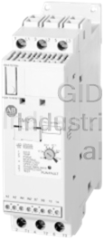
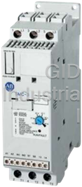
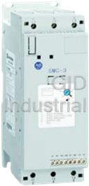
Allen Bradley 150-C85NBD SMC-3 SmartMotor Controller
Part Number
150-C85NBD
Price
Request Quote
Manufacturer
ALLEN-BRADLEY
Lead Time
Request Quote
Category
Motors
Specifications
AC Input
460 volts
Axes
1.0
Continuous Current
25 to 60 amps
Features
Soft Start
Frequency
50 Hz; 60 Hz
Phase
Single Phase
Features
- 1…480 A Range
- Built-In Electronic Motor Overload Protection
- Built-in overload relay and built-in SCR bypass contactor on all three phases
- Built-In SCR/Run Bypass
- Compact, simple to use motor controller
- Delta Compatibility
- Designed to operate 3-phase motors
- Fan included in units above 18.5kWControl voltage: 110/240V AC or 24V DC
- Modes of operation include soft start, soft stop, current limit start and kick start
- These units can be used in the inside of the delta loop with a current range 1.73 x higher
Datasheet

Extracted Text
Bulletin 150 Smart Motor Controllers — SMC-3™ Overview/Modes of Operation Bulletin 150 — Smart Motor Controllers — SMC-3™ Smart Table of Contents Motor Controller Cat. No. Explanation ............... 13 The SMC-3™ is a compact, simple to use, solid-state motor controller designed to operate 3-phase motors. It features a built-in overload relay and a built-in SCR bypass Product Selection..................... 14 contactor on all three phases, allowing a smaller footprint than other soft starters on Typical Wiring Diagrams ........ 16 the market. This product is designed for many applications, including compressors, chillers, pumps, conveyors, and crushers. Modes of operation for the controller are as Specifications............................. 18 follows: Approximate Dimensions ...... 22 y Soft Start Enclosed Options ..................... 24 y Current Limit Start Accessories (SMC-3 and y Kick Start SMC-Delta) ................................. 25 y Soft Stop y Coast-to-Rest The controllers are available in ten sizes: 3, 9, 16, 19, 25, 30, 37, 43, 60, and 85 A. They offer two voltage ranges: 200…480V AC and 200…600V AC. All voltage ranges will operate at either 50 or 60 Hz. y 1…85 A Range y Built-In Electronic Motor Overload Protection y Built-In SCR/Run Bypass Standards Compliance/Approvals y UL 508 y CSA C22.2 No. 14 y EN/IEC 60947-4-2 y cULus Listed (Open Type) (File No. E96956) y CE Marked (Open Type) per EMC Directive and Low Voltage Directive Modes of Operation Soft Start This method has the most general application. The motor is raised from an initial torque value to full voltage. This initial torque can be adjusted to 15%, 25%, 35%, or 65% of locked rotor torque. The motor voltage is gradually increased during the acceleration ramp time, which can be adjusted from 2, 5, 10, 15, 20, 25, or 30 s. (3…37 A, 2…15 s only) Current Limit Start This starting mode is used when it is necessary to limit the maximum starting current. It can be adjusted to 150%, 250%, 350%, or 450% of full load amps. Start times are selectable from 2, 5, 10, 15, 20, 25, or 30 s. (3…37 A, 2…15 s only) Selectable Kick Start A kickstart, or boost, at the beginning of the start mode is intended to provide a current pulse of 450% of full load current. The kickstart time is adjustable from 0.5…1.5 seconds. This allows the motor to develop additional torque during starting for loads which may need a boost to get initial shaft rotation. Visit our website: www.ab.com/catalogs 11 Bulletin 150 Smart Motor Controllers — SMC-3™ Modes of Operation/Features Modes of Operation, Continued Soft Stop The Soft Stop function can be used with applications that require an extended coast to rest. When enabled, the voltage ramp down time can be selected to one, two, or three times the starting time. The motor will stop when the motor voltage drops to a point where the load torque is greater than the motor torque. Description of Features Electronic Motor Overload Protection Phase Imbalance The SMC-3 controller incorporates, as standard, electronic motor The unit monitors for imbalance between phase currents. To prevent overload protection. This motor overload protection is accomplished motor damage, the unit will trip if the phase imbalance exceeds electronically with the use of current transformers on each of the specified limits and a fault will be indicated on the LED. three phases. The controller’s overload protection is programmable, providing the user with flexibility. The overload trip class selection Push to Test consists of either OFF, 10, 15, or 20. The trip current is easily The unit with control wiring can be tested for fault conditions by selected by adjusting the rotary potentiometer to the motor full load using the Push to Test function. Hold down the Reset button for 5 current rating. Trip reset is selectable to either automatic or manual seconds to activate the fault Aux (97, 98) and shut down the SMC-3. mode. To clear, either push the Reset button or cycle control power to the Note: Trip rating is 120% of dial setting. device. Over-temperature Shorted SCR The SMC-3 monitors the SCR temperature by means of internal Prior to every start and during starting, the unit will check all SCRs thermistors. When the power poles maximum rated temperature is for shorts and unit load connections to the motor. If there is a reached, the microcomputer switches off the SMC and a TEMP fault shorted SCR in the SMC-3 and/or open load, the start will be is indicated via LED. aborted and a shorted SCR or open load fault will be indicated. This prevents damage from phase imbalance. Phase Reversal Protection When enabled via a DIP switch, 3-phase input power will be verified LED Description (Number of Flashes) before starting. If input power phasing is detected to be incorrect, 1. Overload the start will be aborted and a fault indicated. 2. Overtemperature 3. Phase Reversal Phase Loss/Open Load 4. Phase Loss/Open Load The unit will not attempt a start if there is a single-phase condition 5. Phase Imbalance on the line. This protects from motor burnout during single-phase 6. Shorted SCR starting. 7. Test 12 Visit our website: www.ab.com/catalogs Bulletin 150 Smart Motor Controllers — SMC-3™ Cat. No. Explanation Cat. No. Explanation Open and Non-Combination Combination 152H – C 30 F BD 43 – 8L 150 – C 30 F B D – 8L ab c d e f g ab c d e f g a a Bulletin Number Bulletin Number Code Description Code Description 152H Solid-State Controller with Fusible Disconnect 150 Solid-State Controller 153H Solid-State Controller with Circuit Breaker b b Controller Type Controller Type Code Description Code Description C SMC-3 C SMC-3 c c Ampere Ratings Ampere Ratings Code Description Code Description 33 A 33 A 99 A 99 A 16 16 A 16 16 A 19 19 A 19 19 A 25 25 A 25 25 A 30 30 A 30 30 A 37 37 A 37 37 A 43 43 A 43 43 A 60 60 A 60 60 A 85 85 A 85 85 A d d Enclosure Type Enclosure Type Code Description Code Description F IP65 (NEMA 4/12) N Open F IP65 (NEMA 4/12) e Input Line Voltage e Open Type Input Line Voltage Code Description Open Type HD 200…208V AC, 3-Phase, 50/60 Hz Code Description AD 230V AC, 3-Phase, 50/60 Hz B 200…460V AC, 3-Phase, 50/60 Hz BD 400…460V AC, 3-Phase, 50/60 Hz C 200…600V AC, 3-Phase, 50/60 Hz CD 500…575V AC, 3-Phase, 50/60 Hz Non-Combination Enclosed Only H 200…208V AC, 3-Phase, 50/60 Hz f A 230V AC, 3-Phase, 50/60 Hz Horsepower B 400…460V AC, 3-Phase, 50/60 Hz Code Hp Code Hp C 500…575V AC, 3-Phase, 50/60 Hz 33 0.5 42 15 34 0.75 43 20 f 35 1 44 25 Control Voltage 36 1.5 45 30 Code Description 37 2 46 40 D 100…240V AC 38 3 47 50 R 24V AC/DC (Open Type only) 39 5 48 60 40 7.5 49 75 g 41 10 50 100 Options Code Description g 8L Line Mounted Protective Module (Enclosed Type only) Options Code Description 8L Line Mounted Protective Module (Enclosed Type only) Visit our website: www.ab.com/catalogs 13 Bulletin 150 Smart Motor Controllers — SMC-3™ Product Selection Open Type and Non-Combination Enclosed (IP65, NEMA 4/12) Controllers Hp kW (0.5 = 1/2, 0.75 = 3/4, 7.5 = 7-1/2) Open Type IP65 (Type 4/12) 100…240V AC Enclosed Non- 50/60 Hz 24V AC/DC Combination Current Starting Duty Control Control Controllers 7 Rated Voltage Rating (A) [V AC] 9 350% 450% 350% 450% Cat. No. Cat. No. Cat. No. 1…3 — — 0.5 0.5 150-C3NBD 150-C3NBR 150-C3FHD 3…9 — — 0.75…2 0.75…1.5 150-C9NBD 150-C9NBR 150-C9FHD 5.3…16 — — 1.5…3 1.5…3 150-C16NBD 150-C16NBR 150-C16FHD 6.3…19 — — 1.5…5 1.5…3 150-C19NBD 150-C19NBR 150-C25FHD 9.2…27.7 — — 3…7.5 3…5 150-C25NBD 150-C25NBR 150-C25FHD 200/208 10…30 — — 3…7.5 3…5 150-C30NBD 150-C30NBR 150-C30FHD 12.3…37 — — 5…10 5…7.5 150-C37NBD 150-C37NBR 150-C37FHD 14.3…43 — — 5…10 5…10 150-C43NBD 150-C43NBR 150-C43FHD 20…60 — — 7.5…15 7.5…15 150-C60NBD 150-C60NBR 150-C60FHD 28.3…85 — — 10…25 10…25 150-C85NBD 150-C85NBR 150-C85FHD 1…3 0.55 0.37 0.5 0.5 150-C3NBD 150-C3NBR 150-C3FAD 3…9 2.2 1.5 0.75…2 0.75…2 150-C9NBD 150-C9NBR 150-C9FAD 5.3…16 4 3 1.5…5 1.5…3 150-C16NBD 150-C16NBR 150-C16FAD 6.3…19 4 4 2…5 2…3 150-C19NBD 150-C19NBR 150-C25FAD 9.2…27.7 5.5 4 3…7.5 3…5 150-C25NBD 150-C25NBR 150-C25FAD 230 10…30 7.5 5.5 5…10 5…7.5 150-C30NBD 150-C30NBR 150-C30FAD 12.3…37 7.5 7.5 5…10 5…10 150-C37NBD 150-C37NBR 150-C37FAD 14.3…43 11 7.5 5…15 5…15 150-C43NBD 150-C43NBR 150-C43FAD 20…60 15 11 7.5…20 7.5…20 150-C60NBD 150-C60NBR 150-C60FAD 28.3…85 22 18.5 15…30 15…30 150-C85NBD 150-C85NBR 150-C85FAD 1…3 1.1 0.75 0.5…1.5 0.5…1 150-C3NBD 150-C3NBR 150-C3FBD 3…9 4 3 1.5…5 1.5…3 150-C9NBD 150-C9NBR 150-C9FBD 5.3…16 7.5 5.5 5…10 5…7.5 150-C16NBD 150-C16NBR 150-C16FBD 6.3…19 7.5 5.5 5…10 5…10 150-C19NBD 150-C19NBR 150-C25FBD 9.2…27.7 11 9.5 7.5…15 7.5…10 150-C25NBD 150-C25NBR 150-C25FBD 380/400/ 415/460 10…30 15 11 7.5…20 7.5…15 150-C30NBD 150-C30NBR 150-C30FBD 12.3…37 18.5 15 10…25 10…20 150-C37NBD 150-C37NBR 150-C37FBD 14.3…43 22 15 10…30 10…30 150-C43NBD 150-C43NBR 150-C43FBD 20…60 30 22 15…40 15…40 150-C60NBD 150-C60NBR 150-C60FBD 28.3…85 45 37 25…60 25…60 150-C85NBD 150-C85NBR 150-C85FBD 1…3 1.1 0.75 0.5…1.5 0.5…1 150-C3NCD 150-C3NCR 150-C3FCD 3…9 4 3 1.5…5 1.5…3 150-C9NCD 150-C9NCR 150-C9FCD 5.3…16 7.5 5.5 5…10 5…7.5 150-C16NCD 150-C16NCR 150-C16FCD 6.3…19 7.5 5.5 5…10 5…10 150-C19NCD 150-C19NCR 150-C25FCD 8.3…25 11 9.5 7.5…15 7.5…10 150-C25NCD 150-C25NCR 150-C25FCD 500/575 10…30 15 11 7.5…20 7.5…15 150-C30NCD 150-C30NCR 150-C30FCD 12.3…37 18.5 15 10…25 10…20 150-C37NCD 150-C37NCR 150-C37FCD 14.3…43 22 15 10…30 10…30 150-C43NCD 150-C43NCR 150-C43FCD 20…60 30 22 15…40 15…40 150-C60NCD 150-C60NCR 150-C60FCD 28.3…85 45 37 25…60 25…60 150-C85NCD 150-C85NCR 150-C85FCD 9 Motor FLA rating must fall within specified current range for unit to operate properly. 7 These controllers require a separate 100…240V, 50/60 Hz single-phase control source. To add a control circuit transformer to the enclosure, add the appropriate option code to the catalog string. 14 Visit our website: www.ab.com/catalogs Bulletin 150 Smart Motor Controllers — SMC-3™ Product Selection, Continued Combination Enclosed (IP65, NEMA 4/12) Controllers with Fusible Disconnect or Circuit Breaker IP65 (Type 4/12) Enclosed Combination IP65 (Type 4/12) Enclosed Combination Controllers with Fusible Disconnect 7 Controllers with Circuit Breaker 7 Rated Voltage Current Hp [V AC] Rating (A) (0.5 = 1/2, 0.75 = 3/4, 7.5 = 7-1/2) Cat. No. Cat. No. 3 0.5 152H-C3FHD-33 153H-C3FHD-33 90.75 152H-C9FHD-34 153H-C9FHD-34 91 152H-C9FHD-35 153H-C9FHD-35 9 1.5 152H-C9FHD-36 153H-C9FHD-36 91 152H-C9FHD-35 153H-C16FHD-37 16 3 152H-C16FHD-38 153H-C16FHD-38 200/208 25 5 152H-C25FHD-39 153H-C25FHD-39 37 7.5 152H-C37FHD-40 153H-C37FHD-40 43 10 152H-C43FHD-41 153H-C43FHD-41 60 15 152H-C60FHD-42 153H-C60FHD-42 85 20 152H-C85FHD-43 153H-C85FHD-43 85 25 152H-C85FHD-44 153H-C85FHD-44 3 0.5 152H-C3FAD-33 153H-C3FAD-33 90.75 152H-C9FAD-34 153H-C9FAD-34 91 152H-C9FAD-35 153H-C9FAD-35 9 1.5 152H-C9FAD-36 153H-C9FAD-36 92 152H-C9FAD-37 153H-C9FAD-37 16 3 152H-C16FAD-38 153H-C16FAD-38 230 25 5 152H-C25FAD-39 153H-C25FAD-39 30 7.5 152H-C30FAD-40 153H-C30FAD-40 37 10 152H-C37FAD-41 153H-C37FAD-41 43 15 152H-C43FAD-42 153H-C43FAD-42 60 20 152H-C60FAD-43 153H-C60FAD-43 85 25 152H-C85FAD-44 153H-C85FAD-44 85 30 152H-C85FAD-45 153H-C85FAD-45 3 0.5 152H-C3FBD-33 153H-C3FBD-33 30.75 152H-C3FBD-34 153H-C3FBD-34 31 152H-C3FBD-35 153H-C3FBD-35 9 1.5 152H-C9FBD-36 153H-C9FBD-36 92 152H-C9FBD-37 153H-C9FBD-37 93 152H-C9FBD-38 153H-C9FBD-38 16 5 152H-C16FBD-39 153H-C16FBD-39 16 7.5 152H-C16FBD-40 153H-C16FBD-40 380/400/ 415/460 25 10 152H-C25FBD-41 153H-C25FBD-41 30 15 152H-C30FBD-42 153H-C30FBD-42 37 20 152H-C37FBD-43 153H-C37FBD-43 43 25 152H-C43FBD-44 153H-C43FBD-44 43 30 152H-C43FBD-45 153H-C43FBD-45 60 40 152H-C60FBD-46 153H-C60FBD-46 85 50 152H-C85FBD-47 153H-C85FBD-47 85 60 152H-C85FBD-48 153H-C85FBD-48 30.75 152H-C3FCD-34 153H-C3FCD-34 31 152H-C3FCD-35 153H-C3FCD-35 9 1.5 152H-C9FCD-36 153H-C9FCD-36 92 152H-C9FCD-37 153H-C9FCD-37 93 152H-C9FCD-38 153H-C9FCD-38 95 152H-C9FCD-39 153H-C9FCD-39 16 7.5 152H-C16FCD-40 153H-C16FCD-40 16 10 152H-C16FCD-41 153H-C16FCD-41 500/575 25 15 152H-C25FCD-42 153H-C25FCD-42 30 20 152H-C30FCD-43 153H-C30FCD-43 37 25 152H-C37FCD-44 153H-C37FCD-44 43 30 152H-C43FCD-45 153H-C43FCD-45 43 40 152H-C43FCD-46 153H-C43FCD-46 60 50 152H-C60FCD-47 153H-C60FCD-47 85 60 152H-C85FCD-48 153H-C85FCD-48 85 75 152H-C85FCD-49 153H-C85FCD-49 7 These controllers require a separate 100…240V, 50/60 Hz single-phase control source. To add a control circuit transformer to the enclosure, add the appropriate option code to the catalog string. Visit our website: www.ab.com/catalogs 15 Bulletin 150 Smart Motor Controllers — SMC-3™ Typical Wiring Diagrams Two-Wire Configuration IEC NEMA Three-Wire Configuration IEC NEMA 16 Visit our website: www.ab.com/catalogs Bulletin 150 Smart Motor Controllers — SMC-3™ Typical Wiring Diagrams, Continued Isolation Contactor Configuration IEC NEMA Reversing Configuration Note: Minimum Off time equals 1.0 s. IEC NEMA Visit our website: www.ab.com/catalogs 17 Bulletin 150 Smart Motor Controllers — SMC-3™ Specifications Electrical Ratings Cat. Nos. 150-… Cat. No. C3 C9 C16 C19 C25 C30 C37 C43 C60 C85 3 9 16 19 25 30 37 43 60 85 Rated operating current I (A) e Heat dissipation (W) Continuous 11 12 14 15 17 19 24 34 50 82 Rated operating voltage 200…480, 200…600V AC 50/60 Hz, 3-phase (+10%, -15%) 2 2.5…95 mm (14…3/0 AWG) 2 Cable size: 2.5…25 mm (14…4 AWG) Line Power terminals 11.3…12.4 Nm Tightening torque: 2.3…3.4 Nm (20…30 in-lbs) (100…110 in-lbs) 2 2.5…50 mm (14…1 AWG) 2 Cable size: 2.5…16 mm (14…6 AWG) Load Power terminals 11.3…12.4 Nm Tightening torque: 2.3…3.4 Nm (20…30 in-lbs) (100…110 in-lbs) 2 Cable size: 0.2…2.5 mm (24…14 AWG) Control terminals Tightening torque: 0.5…0.9 Nm (4.4…8.0 in-lbs) Maximum continuous current 3 A 9 A 16 A 19 A 25 A 30 A 37 A 43 A 60 A 85 A Overload current range (A) 1…3 3…9 5.3…16 6.3…19 9.2…27.7 10…30 12.3…37 14.3…43 20…60 28.3…85 Control Voltage Requirements 100…240V AC or 24V AC/DC 50/60 Hz Short Circuit Coordination (Max Fuse or Circuit Breaker Size) Type 1 5 kA Available Fault Current UL Class K5 Fuses UL Listed Combination (600V) 10 A 35 A 60 A 70 A 100 A 110 A 125 A 150 A — — 10 kA Available Fault Current UL Class K5 Fuses UL Listed Combination (600V) — — — — — — — — 225 A 300 A 5 kA Available Fault Current UL Class RK5 Fuses UL Listed Combination (600V) 10 A 35 A 60 A 70 A 100 A 110 A 125 A 150 A — — 10 kA Available Fault Current UL Class RK5 Fuses UL Listed Combination (600V) — — — — — — — — 225 A 300 A 5 kA Available Fault Current UL Listed Thermal Magnetic Circuit Breaker UL Listed Combination (600V) 15 A 35 A 60 A 70 A 100 A 110 A 125 A 150 A — — 10 kA Available Fault Current UL Listed Thermal Magnetic Circuit Breaker UL Listed Combination (600V) — — — — — — — — 225 A 300 A 5 kA Available Fault Current UL Listed Bulletin 140M Motor Protection C.B. UL Listed Combination (600V) C25 C25 F45 F45 F45 F45 F45 — — — Power Circuit UL/cUL IEC 200…480V AC 200…480V~ — 400V~ Rated operational voltage 200…600V AC 500V~ — 500V~ Rated insulation voltage 600V AC 500V~ Dielectric withstand 2200V AC 2500V~ 200…480V AC — 1400V 200…480V~ — 1400V Repetitive peak 200…600V AC — 1600V 500V~ — 1600V Operating frequency 50/60 Hz 50/60 Hz 1…37 A AC-53b: 3.5-15:3585 Utilization category Intermittent duty 43…85 A AC-53b: 4.5-30:3570 Number of poles Equipment designed for 3-phase only Rated impulse voltage 6 kV DV/DT protection 1000V/µs Overvoltage category III III Control Circuit UL/cUL IEC Rated operational voltage (+10%, –15%) 100…240V AC, 24V AC/DC 100…240V~, 24V AC/DC Rated insulation voltage 250V 250V~ Rated impulse voltage — 4 kV Dielectric withstand 1500V AC 2000V~ Overvoltage category — III 9 Operating frequency 50/60 Hz 50/60 Hz Input onstate voltage minimum, during start (IN1, IN2) 85V AC, 19.2V DC / 13.5V AC Input onstate current (IN1, IN2) 9.8 mA @120V AC/19.6 mA @ 240V AC, 7.3 mA @ 24V AC/DC Input offstate voltage maximum (IN1, IN2) 40V AC, 17V DC / 12V AC Input offstate current @ input offstate voltage <10 mA, <12 mA (IN1, IN2) 3…37 A 215 mA @ 120V AC / 180 mA @ 240V AC, 800 mA @ 24V DC / 660 mA @ 24V AC Control power with fan, during start 43…85 A 200 mA @ 120V AC / 100 mA @ 240V AC, 700 mA @ 24V AC/DC Control power without fan, during 3…37 A 205 mA @ 120V AC / 145 mA @ 240V AC, 705 mA @ 24V DC / 580 mA @ 24V AC start 9 Overvoltage category II, when either control or auxiliary circuit is wired to a SELV or PELV circuit. 18 Visit our website: www.ab.com/catalogs Bulletin 150 Smart Motor Controllers — SMC-3™ Specifications, Continued Auxiliary Contacts UL/cUL IEC Rated operational voltage 250V AC / 30V DC 250V~ / 30V DC Rated insulation voltage 250V 250V~ Rated impulse voltage — 4 kV Dielectric withstand 1500V AC 2000V~ Overvoltage category — III 9 Operating frequency 50/60 Hz 50/60 Hz Utilization category D300 AC15 Type of control circuit Electromagnetic relay Number of contacts 1 Type of contacts Normally Open (N.O.) TB-97, -98 Kind of current AC/DC (OVLD/Fault) Rated operational current (max.) 0.6 A @ 120V~ and 0.3 A @ 240V~ 1 A Conventional thermal current I th Make VA/break VA 432/72 Type of control circuit Electromagnetic relay Number of contacts 1 Type of contacts Normally Open (N.O.) TB-13, -14 Kind of current AC/DC (Normal/Up- to-Speed) Rated operational current (max.) 0.6 A @ 120V~ and 0.3 A @ 240V~ Conventional thermal current I 1 A th Make VA/break VA 432/72 Standard Features 2, 5, 10, or 15 s (3…85 A) Selectable start times 20, 25, or 30 s (43…85 A only) Selectable initial torque 15%, 25%, 35%, and 65% of locked rotor torque Selectable current limit 150%, 250%, 350%, and 450% of full load current Selectable kick start — 450% FLA 0, 0.5, 1.0, or 1.5 s Selectable soft stop Off, 100%, 200%, or 300% of the start time setting when wired 1…37 A 0.86 (1.9) Weight — kg (lbs) 43…85 A 2.25 (5) Mechanical Design Specifications/Test Requirements 1.0 G peak, 0.152 mm (0.006 in.) displacement Resistance Operational to vibration Non-operational 2.5 G peak, 0.381 mm (0.015 in.) displacement Operational 15 G Resistance to shock Non-operational 30 G Environmental 0…50 °C (32…122 °F) (open) Operating temperature 0…40 °C (32…104 °F) (enclosed) Storage temperature -25…85 °C (-13…185 °F) Altitude 2000 m (6560 ft) Humidity 5…95% (non-condensing) Pollution degree 2 Type of Protection IP2X Other UL/cUL IEC EMC Conducted radio frequency emissions — Class A emission Radiated emissions — Class A levels Electrostatic discharge 4 kV contact and 8kV air discharge EMC Radio frequency electromagnetic field — Per IEC 60947-4-2 immunity Fast transient — Per IEC 60947-4-2 levels Surge transient — Per IEC 60947-4-2 Wiring Diagrams Can be found in pub. 150-SG006C-EN-P or at www.ab.com/catalogs 9 Overvoltage category II, when either control or auxiliary circuit is wired to a SELV or PELV circuit. Visit our website: www.ab.com/catalogs 19 Bulletin 150 Smart Motor Controllers — SMC-3™ Specifications, Continued Side-Mount Auxiliary Contact Specifications UL/cUL IEC Rated Operational Voltage 250V AC/30V DC 250V AC/30V DC Rated Insulation Voltage 250V 250V AC Rated Impulse Voltage — 4 kV Dielectric Withstand 1500V AC 2000V AC Overvoltage Category — III 9 Operating Frequency 50/60 Hz 50/60 Hz Utilization Category C300/R150 AC-15/DC-13 Type of Control Circuit Electromagnetic Relay No. of Contacts 1 TB-23, -24 Type of Contact Normally Open (N.O.) (Normal/Up-to-Speed) TB-33, -34 Current AC/DC (Normal/Up-to-Speed) Rated Operational Current (max.) 1.5 A @ 120V AC, 0.75A @ 240V AC, 1.17 A @ 24V DC Conventional Thermal Current I 2.5 A th Make VA/Break VA 1800/180V AC, 28V DC Utilization Category B300/R300 AC-15/DC-13 Type of Control Circuit Electromagnetic Relay No. of Contacts 1 Type of Contact Normally Closed (N.C.) TB-11, -12 (Normal/Up-to-Speed) Current AC/DC Rated Operational Current (max.) 3 A @ 120V AC, 1.5A @ 240V AC, 1.17 A @ 24V DC Conventional Thermal Current I 5 A th Make VA/Break VA 3600/360 V AC, 28V DC 9 Overvoltage category II when either control or auxiliary circuit is wired to a SELV or PELV circuit. 20 Visit our website: www.ab.com/catalogs Bulletin 150 Smart Motor Controllers — SMC-3™ Trip and Starts per Hour Curves SMC-3 Overload Trip Curves Trip Class 10 Trip Class 15 Trip Class 20 Starts per Hour Curves SMC-3 Starts per hour (14-85A) 40C,100% Duty Cycle, 20sec, 350% (with standard fan) 200 180 160 140 120 100 80 60 40 150-C43 20 150-C60 0 150-C85 0 1020 30405060 708090 Current (amps) Visit our website: www.ab.com/catalogs 21 Starts Bulletin 150 Smart Motor Controllers — SMC-3™ Approximate Dimensions Dimensions in millimeters (inches). Dimensions are not intended to be used for manufacturing purposes. All dimensions are subject to change. Open Type Mounting Controller A B C D E F G Hole Size 1…37 A 44.8 (1-49/64) 139.7 (5-1/2) 100 (4-21/64) 35 (1-3/8) 132 (5-13/64) 46.4 (1.81) 2 (1/16) 4.6 (0.18) 43…85 A 72 (2.83) 206 (8.11) 130 (5.12) 55 (2.17) 198 (7.8) 102 (4.02 2 (1/16) 5.3 (0.21) Minimum Enclosure Size Controller A Width B Height C Depth Fan Requirements 1…37 A 224 (9) 305 (12) 152 (6) none 43…85 A 406 (16) 305 (12) 203 (8) none 22 Visit our website: www.ab.com/catalogs Bulletin 150 Smart Motor Controllers — SMC-3™ Approximate Dimensions, Continued Enclosed Type Controllers IP65 (Type 4/12) Controller Rating (A) Disconnect Rating (A) B Height A Width C Depth Non-Combination Controller 3 — 305 (12) 305 (12) 152 (6) 9 — 305 (12) 305 (12) 152 (6) 16 — 305 (12) 305 (12) 152 (6) 25 — 305 (12) 305 (12) 152 (6) 30 — 305 (12) 305 (12) 152 (6) 37 — 305 (12) 305 (12) 152 (6) 43 — 356 (14) 406 (16) 203 (8) 60 — 356 (14) 406 (16) 203 (8) 85 — 356 (14) 406 (16) 203 (8) Combination Controllers with Fusible Disconnect 3 30 A/J 356 (14) 406 (16) 203 (8) 9 30 A/J 356 (14) 406 (16) 203 (8) 16 30 A/J 356 (14) 406 (16) 203 (8) 25 30 A/J 356 (14) 406 (16) 203 (8) 30 60 A/J 356 (14) 406 (16) 203 (8) 37 60 A/J 356 (14) 406 (16) 203 (8) 43 60 A/J 356 (14) 406 (16) 203 (8) 60 100 A/J 610 (24) 406 (16) 229 (9) 859 100 A/J 610 (24) 406 (16) 229 (9) 857 100 A/J 762 (30) 610 (24) 305 (12) Combination Controllers with Circuit Breaker 3 15 A 356 (14) 406 (16) 203 (8) 9 15 A 356 (14) 406 (16) 203 (8) 16 20 A 356 (14) 406 (16) 203 (8) 25 30 A 356 (14) 406 (16) 203 (8) 30 40 A 356 (14) 406 (16) 203 (8) 37 50 A 356 (14) 406 (16) 203 (8) 43 80 A 610 (24) 406 (16) 229 (9) 60 100 A 610 (24) 406 (16) 229 (9) 85 125 A 610 (24) 406 (16) 229 (9) 9 Dimensions for FHD-43, FAD-44, FBD-47, and FCD-48. 7 Dimensions for FHD-44, FAD-45, FBD-48, and FCD-49 Visit our website: www.ab.com/catalogs 23 Bulletin 150 Smart Motor Controllers — SMC-3™ Enclosed Options Enclosed Options Cat. No. Option Description Modification Push Buttons Start-Stop Push Button -1 Selector Switch Hand-Off-Auto Selector Switch -3 Pilot Light Transformer Pilot Light (Red Lens) -4R Control Circuit Transformer Control Circuit Transformer (fused primary and secondary) -6P 480V Line Side Protective Module 3…85 A -8L 600V Line Side Protective Module 3…85 A 480V Load Side Protective Module 43…85 A Protective Module -8M 600V Load Side Protective Module 43…85 A 480V Both Line and Load Side Protective Module 43…85 A -8B 600V Both Line and Load Side Protective Module 43…85 A 1 N.O. auxiliary contact for 3…85 A units -90 Auxiliary Contacts 2 N.O. auxiliary contacts for 3…85 A units -900 1 N.O. and 1 N.C. auxiliary contacts for 3…85 A units -901 N.O. disconnect auxiliary mounted on the operating mechanism -98 Disconnect Auxiliary N.C. disconnect auxiliary mounted on the operating mechanism -99 24 Visit our website: www.ab.com/catalogs Bulletin 150 Smart Motor Controllers — SMC-3™ Accessories - Field Modifications Accessories (SMC-3 and SMC-Delta) Description N.O. N.C. Connection Diagram Cat. No. 10 150-CA10 Auxiliary Contact Blocks for Side Mounting with 20 150-CA20 Sequence Terminal Designations 1- and 2-pole 01 150-CA01 Quick and easy mounting without tools 150-CA11 One block per device only 11 (Form C) Description For Use With Pkg. Qty. Cat. No. 150-C3…37/150-D3…64 150-CF64 Fan 1 Field installed. 150-C43…85/150-D74…147 150-CF147 Connects 140M-C to 1 150-CC25 150-C3…25/150-D3…25 Connecting modules to 140M Electrical interconnection between SMC-Delta/SMC-3 Connects 140M-D to 1 150-CD25 and 140M. 150-C3…25/150-D3…25 Motor protector and SMC must be mounted separately. Connects 140M-F to 1 150-CF45 150-C3…37/150-D3…32 Connects 100-C09…23 to Connecting modules to 100C 1 150-CI23 150-C3…19/150-D3…20 Electrical interconnection between SMC-Delta/SMC-3 and 100C. Connects 100-C30…37 to 1 150-CI37 Contactor and SMC must be mounted separately. 150-C3…37/150-D3…32 Description For Use With Cat. No. 150-C3…37NB or 150-D3…64NB 150-C84 480V Protective Module 150-C43…85NB or 150-D74…147NB 150-C84P 150-C3…37NC or 150-D3…64NC 150-C86 600V Protective Module 150-C43…85NC or 150-D74…147NC 150-C86P Description For Use With Pkg. Qty. Cat. No. Marking Tag Sheet 10 sheets with 160 perforated paper labels each, 6 x 17 150-C, 150-D 10 100-FMP mm To be used with a transparent cover Transparent Cover 100 each 150-C, 150-D 100 100-FMC To be used with marking tag sheets Remote Reset Solenoid for remote reset of electronic 193-ER1⊗ 150-C, 150-D 1 overload ⊗ Voltage Suffix Code Available Coil Voltages 12… 600V 50 Hz/12…600V 60 Hz Standard Coil Voltages Voltage 24 48 110 115 120 220 220…230 240 50 Hz J — D — — A F — 60 Hz J — — — D — — A DC Z24 Z48 — Z01 — — — — Surcharge for special voltages up to 20 pcs. (no surcharge for quantities greater than 20 pcs.) Visit our website: www.ab.com/catalogs 25 Bulletin 150 Smart Motor Controllers - SMC-Delta™ Overview/Modes of Operation/Description of Features Bulletin 150 — Smart Motor Controllers — SMC-Delta™ Table of Contents Smart Motor Controller Cat. No. Identification............ 27 The SMC-Delta™ is a compact, simple to use, solid-state motor controller designed to operate 3-phase star-delta motors wired on an inside-the-delta configuration. This Product Selection.................... 28 star-delta replacer is ideally designed for 6-lead motor applications. It features a built- Typical Wiring Diagrams ....... 29 in overload relay and a built-in silicon controlled rectifier (SCR) bypass contactor on all three phases, allowing a smaller footprint than traditional methods of starting. This Specifications............................ 31 product is designed for many applications including compressors, chillers, pumps, Approximate Dimensions ..... 34 conveyors, and crushers. Modes of operation for the controller are as follows: Accessories (SMC-3 and y Current Limit Start SMC-Delta)................................. 25 y Coast to Rest The controllers are available in 11 sizes: 3, 9, 16, 20, 25, 32, 51, 64, 74, 104, and 147 A. They offer two voltage ranges: 200…460V AC and 200…575V AC. All voltage ranges will operate at either 50 or 60 Hz. y 1…147 A Range y Built-in Motor Overload Protection y Built-in SCR Bypass Standards Compliance/Approvals y UL 508 y CSA C22.2 No. 14 y EN/IEC 60947-4-2 y cULus Listed (Open Type) (File No. E96956) y CE Marked (Open Type) per EMC Directive and Low Voltage Directive Mode of Operation Current Limit Start This starting mode is used when it is necessary to limit the maximum starting current. It can be adjusted for 150%, 250%, 300%, or 350% of full load amps. Start times are selectable from 2, 5, 10, or 15 s. Description of Protection Features Overload Protection Shorted SCR The SMC-Delta has a built-in overload feature. Trip class selection Prior to every start, the unit will check all SCRs for shorts and unit consists of either OFF, 10, 15, or 20. It provides improved protection load connections to the motor. If there is a shorted SCR in the against the damage caused to motors when operated under phase SMC-Delta, the start will be aborted and a shorted SCR fault will be loss conditions. Trip reset is selectable to either automatic or indicated. This prevents damage from phase imbalance. manual mode. As standard, it includes a manually generated trip Push to Test function, LED indication, and N.O. alarm contact. The unit with control wiring can be tested for fault conditions by Over-temperature using the Push to Test function. Hold down the Reset button for 5 seconds to activate the fault Aux (97, 98) and shut down the SMC- The SMC-Delta monitors the SCR temperature by means of internal 3. thermistors. When the power poles maximum rated temperature is reached, the microcomputer switches off the SMC and a TEMP fault is indicated via LED. LED Description (Number of Flashes) 1. Overload Phase Loss/Open Load 2. Overtemperature The unit will not attempt a start if there is a single-phase condition 3. Not Used on the line. This protects from motor burnout during single-phase 4. Phase Loss/Open Load starting. 5. Phase Imbalance 6. Shorted SCR 7. Test Phase Imbalance The unit monitors for imbalance between phase currents. To prevent motor damage, the unit will trip if the phase imbalance exceeds specified limits and a fault will be indicated on the LED. 26 Visit our website: www.ab.com/catalogs Bulletin 150 Smart Motor Controllers - SMC-Delta™ Cat. No. Identification Χατ. Νο. Ιδεντιφιχατιον Open Type 150 – D 32 N B D ab c d e f a Bulletin Number Code Description 150 Solid-State Controller b Controller Type Code Description D SMC-Delta c Ampere Ratings Code Description 33 A 99 A 16 16 A 20 20 A 25 25 A 32 32 A 51 51 A 64 64 A 74 74 A 104 104 A 147 147 A d Enclosure Type Code Description N Open e Input Line Voltage Open Type Code Description B 200…460V AC, 3-Phase, 50/60 Hz C 200…575V AC, 3-Phase, 50/60 Hz f Control Voltage Code Description D 100…240V AC R 24V AC/DC Visit our website: www.ab.com/catalogs 27 Bulletin 150 Smart Motor Controllers - SMC-Delta™ Product Selection Product Selection Open Type Controllers 100…240V AC, 50/60 Hz 24V AC/DC Control Control Current Rated Voltage Rating (A) [V AC] 9 kW Hp Cat. No. Cat. No. 1…3 — 0.5 150-D3NBD 150-D3NBR 3…9 — 0.75…2 150-D9NBD 150-D9NBR 5.3…16 — 1.5…3 150-D16NBD 150-D16NBR 6.7…20 — 2…5 150-D20NBD 150-D20NBR 9.2…27.7 — 3…7.5 150-D25NBD 150-D25NBR 200/208 10.6…32.9 — 3…10 150-D32NBD 150-D32NBR 17.3…51.9 — 5…15 150-D51NBD 150-D51NBR 21.3…64 — 7.5…20 150-D64NBD 150-D64NBR 24.7…74 — 7.5…20 150-D74NBD 150-D74NBR 34.7…104 — 15…30 150-D104NBD 150-D104NBR 49…147 — 15…40 150-D147NBD 150-D147NBR 1…3 0.55 0.5 150-D3NBD 150-D3NBR 3…9 2.2 0.75…2 150-D9NBD 150-D9NBR 5.3…16 4 1.5…5 150-D16NBD 150-D16NBR 6.7…20 5.5 2…5 150-D20NBD 150-D20NBR 9.2…27.7 5.5 3…7.5 150-D25NBD 150-D25NBR 230 10.6…32.9 7.5 5…10 150-D32NBD 150-D32NBR 17.3…51.9 15 7.5…15 150-D51NBD 150-D51NBR 21.3…64 18.5 7.5…20 150-D64NBD 150-D64NBR 24.7…74 22 7.5…25 150-D74NBD 150-D74NBR 34.7…104 30 15…40 150-D104NBD 150-D104NBR 49…147 45 20…50 150-D147NBD 150-D147NBR 1…3 1.1 0.5…1.5 150-D3NBD 150-D3NBR 3…9 4 1.5…5 150-D9NBD 150-D9NBR 5.3…16 7.5 5…10 150-D16NBD 150-D16NBR 6.7…20 7.5 5…10 150-D20NBD 150-D20NBR 9.2…27.7 11 7.5…15 150-D25NBD 150-D25NBR 380/400/ 10.6…32.9 15 7.5…20 150-D32NBD 150-D32NBR 415/460 17.3…51.9 22 15…30 150-D51NBD 150-D51NBR 21.3…64 30 20…40 150-D64NBD 150-D64NBR 24.7…74 37 15…50 150-D74NBD 150-D74NBR 34.7…104 55 25…75 150-D104NBD 150-D104NBR 49…147 75 40…100 150-D147NBD 150-D147NBR 1…3 0.55 0.5 150-D3NCD 150-D3NCR 3…9 2.2 0.75…2 150-D9NCD 150-D9NCR 5.3…16 4 1.5…3 150-D16NCD 150-D16NCR 6.7…20 5.5 2…5 150-D20NCD 150-D20NCR 9.2…25 5.5 3…7.5 150-D25NCD 150-D25NCR 500/575 10.6…32 7.5 3…10 150-D32NCD 150-D32NCR 17…51 15 5…15 150-D51NCD 150-D51NCR 21.3…64 18.5 7.5…20 150-D64NCD 150-D64NCR 24.7…74 22 7.5…20 150-D74NCD 150-D74NCR 34.7…104 30 15…30 150-D104NCD 150-D104NCR 49…147 45 15…40 150-D147NCD 150-D147NCR 9 Motor FLA must fall within the current range of the device. 28 Visit our website: www.ab.com/catalogs Bulletin 150 Smart Motor Controllers - SMC-Delta™ Typical Wiring Diagrams Two-Wire Configuration IEC NEMA Three-Wire Configuration NEMA IEC Visit our website: www.ab.com/catalogs 29 Bulletin 150 Smart Motor Controllers - SMC-Delta™ Typical Wiring Diagrams, Continued Isolation Contactor Configuration IEC NEMA Reversing Configuration Note: Minimum Off time equals 1.0 s. NEMA IEC 30 Visit our website: www.ab.com/catalogs Bulletin 150 Smart Motor Controllers - SMC-Delta™ Specifications Electrical Ratings Cat. Nos. 150-… Cat. No. D3 D9 D16 D20 D25 D32 D51 D64 D74 D104 D147 Rated operating current I (A) 3 9 16 20 25 32 51 64 74 104 147 e Heat Continuous 7 7 7 8 8 10 14 19 27 42 74 dissipation (W) Rated operating voltage 200…480, 500…600V AC 50/60 Hz, 3-phase (+10%, -15%) 2 2 Cable size: 2.5…25 mm (14…4 AWG) 2.5…95 mm (14…3/0 AWG) Line Power Tightening terminals 2.3…3.4 Nm (20…30 in-lbs) 11.3…12.4 Nm (100…110 in-lbs) torque: 2 2 Cable size: 2.5…16 mm (14…6 AWG) 2.5…50 mm (14…1 AWG) Load Power Tightening terminals 2.3…3.4 Nm (20…30 in-lbs) 11.3…12.4 Nm (100…110 in-lbs) torque: 2 Cable size: 0.2…2.5 mm (24…14 AWG) Control Tightening terminals 0.5…0.9 Nm (4.4…8.0 in-lbs) torque: Maximum continuous current 3 A 9 A 16 A 20 A 25 A 32 A 51 A 64 A 74 A 104 A 147 A Maximum delta amps 1.74 5.2 9.3 11.6 14.5 17.4 29.6 36.5 42.8 60.1 85 Overload current range (A) 1…3 3…9 5.3…16 6.7…20 9.2…27.7 10.6…32.9 17.3…51.9 21.3…64 24.7…74 34.7…104 49…147 Control Voltage Requirements 100…240V AC or 24V AC/DC 50/60 Hz Short Circuit Coordination (Max Fuse or Circuit Breaker Size) Type 1 UL Class K5 Fuses 5 kA Available Fault Current UL Listed Combination (600V) 10 A 35 A 60 A 80 A 100 A 125 A — — — — — UL Class K5 Fuses 10 kA Available Fault Current UL Listed Combination (600V) — — — — — — 200 A 250 A 250 A 400 A 400 A UL Class RK5 Fuses 5 kA Available Fault Current UL Listed Combination (600V) 10 A 35 A 60 A 80 A 100 A 125 A — — — — — UL Class RK5 Fuses 10 kA Available Fault Current UL Listed Combination (600V) — — — — — — 200 A 250 A 250 A 400 A 400 A UL Listed Thermal Magnetic 5 kA Available Fault Current Circuit Breaker UL Listed Combination (600V) 10 A 35 A 60 A 80 A 100 A 125 A — — — — — UL Listed Thermal Magnetic 10 kA Available Fault Current Circuit Breaker UL Listed Combination (600V) — — — — — — 200 A 250 A 250 A 300 A 400 A UL Listed Bulletin 140M Motor 5 kA Available Fault Current Protection C.B. UL Listed Combination (600V) C25 C25 C25 F45 F45 F45 — — — — — Power Circuit UL/cUL IEC 200…480V AC 200…480V~ — 400V~ Rated operational voltage 500…600V AC 500V~ — 500V~ Rated insulation voltage 600V AC 500V~ Dielectric withstand 2200V AC 2500V~ 200…480V AC — 1400V 200…480V~ — 1400V Repetitive peak 500…600V AC — 1600V 500V~ — 1600V Operating frequency 50/60 Hz 50/60 Hz 1…64 A AC-53b: 3.5-15:3585 Utilization Intermittent duty category 74…147 A AC-53b: 3.5-30:3570 Number of poles Equipment designed for 3-phase only Rated impulse voltage 6 kV 1000 V/µs DV/DT protection Overvoltage Category III III Environmental 0…50 °C (32…122 °F) (open) Operating temperature 0…40 °C (32…104 °F) (enclosed) Storage temperature -25…85 °C (-13…185 °F) Altitude 2000 m (6560 ft) Humidity 5…95% (non-condensing) Pollution degree 2 Type of Protection IP2X Visit our website: www.ab.com/catalogs 31 Bulletin 150 Smart Motor Controllers - SMC-Delta™ Specifications, Continued Control Circuit UL/cUL IEC Rated operational voltage (+10%, –15%) 100…240V AC, 24V AC/DC 100…240V~, 24V AC/DC Rated insulation voltage 250V 250V~ Rated impulse voltage — 4 kV Dielectric withstand 1500V AC 2000V~ Overvoltage category — III 9 Operating frequency 50/60 Hz 50/60 Hz Input onstate voltage minimum, during start (A1, 1) 85V AC, 19.2V DC/13.5V AC 3…64 A 195 mA @ 120V AC/140 mA @ 240V AC, 790mA @24V DC/650 mA @24V AC Input onstate current, during start with fan (A1, 1) 74…147 A 200 mA @ 120V AC/100 mA @ 240V AC, 700 mA @24V AC/DC Input offstate voltage maximum (A1, 1) 30V AC, 17V DC/12V AC Input offstate current @ input offstate voltage (A1, 1) <2 mA 3…64 A 195 mA @ 120V AC / 140 mA @ 240V AC, 790 mA @ 24V DC / 650 mA @ 24V AC Control power with fan, during start 74…147 A 200 mA @ 120V AC/100 mA @ 240V AC, 700 mA @24V AC/DC Control power without fan, during start 185 mA @ 120V AC/125 mA @ 240V AC, 695 mA @24V DC/ 570 mA @ 24V AC Auxiliary Contact UL/cUL IEC Rated operational voltage 250V AC/30V DC 250V~/30V DC Rated insulation voltage 250V 250V~ Rated impulse voltage — 4 kV Dielectric withstand 1500V AC 2000V~ Overvoltage category — III 9 Operating frequency 50/60 Hz 50/60 Hz Utilization category D300 AC15 Type of control circuit Electromagnetic relay Number of contacts 1 Type of contacts Normally Open (N.O.) TB-97, -98 Kind of current AC/DC (OVLD/Fault) Rated operational current (max.) 0.6 A @ 120V~ and 0.3 A @ 240V~ Conventional thermal current Ith 1 A Make VA/break VA 432/72 Standard Features Start times 2, 5, 10, or 15 s Selectable current limit 150%, 250%, 300%, and 350% of full load current 1…64 A 0.86 (1.9) Weight — kg (lbs) 74…147 A 2.25 (5) Mechanical Design Specifications/Test Requirements Operational 1.0 G peak, 0.152 mm (0.006 in.) displacement Resistance to vibration Non-operational 2.5 G peak, 0.381 mm (0.015 in.) displacement Operational 15 G Resistance to shock Non-operational 30 G Other UL/cUL IEC EMC Conducted radio frequency emissions — Class A emission Radiated emissions — Class A levels Electrostatic discharge 4 kV contact and 8kV air discharge EMC Radio frequency electromagnetic field — Per IEC 60947-4-2 immunity Fast transient — Per IEC 60947-4-2 levels Surge transient — Per IEC 60947-4-2 Wiring Diagrams Can be found in pub. 150-SG006C-EN-P or at www.ab.com/catalogs 9 Overvoltage category II, when either control or auxiliary circuit is wired to a SELV or PELV circuit. 32 Visit our website: www.ab.com/catalogs Bulletin 150 Smart Motor Controllers - SMC-Delta™ Trip and Starts per Hour Curves SMC-Delta Overload Trip Curves Trip Class 10 Trip Class 15 Trip Class 20 Starts per Hour Curves SMC-Delta Starts per hour (24-147A) 40C,100% Duty Cycle, 20sec, 350% with fan 200 180 160 140 120 100 80 60 40 20 0 150-D74 0 30 60 90 120 150 150-D60 Current (amps) 150-D147 Visit our website: www.ab.com/catalogs 33 Starts Bulletin 150 Smart Motor Controllers - SMC-Delta™ Approximate Dimensions Αππροξιµατε ∆ιµενσιονσ Dimensions in millimeters (inches). Dimensions are not intended to be used for manufacturing purposes. All dimensions are subject to change. Open Type Mounting Controller A B C D E F G Hole Size 1…64 A 44.8 (1-49/64) 139.7 (5-1/2) 100 (4-21/64) 35 (1-3/8) 132 (5-13/64) 46.4 (1.81) 2 (1/16) 4.6 (0.18) 74…147 A 72 (2.83) 206 (8.11) 130 (5.12) 55 (2.17) 198 (7.8) 102 (4.02 2 (1/16) 5.3 (0.21) Minimum Enclosure Size Controller A Width B Height C Depth Fan Requirements 1…64 A 224 (9) 305 (12) 152 (6) none 74…147 A 406 (16) 305 (12) 203 (8) none 34 Visit our website: www.ab.com/catalogs
Frequently asked questions
How does Industrial Trading differ from its competitors?

Is there a warranty for the 150-C85NBD?
Which carrier will Industrial Trading use to ship my parts?
Can I buy parts from Industrial Trading if I am outside the USA?
Which payment methods does Industrial Trading accept?
Why buy from GID?

Quality
We are industry veterans who take pride in our work

Protection
Avoid the dangers of risky trading in the gray market

Access
Our network of suppliers is ready and at your disposal

Savings
Maintain legacy systems to prevent costly downtime

Speed
Time is of the essence, and we are respectful of yours
Related Products

Allen Bradley 064303003 Motors - Servo Motor
Allen Bradley 150-C108NBD Line-Connected Motor, 100…240V AC, 50/60 Hz Control Power, 200/208VAC Rate...
Allen Bradley 150-C135NBD Line-Connected Motor, 100…240V AC, 50/60 Hz Control Power, 200/208VAC Rate...
Allen Bradley 150-C25NBR Line-Connected Motor, 24V AC/DC Control Power, 200/208VAC Rated Voltage
Allen Bradley 150-C37NBR Line-Connected Motor, 24V AC/DC Control Power, 200/208VAC Rated Voltage
Allen Bradley 150-C43NBD Line-Connected Motor, 100…240V AC, 50/60 Hz Control Power, 200/208VAC Rated...
Request a Quote

The quote request has been received
Close

Facing challenges or have inquiries? Feel free to contact us!
Call Us +1-469-283-2440
What they say about us
FANTASTIC RESOURCE
One of our top priorities is maintaining our business with precision, and we are constantly looking for affiliates that can help us achieve our goal. With the aid of GID Industrial, our obsolete product management has never been more efficient. They have been a great resource to our company, and have quickly become a go-to supplier on our list!
Bucher Emhart Glass
EXCELLENT SERVICE
With our strict fundamentals and high expectations, we were surprised when we came across GID Industrial and their competitive pricing. When we approached them with our issue, they were incredibly confident in being able to provide us with a seamless solution at the best price for us. GID Industrial quickly understood our needs and provided us with excellent service, as well as fully tested product to ensure what we received would be the right fit for our company.
Fuji
HARD TO FIND A BETTER PROVIDER
Our company provides services to aid in the manufacture of technological products, such as semiconductors and flat panel displays, and often searching for distributors of obsolete product we require can waste time and money. Finding GID Industrial proved to be a great asset to our company, with cost effective solutions and superior knowledge on all of their materials, it’d be hard to find a better provider of obsolete or hard to find products.
Applied Materials
CONSISTENTLY DELIVERS QUALITY SOLUTIONS
Over the years, the equipment used in our company becomes discontinued, but they’re still of great use to us and our customers. Once these products are no longer available through the manufacturer, finding a reliable, quick supplier is a necessity, and luckily for us, GID Industrial has provided the most trustworthy, quality solutions to our obsolete component needs.
Nidec Vamco
TERRIFIC RESOURCE
This company has been a terrific help to us (I work for Trican Well Service) in sourcing the Micron Ram Memory we needed for our Siemens computers. Great service! And great pricing! I know when the product is shipping and when it will arrive, all the way through the ordering process.
Trican Well Service
GO TO SOURCE
When I can't find an obsolete part, I first call GID and they'll come up with my parts every time. Great customer service and follow up as well. Scott emails me from time to time to touch base and see if we're having trouble finding something.....which is often with our 25 yr old equipment.
ConAgra Foods