

 Manufacturers
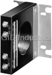
ALLEN-BRADLEY 1409N2
Description
Allen Bradley 1409N2 Arcing Ground Fault Sensor
Part Number
1409N2
Price
Request Quote
Manufacturer
ALLEN-BRADLEY
Lead Time
Request Quote
Category
Sensors
Datasheet

Extracted Text
Supplemental Motor Protection Devices Table of Contents Supplemental Motor Protection Devices 0 • Bulletin 809S/813S/814S/817S MachineAlert™ Dedicated Function Motor Protection Relays...............................................................................................Page 3-2 • Bulletin 1409 Arcing Ground Fault Detection System: Adjustable Trip from 1 1…6 A .................................................................................................................Page 3-15 • Bulletin 1410 Motor Winding Heater: Automatic Operation, Solid-State Design.................................................................................................................Page 3-19 2 3 4 5 6 7 8 9 10 11 12 13 www.ab.com/catalogs Preferred availability cat. nos. are b bold. 3-1 Publication A117-CA001A-EN-P Bulletin 809S/813S/814S/817S Next Generation Dedicated Function Motor Protection Relays Product Overview/Cat. No. Explanation MachineAlert Relays Table of Contents The MachineAlert family of dedicated function motor protection relays 0 Cat. No. Explanation this page offers state-of-the-art supplementary protective functions that are easily added and applied to your motor control circuits. This full range Product Selection ...... 3-4 of products allows selective addition of motor protective enhancing Specifications.............. 3-4 functions to meet your specific application requirements for Approximate supplemental voltage-, current-, thermistor-, power-, and power factor- Dimensions................... 3-14 based protection. Additionally, MachineAlert relays are your 1 economical choice for protecting equipment investments and minimizing production downtime. Standards Compliance EN 60664, EN 60038 UL 508 2 Certifications cULus Listed (File E14840, Guide NKCR, NKCR7) 3 4 Enhanced Protection Typical Applications � Voltage monitoring relay � Blowers − Guards against the damaging effects of phase loss, under- and overvoltage, phase � Conveyors imbalance, phase reversal, and voltage quality of incoming power line � Compressors 5 � Current monitoring relay � Cutting and Drilling Machines − Provides under- and overcurrent detection � Fans � Thermistor monitoring relay � Mixers − Protects equipment from overtemperature conditions � Pumps � Power (kW) monitoring relay 6 � VFD-Controlled Motors − Monitors for under- and over active power, as well as power direction � Power factor (PF) monitoring relay − Monitors for under- and over power factor detection Cat. No. Explanation 7 Examples given in this section are for reference purposes. This basic explanation should not be used for product selection; not all combinations will produce a valid catalog number. 809S – C1 – 10A – 48 8 ab c d a b c Bulletin Number Type Measurement Rating Code Description Bulletin 809S Bulletin 809S 9 809S Current Monitoring Relay Code Description Code Description 813S Voltage Monitoring Relay C1 Single-Phase Current Monitoring Relay 10A 1…10 A AC/DC 814S Power Monitoring Relay Bulletin 813S Bulletin 813S 817S Thermistor Monitoring Relay V1 Single-Phase Voltage Monitoring Relay 500V 2…500V AC/DC (Type V1) V3 Three-Phase Voltage Monitoring Relay 110V 110…115V AC (Type V3) 10 d Bulletin 814S 230V 208…240V AC (Type V3) External Power Code Three-Phase Power (kW) Monitoring 400V 380…415V AC (Type V3) W3 Relay Bulletin 809S 480V 440…480V AC (Type V3) Three-Phase Power Factor Monitoring Code Description 690V 600…690V AC (Type V3) PF3 Relay 11 48 24/48V AC/DC Bulletin 814S Bulletin 817S 230 115/230V AC 480V- 380…480V AC & 1…10 A AC PTC Thermistor Monitoring Relay 10A Bulletin 813S 690V- 48 24/48V AC/DC (Type V1 only) 600…690V AC & 1…10 A AC 10A 230 115/230V AC (Type V1 only) 12 Bulletin 817S Bulletin 814S —— —— Bulletin 817S 48 24/48V AC/DC 13 115 115V AC 230 230V AC www.ab.com/catalogs Preferred availability cat. nos. are b bold. 3-2 Publication A117-CA001A-EN-P Bulletin 809S/813S/814S/817S Next Generation Dedicated Function Motor Protection Relays Product Overview Product Overview Bulletin 809S Current Bulletin 814S Power Bulletin 814S Power Bulletin 817S Monitoring Relay Bulletin 813S Voltage Relay Factor Relay (kw) Relay Thermistor Relay 0 1 Type Single-Phase Single-Phase Three-Phase Three-Phase Three-Phase — 2 110…115V AC 1…10A AC/DC 2…500V AC/DC 1…10 A AC 1…10 A AC 24/48V AC/DC 208…240V AC Operating range 380…415V AC 24/48V AC/DC 24/48V AC/DC 380…480V AC 380…480V AC 115V AC 440…480V AC 115/230V AC 115/230V AC 600…690V AC 600…690V AC 600…690V AC 230V AC 3 Under- and overcurrent ————— � protection Under- and overvoltage — �� ——— 4 protection Phase loss —— � ——— protection Phase imbalance —— � ——— Phase reversal —— � ——— 5 Minimum and maximum cos (Θ) ——— � —— protection Under- and over active power (kW) ———— � — 6 protection Overtemperature ————— � protection Adjustable time — ����� delay settings 7 Programmable latching or inhibit at �� — �� — set level Changeover 112111 Contacts (SPDT) Automatic Reset ����� — 8 LED status indicator ������ Dimensions 22.5 x 80 x 99.5 mm 22.5 x 80 x 99.5 mm 45 x 80 x 99.5 mm 45 x 80 x 99.5 mm 45 x 80 x 99.5 mm 22.5 x 80 x 99.5 mm (W x H x D) 9 10 11 12 13 www.ab.com/catalogs Preferred availability cat. nos. are b bold. 3-3 Publication A117-CA001A-EN-P Bulletin 809S/813S/814S/817S Next Generation Dedicated Function Motor Protection Relays Product Selection/Specifications Product Selection Motor Protection Relay Type Description Cat. No. 1…10 A AC/DC (1-phase); 24/48V AC/DC control power 809S-C1-10A-48 0 Bulletin 809S Current Monitoring Relays 1…10 A AC/DC (1-phase); 115/230V AC control power 809S-C1-10A-230 1 Single-phase voltage monitoring relay, 2…500V AC/DC; 24/48V AC/DC 813S-V1-500V-48 control power Single-phase voltage monitoring relay, 2…500V AC/DC; 115/230V AC 813S-V1-500V-230 control power Bulletin 813S Voltage Monitoring Three-phase voltage monitoring relay, 110…115V AC 813S-V3-110V 2 Relays Three-phase voltage monitoring relay, 208…240V AC 813S-V3-230V Three-phase voltage monitoring relay, 380…415V AC 813S-V3-400V Three-phase voltage monitoring relay, 440…480V AC 813S-V3-480V Three-phase voltage monitoring relay, 600…690V AC 813S-V3-690V 3 Three-phase power (kW) monitoring relay, 380…480V AC & 1…10 A AC 814S-W3-480V-10A Three-phase power (kW) monitoring relay, 600…690V AC & 1…10 A AC 814S-W3-690V-10A Bulletin 814S Power Monitoring Three-phase power factor monitoring relay, 380…480V AC & 1…10 A AC 814S-PF3-480V-10A Relays Three-phase power factor monitoring relay, 600…690V AC & 1…10 A AC 814S-PF3-690V-10A 4 Thermistor monitoring relay, 24/48V AC/DC control power 817S-PTC-48 Thermistor monitoring relay, 115V AC control power 817S-PTC-115 Bulletin 817 Thermistor Monitoring Relay Thermistor monitoring relay, 230V AC control power 817S-PTC-230 5 Current Transformers Use only with Cat No. 809S-C1. 6 Trip Current Range Maximum Current [A] Continuous AC Amperes (5 A Secondary Winding) Continuous Inrush Cat. No. 4.2…50 75 350 809S-CT1 17…200 300 1400 809S-CT2 7 42…500 750 3500 809S-CT3 100…1200 1800 8400 809S-CT4 Specifications Bulletin 809S Current Monitoring Relay, Single-Phase 8 Cat. No. 809S-C1-10A-48 809S-C1-10A-230 Input Specifications Measuring Range 1…10 A AC/DC 1…10 A AC/DC Internal Resistance 3 mΩ 3 mΩ 9 Maximum for 1 Second 50 A 50 A Contact Input Terminals Z1, Y1 Terminals Z1, Y1 Disabled >10 kΩ >10 kΩ Enabled <500 Ω <500 Ω 10 Latch Disable >500 ms >500 ms Output Specifications Type of Contact (1) Form C (1) Form C Rated Insulation Voltage 250V AC 250V AC Supply Specifications Terminals A1, A2 or A3, A2 Terminals A1, A2 or A3, A2 11 24…48V AC/DC +/- 15% 115/230V AC +/- 15% Rated Operational Voltage 45 to 65 Hz, Insulated 45 to 65 Hz, Insulated Rated Operational Power 4 VA, 3 W 4 VA, 3 W General Specifications 12 Power ON Delay 1 s +/- 0.5 s or 6 s +/- 0.5 s 1 s +/- 0.5 s or 6 s +/- 0.5 s Environment Degree of Protection IP 20 IP 20 Pollution Degree 3 3 Dimensions (W x H x D) 22.5 x 80 x 99.5 mm 22.5 x 80 x 99.5 mm 13 Screw Terminals Max. 0.5 N•m Max. 0.5 N•m www.ab.com/catalogs Preferred availability cat. nos. are b bold. 3-4 Publication A117-CA001A-EN-P Bulletin 809S/813S/814S/817S Next Generation Dedicated Function Motor Protection Relays Specifications Bulletin 813S Voltage Relay, Single-Phase Cat. No. 813S-V1-500V-48 813S-V1-500V-230 0 Input Specifications Measuring Range 2…500 V AC/DC 2…500 V AC/DC Internal Resistance 500 kΩ 500 kΩ Maximum for 1 Second 1000 V 1000 V Contact Input Terminals Z1, Y1 Terminals Z1, Y1 1 Disabled >10 kΩ >10 kΩ Enabled <500 Ω <500 Ω Latch Disable >500 ms >500 ms Output Specifications 2 Type of Contact (1) Form C (1) Form C Rated Insulation Voltage 250V AC 250V AC Supply Specifications Terminals A1, A2 or A3, A2 Terminals A1, A2 or A3, A2 24 to 48 V AC/DC +/- 15% 115/230V AC +/- 15% Rated Operational Voltage 3 45 to 65 Hz, Insulated 45 to 65 Hz, Insulated Rated Operational Power 4VA, 3 W 4VA, 3 W General Specifications Power ON Delay 1 s +/- 0.5 s or 6 s +/- 0.5 s 1 s +/- 0.5 s or 6 s +/- 0.5 s Environment 4 Degree of Protection IP 20 IP 20 Pollution Degree 3 3 Dimensions (W x H x D) 22.5 x 80 x 99.5 mm 22.5 x 80 x 99.5 mm Screw Terminals Max. 0.5 N•m Max. 0.5 N•m 5 Bulletin 813S Voltage Relay, Three-Phase Cat. No. 813S-V3-110V 813S-V3-230V 813S-V3-400V 813S-V3-480V 813S-V3-690V Input Specifications 6 Input Terminals L1, L2, L3, N Terminals L1, L2, L3, N Terminals L1, L2, L3, N Terminals L1, L2, L3, N Terminals L1, L2, L3, N 110…115V AC 208…240V AC 380…415V AC 440…480V AC 600…690V AC Supply Self-powered Self-powered Self-powered Self-powered Self-powered Frequency 50…400 Hz 50…400 Hz 50…400 Hz 50…400 Hz 50…400 Hz 7 Ranges +2…+22% of the +2…+22% of the +2…+22% of the +2…+22% of the +2…+22% of the Upper Level nominal voltage nominal voltage nominal voltage nominal voltage nominal voltage -22…-2% of the nominal -22…-2% of the nominal -22…-2% of the nominal -22…-2% of the nominal -22…-2% of the nominal Lower Level voltage voltage voltage voltage voltage 8 2…22% of the nominal 2…22% of the nominal 2…22% of the nominal 2…22% of the nominal 2…22% of the nominal Asymmetry voltage voltage voltage voltage voltage 2…22% of the nominal 2…22% of the nominal 2…22% of the nominal 2…22% of the nominal 2…22% of the nominal Tolerance voltage voltage voltage voltage voltage Hysteresis 9 Set Points from 2…5% 1% 1% 1% 1% 1% Set Points from 5…22% 2% 2% 2% 2% 2% Output Specifications (2) Form C, Normally (2) Form C, Normally (2) Form C, Normally (2) Form C, Normally (2) Form C, Normally Type of Contact Energized Energized Energized Energized Energized 10 Rated Insulation Voltage 250V AC 250V AC 250V AC 250V AC 250V AC Supply Specifications 13 VA @ Δ 400V AC, 50 13 VA @ Δ 400V AC, 50 13 VA @ Δ 400V AC, 50 13 VA @ Δ 400V AC, 50 21 VA @ Δ 600V AC, 50 Rated Operational Power Hz Hz Hz Hz Hz 11 General Specifications 1 s +/- 0.5 s or 6 s +/- 1 s +/- 0.5 s or 6 s +/- 1 s +/- 0.5 s or 6 s +/- 1 s +/- 0.5 s or 6 s +/- 1 s +/- 0.5 s or 6 s +/- Power ON Delay 0.5 s 0.5 s 0.5 s 0.5 s 0.5 s Environment Degree of Protection IP 20 IP 20 IP 20 IP 20 IP 20 12 Pollution Degree 33333 Dimensions (W x H x D) 45 x 80 x 99.5 mm 45 x 80 x 99.5 mm 45 x 80 x 99.5 mm 45 x 80 x 99.5 mm 45 x 80 x 99.5 mm Screw Terminals Max. 0.5 N•m Max. 0.5 N•m Max. 0.5 N•m Max. 0.5 N•m Max. 0.5 N•m 13 www.ab.com/catalogs Preferred availability cat. nos. are b bold. 3-5 Publication A117-CA001A-EN-P Bulletin 809S/813S/814S/817S Next Generation Dedicated Function Motor Protection Relays Specifications Bulletin 814S Power Factor Relay, Three-Phase Cat. No. 814S-PF3-480V-10A 814S-PF3-690V-10A 0 Input Specifications Input Terminals L1, L2, L3 Terminals L1, L2, L3 380…480V AC 600…690V AC Voltage Self-powered Self-powered Current 1…10 A 1…10 A 1 Measuring Ranges Power Factor (cos ϑ) Upper Level 0.1…0.99 0.1…0.99 Lower Level 0.1…0.99 0.1…0.99 2 Direct Input Upper Level 1…10 A 1…10 A Lower Level 50 A 50 A Contact Input Terminals Z1, Y1 Terminals Z1, Y1 Disabled >10 kΩ >10 kΩ 3 Enabled <500 Ω <500 Ω Pulse Width >500 ms >500 ms Hysteresis PF Approx. 0.1 PF Approx. 0.1 Output Specifications Type of Contact (1) Form C (1) Form C 4 Rated Insulation Voltage 250V AC 250V AC Supply Specifications Rated Operational Power 13 VA @ Δ 400V AC, 50 Hz 21 VA @ Δ 600V AC, 50 Hz General Specifications 5 Power ON Delay 1 to 30 s +/- 0.5 s 1 to 30 s +/- 0.5 s Environment Degree of Protection IP 20 IP 20 Pollution Degree 3 3 Dimensions (W x H x D) 45 x 80 x 99.5 mm 45 x 80 x 99.5 mm 6 Screw Terminals Max. 0.5 N•m Max. 0.5 N•m Bulletin 814S Power (kW) Relay, Three-Phase 7 Cat. No. 814S-W3-480V-10A 814S-W3-690V-10A Input Specifications Input Terminals L1, L2, L3 Terminals L1, L2, L3 380…480V AC 600…690V AC Voltage Self-powered Self-powered 8 Current 1…10 A 1…10 A Measuring Ranges Active Power Upper Level -100…+100% -100…+100% Lower Level -100…+100% -100…+100% 9 Direct Input Upper Level 1…10 A 1…10 A Lower Level 50 A 50 A Contact Input Terminals Z1, U2 Terminals Z1, U2 Disabled >10 kΩ >10 kΩ 10 Enabled <500 Ω <500 Ω Pulse Width >500 ms >500 ms Hysteresis ~2% of Set Value - Fixed ~2% of Set Value - Fixed Output Specifications 11 Type of Contact (1) Form C (1) Form C Rated Insulation Voltage 250V AC 250V AC Supply Specifications Rated Operational Power 13 VA @ Δ 400V AC, 50 Hz 21 VA @ Δ 600V AC, 50 Hz General Specifications 12 Power ON Delay 1 to 30 s +/- 0.5 s 1 to 30 s +/- 0.5 s Environment Degree of Protection IP 20 IP 20 Pollution Degree 3 3 Dimensions (W x H x D) 45 x 80 x 99.5 mm 45 x 80 x 99.5 mm 13 Screw Terminals Max. 0.5 N•m Max. 0.5 N•m www.ab.com/catalogs Preferred availability cat. nos. are b bold. 3-6 Publication A117-CA001A-EN-P Bulletin 809S/813S/814S/817S Next Generation Dedicated Function Motor Protection Relays Specifications Bulletin 817S Thermistor Relay Cat. No. 817S-PTC-48 817S-PTC-115 817S-PTC-230 0 Input Specifications Input Terminals T1, T2 Terminals T1, T2 Terminals T1, T2 Supply 24…48 V AC/DC 115V AC 230V AC Measuring Ranges 1 Max Cold PTC Resistance 1500 Ω 1500 Ω 1500 Ω Alarm Setpoint 3100 Ω+/- 10% 3100 Ω +/- 10% 3100 Ω +/- 10% Return Setpoint 1650 Ω +/- 10% 1650 Ω +/- 10% 1650 Ω +/- 10% Short-circuit Detection 0…10 Ω 0…10 Ω 0…10 Ω 2 Measurement Voltage <2.5 V <2.5 V <2.5 V Contact Input Terminals Z1, Z2 Terminals Z1, Z2 Terminals Z1, Z2 Disabled >10 kΩ >10 kΩ >10 kΩ 3 Enabled <500 Ω <500 Ω <500 Ω Alarm Reset >500 ms >500 ms >500 ms Output Specifications Type of Contact (1) Form C (1) Form C (1) Form C 4 Rated Insulation Voltage 250V AC 250V AC 250V AC Supply Specifications Rated Operational Power AC 2.5VA 2.5VA 2.5VA 5 DC 1.5 W 1.5 W 1.5 W General Specifications Alarm ON Delay <150 ms <150 ms <150 ms Reset Delay <500 ms <500 ms <500 ms Environment 6 Degree of Protection IP 20 IP 20 IP 20 Pollution Degree 3 3 3 7 Dimensions (W x H x D) 22.5 x 80 x 99.5 mm 22.5 x 80 x 99.5 mm 22.5 x 80 x 99.5 mm Screw Terminals Max. 0.5 N•m Max. 0.5 N•m Max. 0.5 N•m 8 9 10 11 12 13 www.ab.com/catalogs Preferred availability cat. nos. are b bold. 3-7 Publication A117-CA001A-EN-P Bulletin 809S/813S/814S/817S Next Generation Dedicated Function Motor Protection Relays Function and Wiring Diagrams Function and Wiring Diagrams Bulletin 809S Wiring Diagram 0 24…48V AC/DC Latch/Inhibit 230V AC 115V AC Contact 1 2 3 Terminals Power Supply 24/48V AC/DC A1, A2 4 230V AC A3, A2 115V AC Single-Phase Current Monitoring Relays These devices are TRMS AC/DC over- or undercurrent monitoring relays. Through the built-in shunt, it is possible to monitor loads up to 10 5 A AC/DC by direct measuring or through a current transformer. When monitoring current through a current transformer and the latch function is disabled, the relay operates when the measured value exceeds (or drops below) the set level for more than the set delay time. It releases when the current drops below (or exceeds) the set level or when the power supply is interrupted. With the built-in latch function, the ON position of the relay output can be maintained. The inhibit function can be used to avoid relay operation when not desired. The LEDs indicate the state of the alarm and the output relay. 6 Bulletin 809S Function Diagrams Overcurrent - Normally De-energized relay Overcurrent - Inhibit function - Normally De-energized relay 7 8 9 Undercurrent - Normally De-energized relay Undercurrent - Latch function - Normally De-energized relay 10 11 12 13 www.ab.com/catalogs Preferred availability cat. nos. are b bold. 3-8 Publication A117-CA001A-EN-P Bulletin 809S/813S/814S/817S Next Generation Dedicated Function Motor Protection Relays Function and Wiring Diagrams Bulletin 813S Wiring Diagram ⎯ Single-Phase 24…48V AC/DC 0 230V AC 115V AC 1 2 3 Terminals Power Supply 24/48V AC/DC A1, A2 230V AC 4 A3, A2 115V AC Single-Phase Voltage Monitoring Relays These devices are TRMS AC/DC over- or undervoltage monitoring relays. When the latch function is disabled, the relay operates when the 5 measured value exceeds (or drops below) the set level for more than the set delay time. It releases when the voltage drops below (or exceeds) the set level or when the power supply is interrupted. With the built-in latch function, the ON position of the relay output can be maintained. The inhibit function can be used to avoid relay operation when not desired. The LEDs indicate the state of the alarm and the output relay. 6 Bulletin 813S Function Diagrams ⎯ Single-Phase Overvoltage - Normally De-energized relay Overvoltage - Inhibit function - Normally De-energized relay 7 8 9 Undervoltage - Normally De-energized relay Under voltage - Latch function - Normally De-energized relay Power Supply Latch ON 10 Set Level 11 Relay ON Red LED ON 12 13 www.ab.com/catalogs Preferred availability cat. nos. are b bold. 3-9 Publication A117-CA001A-EN-P Bulletin 809S/813S/814S/817S Next Generation Dedicated Function Motor Protection Relays Function and Wiring Diagrams Bulletin 813S Wiring Diagram ⎯ Three-Phase 0 1 2 3 4 Three-Phase Voltage Monitoring Relays These self-powered devices are TRMS three-phase over- and undervoltage, phase sequence, phase loss, and asymmetry and tolerance monitoring relays. For voltage level monitoring, if one or more phase-phase or phase-neutral voltage exceeds the upper set level or drops below the lower set level, the red LED starts flashing and the respective output relay releases after the set time period. For asymmetry and tolerance monitoring, if one or more phase-phase or phase-neutral voltage exceeds the set levels, the red LED starts flashing and the respective output relay releases after the set time period. For both functions, if the phase sequence is wrong or one phase is lost, both 5 output relays release immediately. Bulletin 813S Function Diagrams ⎯ Three-Phase 6 Asymmetry and tolerance monitoring (2 x SPDT relays) 7 8 9 10 11 12 13 www.ab.com/catalogs Preferred availability cat. nos. are b bold. 3-10 Publication A117-CA001A-EN-P Bulletin 809S/813S/814S/817S Next Generation Dedicated Function Motor Protection Relays Function and Wiring Diagrams Bulletin 813S Function Diagrams ⎯ Three-Phase, Continued Over and undervoltage monitoring (2 x SPDT relays) 0 1 2 3 4 5 6 Phase sequence, total phase loss 7 8 9 10 11 12 13 www.ab.com/catalogs Preferred availability cat. nos. are b bold. 3-11 Publication A117-CA001A-EN-P Bulletin 809S/813S/814S/817S Next Generation Dedicated Function Motor Protection Relays Function and Wiring Diagrams Bulletin 814S Wiring Diagram ⎯ Power (kW) Type 0 M/G Latch/Inhibit Contact 1 2 3 Three-Phase Active Power (kW) Monitoring Relays These self-powered devices are TRMS active power monitoring relays for three-phase balanced systems. They can be used for monitoring the actual load of asynchronous motors and other symmetrical loads, as well as to see if the power flows in the correct direction. The monitoring relay measures the active power of a three-phase balanced system. The relay has an adjustable power ON delay in order to avoid undesired overload detection during motor start. With the built-in latch function, the ON-position of the relay output can be maintained. The 4 inhibit function can be used to avoid relay operation when not desired. The LEDs indicate the state of the alarm and the output relay. Bulletin 814S Function Diagrams ⎯ Power (kW) Type Inhibit function - Normally De-energized relay 5 Power supply Inhibit contact (Closed = inhibit active) 6 Upper level Hysteresis M P G Hysteresis Lower level 7 Active power Power T T Relay ON ON Power ON Latch function - Normally Energized relay 8 Power supply Latch contact (Closed = latch not active) Upper level 9 Hysteresis M G Hysteresis Lower level 10 Active power Power Power T T T ON ON Relay ON Start and stop function - Normally Energized relay 11 Power supply Start/Stop contact (Closed = Start; Open = Stop) Upper level 12 Hysteresis M G Hysteresis Lower level Active power Power 13 T T ON Relay ON www.ab.com/catalogs Preferred availability cat. nos. are b bold. 3-12 Publication A117-CA001A-EN-P Bulletin 809S/813S/814S/817S Next Generation Dedicated Function Motor Protection Relays Function and Wiring Diagrams Bulletin 814S Wiring Diagram ⎯ Power Factor Type L3 0 L2 L1 Latch/Inhibit Contact 1 Z1 L1 L2 L3 16 18 cos cos 2 U1 U2 I1 I2 15 I1 3 Three-Phase Power Factor Monitoring Relays These self-powered devices are TRMS power factor monitoring relays for three-phase balanced systems. They can be used for monitoring the actual load of asynchronous motors and other symmetrical loads, where the power factor is almost proportional to the load. The relay measures the absolute value for the power factor of the system PF = Active Power / Apparent Power that is for balanced system with sinus 4 waveforms the cosine of the angle between motor current and motor voltage (cos ϑ). As cos ϑ varies with the load of the motor, underload and overload can be indirectly detected by the monitoring relay. With the built-in latch function, the ON-position of the relay output can be maintained. The inhibit function can be used to avoid relay operation when not desired. The LEDs indicate the state of the alarm and the output relay. Bulletin 814S Function Diagrams ⎯ Power Factor Type 5 Inhibit function - Normally De-energized relay Power supply Inhibit contact 6 (Closed = inhibit active) Upper Level Hysteresys 7 Hysteresys Lower Level Power Power Relay ON ON ON 8 Latch function - Normally Energized relay Power supply Latch contact (Closed = latch not active) 9 Upper Level Hysteresys Hysteresys Lower Level 10 Power Power T T T ON ON Relay ON Start and stop function - Normally Energized relay 11 Power supply Start/Stop contact (Closed = Start; Open = Stop) Upper Level 12 Hysteresys Hysteresys Lower Level Power 13 T T ON Relay ON www.ab.com/catalogs Preferred availability cat. nos. are b bold. 3-13 Publication A117-CA001A-EN-P Bulletin 809S/813S/814S/817S Next Generation Dedicated Function Motor Protection Relays Function and Wiring Diagrams/Approximate Dimensions Thermistor Monitoring Relays These devices are motor temperature monitoring relays, used to monitor the temperature of the coils of a motor with built-in PTCs. The alarm 0 status of the relay can be reset by either an external contact or an internal button. The test button allows the simulation of the fault condition. The LEDs indicate the alarm status. Bulletin 817S Function Diagram Bulletin 817S Wiring Diagram Power supply 1 L μ Reset contact Z2 A1 12 14 Z1 2 T1 T 3100 T2 A2 11 1650 3 N (-) Relay ON 4 Approximate Dimensions Dimensions shown are in millimeters (inches) Dimensions are not intended for manufacturing purposes. Bulletin 809S, 813S Single-Phase Relays/Bulletin 817S Thermistor Relays 5 99 (3.89) 22.5 (0.89) 6 80 (3.15) 7 8 9 Bulletin 813S, 814S Three-Phase Relays 99.5 (3.91) 45 (1.77) 10 11 83.5 80 63 (3.29) (3.15) (2.48) 12 13 28.5 (1.12) www.ab.com/catalogs Preferred availability cat. nos. are b bold. 3-14 Publication A117-CA001A-EN-P Bulletin 1409 Arcing Ground Fault Detection System Product Overview Bulletin 1409 — Arcing Ground Fault Detection System Table of Contents � Adjustable trip from 1…6 A for maximum sensitivity without nuisance Product Selection...... 3-16 0 tripping Specifications.............. 3-17 � Output Form C contact (single-pole double-throw) for application flexibility Typical Wiring Diagrams....................... 3-17 � Time delay of 50 ms nominal to minimize nuisance tripping and allow time for high current inhibit Approximate 1 Arcing Ground Fault Relay Dimensions................... 3-18 � Test circuit is built into test system for proper operation Cat. No. 1409-DOBD Standards Compliance CSA C22.2, No. 144 2 UL 1053 Certifications CSA Certified (LR49901) Arcing Ground Fault Sensor UL Listed (File E53935, Cat. No. 1409-N2 3 Guide KDAX) 4 The Bulletin 1409 Arcing Ground Fault Detection Systems are intended for equipment protection only. These systems are not Ground-Fault Circuit-Interrupters for personnel protection as defined in Article 100 of the U.S. National Electric Code. Bulletin 1409 is available in two designs, Class I and Class II. The Class I systems are intended for use with shunt-trip circuit breakers or medium voltage controllers. These Class I systems do not contain a high-current inhibit circuit. 5 The Class II Systems are designed for use with motor starters or contactors to interrupt low-level ground faults. They incorporate a high- current inhibit circuit that guards against the controller opening when the fault current exceeds the controller interrupting capacity. Ground fault currents exceeding the interrupting rating of the controllers are designed to be cleared by the short circuit protection device (fuse or circuit breaker). Both Class I and Class II Systems consist of two parts — a relay and a sensor. The relay contains all the detection, adjustment and output circuitry. The sensor is a special two-winding current transformer. Operation of the ground fault detection system is indicated by the relay 6 toggle. 7 8 9 10 11 12 13 www.ab.com/catalogs Preferred availability cat. nos. are b bold. 3-15 Publication A117-CA001A-EN-P Bulletin 1409 Arcing Ground Fault Detection System Product Selection Product Selection Arcing Ground Fault Relays — Class II with High Current Inhibit Feature 0 High Current Inhibit [A] Maximum Maximum NEMA Starter Size Voltage [V AC] Horsepower [Hp] Full Load Current [A] Min. Max. Cat. No. 200…230 7.5 27 114 144 1409-BOAD 1 460 10 14 63 79 1409-BOBD 575 10 11 50 62 1409-BOCD 1 200…230 15 45 189 239 1409-COAD 2 460 25 34 153 193 1409-COBD 575 25 27 122 153 1409-COCD 200…230 30 90 360 456 1409-DOAD 3 460 50 65 293 370 1409-DOBD 2 575 50 52 234 296 1409-DOCD 200…230 50 135 585 741 1409-EOAD 4 460 100 124 558 706 1409-EOBD 575 100 99 446 564 1409-EOCD 3 200…230 100 270 1116 1413 1409-FOAD 5 460 200 240 1080 1368 1409-FOBD 575 200 192 864 1094 1409-FOCD 200…230 200 540 2160 2736 1409-GOAD 6 460 400 465 2147 2718 1409-GOBD 4 575 400 372 1719 2177 1409-GOCD Arcing Ground Fault Sensors NEMA Starter Size Max. Recommended Cable Size� Window Diameter Cat. No. 5 1…2 2 AWG @ 600V AC 1-9/16 in. 1409-N1 250 MCM @ 600V AC 3…4 4/0 @ 5000V AC 2-1/2 in. 1409-N2 4/0 @ 8000V AC� 500 MCM @ 600V AC 6 5 350 MCM @ 5000V AC 3-1/4 in. 1409-N3 350 MCM @ 8000V AC� 2-500 MCM @ 600V AC 6 500 MCM @ 5000V AC 4-1/4 in. 1409-N4 500 MCM @ 8000V AC� 7 � For a 3-phase system with one cable per phase except as indicated. � 8000V cable — select sensor to have a window diameter greater than 2.5 times the cable diameter. Arcing Ground Fault Relays — Class I without High Current Inhibit Feature Application Max. Line Voltage [V] Cat. No. 8 Shunt-Trip Circuit Breaker 600 1409-MV Medium Voltage Controller 7200 Note: Interrupting capacity is determined by starter or circuit breaker selection. 9 10 11 12 13 www.ab.com/catalogs Preferred availability cat. nos. are b bold. 3-16 Publication A117-CA001A-EN-P Bulletin 1409 Arcing Ground Fault Detection System Specifications Specifications Response Time 50 ms nominal plus the controller drop-out time 0 Supply Voltage 120V AC, 60 Hz Power Input 3 VA Temperature Range The operating ambient temperature range for the sensor is –40…+85 °C (–40…+184 °F) and for the relay is 0…+65 °C (32…149 °F) Output Contact Rating Make 30 A; Break 3 A; Continuous carrying current 5 A at 120V 1 Typical Wiring Diagrams See Applicable Codes and Laws. Class II with High Current Inhibit Circuit� 2 To Disconnect & L1 L2 L3 Source of Power M M M Ground Fault Relay Pilot Device OLs N.O. Internal Circuit N.O. M To Source Breaker N.C. N.C. Ind. of 120V, 60 Hz On 3 Off Light Load C C Control Line OLs Voltage L1 L2 CT4 Test CT4 4 Winding CT3 CT3 GND CT2 Operate CT2 Winding Internal CT1 CT1 5 Printed Circuit Ground Fault Motor Sensor 6 Class I without High Current Inhibit Circuit� Internal Source Coil Clearing of Contact Power 7 Circuit Breaker Ground Fault Relay N.O. 8 Internal Circuit N.O. Breaker N.C. N.C. On Off Load C C Shunt Line Motor Trip L1 To Source Controller Power L2 of 120V, 60 Hz Contacts 9 Source CT4 Test CT4 Winding CT3 CT3 GND CT2 10 Operate CT2 Winding Internal CT1 CT1 Printed Circuit Ground Typical when used with Fault shunt trip circuit breaker Motor 11 Sensor � Wiring diagrams are shown in the tripped condition. 12 13 www.ab.com/catalogs Preferred availability cat. nos. are b bold. 3-17 Publication A117-CA001A-EN-P Bulletin 1409 Arcing Ground Fault Detection System Approximate Dimensions Approximate Dimensions Dimensions are shown in millimeters (inches). Dimensions are not intended to be used for manufacturing purposes. 0 Arcing Ground Fault Relay 1 2 3 Use (4) #8-32 screws for mounting 4 Arcing Ground Fault Sensors 5 4 closed slots 12.7 (1/2) x 5.6 (7/32) Dia. H Dia. (Cat. No. 1409-N2 only) 6 4 open slots Cat. No. 1409-N1: 12.7 (1/2) x 7.1 dia. (9/32) Cat. No. 1409-N2: 12.7 (1/2) x 11.1 dia. (7/16) 7 4 Holes 10.3 (13/32) Dia. 8 4 Open slots 11.9 (15/32) x 5.6 (7/32) for #10 screws 9 H Dia. 10 Cat. No. 1409-N3 Cat. No. 1409-N4 Cat. No. A B C D E F G H J K 92.6 88.9 104 74 67.3 56.4 92.9 39.6 11 1409-N1 —— (3-21/32) (3-1/2) (4-3/32) (2-15/16) (2-21/32) (2-7/32) (3-21/32) (1-9/16) 91.4 115.8 131.8 77 88.9 88.9 120.6 63.5 69.8 54.9 1409-N2 (3-19/32) (4-9/16) (5-3/16) (3-1/32) (3-1/2) (3-1/2) (4-3/4) (2-1/2) (2-3/4) (2-5/32) 73.2 144 157.2 54.9 96.8 119.4 146.1 82.6 1409-N3 —— (2-7/8) (5-11/16) (6-3/16) (2-5/32) (3-13/16) (4-23/32) (5-3/4) (3-1/4) 12 77.2 169.9 182.6 59.5 123.7 138.2 171.5 108 1409-N4 —— (3-1/32) (6-11/16) (7-3/16) (2-11/32) (4-7/8) (5-7/16) (6-3/4) (4-1/4) 13 www.ab.com/catalogs Preferred availability cat. nos. are b bold. 3-18 Publication A117-CA001A-EN-P Bulletin 1410 Motor Winding Heater Bulletin 1410 — Motor Winding Heater Standards Compliance � Solid-state design CSA C22.2, No. 14 0 UL 508 � Automatic operation Certifications � No adjustments required CSA Certified (LR 1234) Bulletin 1410 Motor Winding Heater is intended for use with 3-phase UL Listed (File E56639, AC motors to guard against damage caused by condensation build-up Guide NMTR) on motor windings, which can occur in high-humidity environments 1 during motor off times. This device is not intended to be used to dry out damp motors. Bulletin 1410 Motor Winding Heater is designed for used with 3-phase AC squirrel-cage motors controlled by automatic full-voltage starters. For applications involving reduced-voltage starters, multi-speed 2 starters, synchronous motors, or the used of power factor correction Motor Winding Heater capacitors, consult your local Rockwell Automation sales office or Allen-Bradley distributor. 3 4 Product Selection� Specifications 3-Phase Motor Voltage, Voltage applied to motor winding will vary +10%, -5%, 60 Hz 3-Phase Hp Rating Cat. No. Output Voltage Regulation ±5% maximum for line voltage variations of +10%, –15%. 230 15…50 1410-EOA47 Ambient Operating 0…50 °C (32…122 °F) 460 25…100 1410-EOB50 5 Temperature 575 25…100 1410-EOC50 Storage –25…+85 °C (–13…+184 °F) Range 230 50…100 1410-FOA50 Metal oxide varistor protects against Additional SCR Protection voltage surges. RC snubber circuit limits 460 100…200 1410-FOB54 rate of change of circuit voltage. 575 100…200 1410-FOC54 6 True RMS Output Current Approximately 15% of full load current. 230 100…200 1410-GOA54 Power Delivered to the Motor Approximately 1…3 W/Hp. 460 200…400 1410-GOB59 575 200…400 1410-GOC59 Approximate Dimensions 230 200…300 1410-HOA57 Dimensions are shown in millimeters (inches). Dimensions are not 7 intended to be used for manufacturing purposes 460 400…600 1410-HOB62 575 400…600 1410-HOC62 � For applications requiring different horsepower, kilowatt, and voltage ranges from those listed, consult your local Rockwell Automation sales office or Allen-Bradley distributor. 8 Connection Diagram See Applicable Codes and Laws. M OLs L1 LT1 Motor Branch T1 L2 LT2 9 To Motor Circuit T2 L3 LT3 Protection T3 Motor Starter Contacts 10 To To To To L2 L3 LT3 LT2 L2 Fuse FU2 Condition L3 LT3 Indicator FU1 11 FC1 (Optional) LT2 Cat. No. A B C 1410-EOA47 Motor Winding Heater 146.1 88.9 114.3 1410-EOB50 (5-3/4) (3-1/2) (4-1/2) 1410-EOC50 1410-FOA50 204.8 108 177.8 1410-FOB54 12 (8-1/16) (4-1/4) (7) 1410-FOC54 1410-GOA54 238.1 146.1 206.4 1410-GOB59 (9-3/8) (5-3/4) (8-1/8) 1410-GOC59 1410-HOA57 279.4 244.5 207.2 13 1410-HOB62 (11) (9-5/8) (8-5/32) 1410-HOC62 www.ab.com/catalogs Preferred availability cat. nos. are b bold. 3-19 Publication A117-CA001A-EN-P Supplemental Motor Protection Notes 0 1 2 3 4 5 6 7 8 9 10 11 12 13 www.ab.com/catalogs Preferred availability cat. nos. are b bold. 3-20 Publication A117-CA001A-EN-P
Frequently asked questions
How does Industrial Trading differ from its competitors?

Is there a warranty for the 1409N2?
Which carrier will Industrial Trading use to ship my parts?
Can I buy parts from Industrial Trading if I am outside the USA?
Which payment methods does Industrial Trading accept?


What they say about us
FANTASTIC RESOURCE
One of our top priorities is maintaining our business with precision, and we are constantly looking for affiliates that can help us achieve our goal. With the aid of GID Industrial, our obsolete product management has never been more efficient. They have been a great resource to our company, and have quickly become a go-to supplier on our list!
Bucher Emhart Glass
EXCELLENT SERVICE
With our strict fundamentals and high expectations, we were surprised when we came across GID Industrial and their competitive pricing. When we approached them with our issue, they were incredibly confident in being able to provide us with a seamless solution at the best price for us. GID Industrial quickly understood our needs and provided us with excellent service, as well as fully tested product to ensure what we received would be the right fit for our company.
Fuji
HARD TO FIND A BETTER PROVIDER
Our company provides services to aid in the manufacture of technological products, such as semiconductors and flat panel displays, and often searching for distributors of obsolete product we require can waste time and money. Finding GID Industrial proved to be a great asset to our company, with cost effective solutions and superior knowledge on all of their materials, it’d be hard to find a better provider of obsolete or hard to find products.
Applied Materials
CONSISTENTLY DELIVERS QUALITY SOLUTIONS
Over the years, the equipment used in our company becomes discontinued, but they’re still of great use to us and our customers. Once these products are no longer available through the manufacturer, finding a reliable, quick supplier is a necessity, and luckily for us, GID Industrial has provided the most trustworthy, quality solutions to our obsolete component needs.
Nidec Vamco
TERRIFIC RESOURCE
This company has been a terrific help to us (I work for Trican Well Service) in sourcing the Micron Ram Memory we needed for our Siemens computers. Great service! And great pricing! I know when the product is shipping and when it will arrive, all the way through the ordering process.
Trican Well Service
GO TO SOURCE
When I can't find an obsolete part, I first call GID and they'll come up with my parts every time. Great customer service and follow up as well. Scott emails me from time to time to touch base and see if we're having trouble finding something.....which is often with our 25 yr old equipment.
ConAgra Foods