

 Manufacturers
ADVANTECH PPC-57

Description
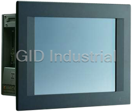
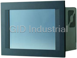
Advantech PPC-57/60 - Mini Panel PC with 5.7 " and 6.0" QVGA STN/Mono LCD Display
Part Number
PPC-57
Price
Request Quote
Manufacturer
ADVANTECH
Lead Time
Request Quote
Category
Panel PC
Specifications
BIOS
AMI 128 KB Flash memory
Construction
Plastic molding, optional metal PC/104 expansion cover
CPU with core logic
ALi M6117C, this is equivalent to a 80386SX CPU
Dimensions (W x H x D)
197.5 x 142.8 x 63.4 mm (7.8" x 5.6" x 2.5")
Disk Drive Housing
Supports one CompactFlash™ adapter
Ethernet (LAN)
Novell NE-2000 compatible, 10Base-T interface.
Expansion Slot
Supports up to two cascaded 16-bit PC/104 cards
FCC
Class B, CE approved
HDD
Supports up to two EIDE devices, auto-detect BIOS.
Input Voltage
18 ~ 30 VDCF
Interface
PS/2
Lifespan
More than 3 million touches
Lighttransmission
75%
Multi-mode parallel port
Configured to LPT1, LPT2, LPT3 or disabled. Supports SPP/EPP/ECP; D-SUB 25-pin connector.
Operating Temperature
0 ~ 45° C (32 ~ 113° F)
Output Rating
25 W
Output Voltage
+5 V @ 4 A, +12 V @ 0.5 A
PS/2 keyboard/mouse connector
Mini-DIN keyboard connector
RAM
One 72-pin SIMM socket, accepts 1, 4, 16 MB FPM or EDO DRAM
Relative Humidity
0 ~ 95% RH (non-condensing),
Resolution
1024 x 1024
Safety
Meets UL/CSA
Serial Ports
RS-232 x 1, RS-232/422/485 x 1 (DIP switch settings)
Software driver
Supports DOS
Type
4-wire resistive
VGA
C&T65545 chipset on board with 512 KB DRAM, supportspanel resolution up to 640 x 480 @ 256 colors.
Vibration
10 ~ 18 Hz, 1.5 mm peak-to-peak displacement 8 ~ 500 Hz, 1 G acceleration
Watchdog Timer
Adjustable period up to 62 seconds
Water resistance
Front panel meets NEMA 4 or IP 65
Weight
1.5 kg (3.3 lbs)
Datasheet

Extracted Text
PPC-57
386-based panel PC
with 5.7" LCD flat panel display
Copyright notice
This document is copyrighted January, 1999 by Advantech Co.,
Ltd. All rights are reserved. Advantech Co., Ltd. reserves the right
to make improvements to the products described in this manual at
any time without notice.
No part of this manual may be reproduced, copied, translated or
transmitted in any form or by any means without the prior written
permission of Advantech Co., Ltd. Information provided in this
manual is intended to be accurate and reliable. However,
Advantech Co., Ltd assumes no responsibility for its use, nor for
any infringements upon the rights of third parties which may result
from its use.
Acknowledgments
PPC-57S, PPC-57M, OPT112-57S, OPT112-57M and PPC-57
series are trademarks of Advantech Co., Ltd. IBM, PC/AT, and
PS/2 are trademarks of International Business Machines
Corporation. MS-DOS is a trademark of Microsoft Corporation.
All other brand and product names mentioned herein are trade-
marks or registered trademarks of their respective holders.
Part No. 2008005700
1st Edition Printed in Taiwan January 1999
ii
FCC Class B notes
This equipment has been tested and found to comply with the
limits for a Class B digital device, pursuant to Part 15 of the FCC
Rules. These limits are designed to provide reasonable protection
against harmful interference in a residential installation. This
equipment generates, uses, and can radiate radio frequency energy
and, if not installed and used in accordance with the instructions,
may cause harmful interference to radio communications. Howev-
er, there is no guarantee that interference will not occur in a
particular installation. If this equipment does cause harmful
interference to radio or television reception, which can be deter-
mined by turning the equipment off and on, the user is encouraged
to try to correct the interference by one or more of the following
measures:
- Reorient or relocate the receiving antenna
- Increase the separation between the equipment and receiver
- Connect the equipment into an outlet on a circuit different from
that to which the receiver is connected
- Consult the dealer or an experienced radio/TV technician for
help
iii
Packing List
Before you begin system installation, please make sure that the
following materials have been shipped:
• One PPC-57 with PCM-3866 all-in-one single board
• Accessories:
- One utility disk with BIOS and Ethernet utility programs
- One utility disk with SVGA utility programs and drivers
- One Y-type keyboard/mouse cable
- One plug-in power terminal
- One screw bag
- One waterproof sponge
- Four mounting clamps
- One ground wire
If any of these items is missing or damaged, contact your
distributor or sales representative immediately.
iv
Safety Instructions
1. Read these safety instructions carefully.
2. Keep this installation reference guide for later reference.
3. Disconnect this equipment from any AC outlet before cleaning. Do not use
liquid or spray detergents for cleaning. Use a damp cloth.
4. For pluggable equipment, the power outlet must be installed near the
equipment and must be easily accessible.
5. Keep this equipment away from humidity.
6. Put this equipment on a reliable surface during installation. Dropping it or
letting it fall could cause damage.
7. The openings on the enclosure are for air convection. Protect the
equipment from overheating. DO NOT COVER THE OPENINGS.
8. Make sure the voltage of the power source is correct before connecting the
equipment to the power outlet.
9. Position the power cord so that people cannot step on it. Do not place
anything over the power cord.
10. All cautions and warnings on the equipment should be noted.
11. If the equipment is not used for a long time, disconnect it from the power
source to avoid damage by transient over-voltage.
12. Never pour any liquid into an opening. This could cause fire or electrical
shock.
13. Never open the equipment. For safety reasons, the equipment should be
opened only by qualified service personnel.
14. If any of the following situations arises, get the equipment checked by
service personnel:
a. The power cord or plug is damaged.
b. Liquid has penetrated into the equipment.
c. The equipment has been exposed to moisture.
d. The equipment does not work well, or you cannot get it to work
according to the installation reference guide.
e. The equipment has been dropped and damaged.
f. The equipment has obvious signs of breakage.
15. DO NOT LEAVE THIS EQUIPMENT IN AN UNCONTROLLED
ENVIRONMENT WHERE THE STORAGE TEMPERATURE IS BELOW
-20° C (-4° F) OR ABOVE 60° C (140° F). IT MAY DAMAGE THE
EQUIPMENT.
The sound pressure level at the operator's position according to IEC 704-1:1982 is
equal to or less than 70 dB(A).
DISCLAIMER: This set of instructions is given according to IEC 704-1.
Advantech disclaims all responsibility for the accuracy of any statements
contained herein.
v
Wichtige Sicherheishinweise
1. Bitte lesen sie Sich diese Hinweise sorgfältig durch.
2. Heben Sie diese Anleitung für den späteren Gebrauch auf.
3. Vor jedem Reinigen ist das Gerät vom Stromnetz zu trennen. Verwenden Sie
Keine Flüssig-oder Aerosolreiniger. Am besten dient ein angefeuchtetes Tuch zur
Reinigung.
4. Die NetzanschluBsteckdose soll nahe dem Gerät angebracht und leicht zugänglich
sein.
5. Das Gerät ist vor Feuchtigkeit zu schützen.
6. Bei der Aufstellung des Gerätes ist auf sicheren Stand zu achten. Ein Kippen oder
Fallen könnte Verletzungen hervorrufen.
7. Die Belüftungsöffnungen dienen zur Luftzirkulation die das Gerät vor überhit-
zung schützt. Sorgen Sie dafür, daB diese Öffnungen nicht abgedeckt werden.
8. Beachten Sie beim AnschluB an das Stromnetz die AnschluBwerte.
9. Verlegen Sie die NetzanschluBleitung so, daB niemand darüber fallen kann. Es
sollte auch nichts auf der Leitung abgestellt werden.
10. Alle Hinweise und Warnungen die sich am Geräten befinden sind zu beachten.
11. Wird das Gerät über einen längeren Zeitraum nicht benutzt, sollten Sie es vom
Stromnetz trennen. Somit wird im Falle einer Überspannung eine Beschädigung
vermieden.
12. Durch die Lüftungsöffnungen dürfen niemals Gegenstände oder Flüssigkeiten in
das Gerät gelangen. Dies könnte einen Brand bzw. elektrischen Schlag auslösen.
13. Öffnen Sie niemals das Gerät. Das Gerät darf aus Gründen der elektrischen
Sicherheit nur von authorisiertem Servicepersonal geöffnet werden.
14. Wenn folgende Situationen auftreten ist das Gerät vom Stromnetz zu trennen und
von einer qualifizierten Servicestelle zu überprüfen:
a - Netzkabel oder Netzstecker sind beschädigt.
b - Flüssigkeit ist in das Gerät eingedrungen.
c - Das Gerät war Feuchtigkeit ausgesetzt.
d - Wenn das Gerät nicht der Bedienungsanleitung entsprechend funktioniert oder
Sie mit Hilfe dieser Anleitung keine Verbesserung erzielen.
e - Das Gerät ist gefallen und/oder das Gehäuse ist beschädigt.
f - Wenn das Gerät deutliche Anzeichen eines Defektes aufweist.
Der arbeitsplatzbezogene Schalldruckpegel nach DIN 45 635 Teil 1000 beträgt
70dB(A) oder weiger.
DISCLAIMER: This set of instructions is provided according to IEC704-1.
Advantech disclaims all responsibility for the accuracy of any statements
contained therein.
vi
Contents
Chapter 1 General Information................................. 1
1.1 Introduction .................................................................. 2
1.2 Specifications ................................................................ 3
General ........................................................................... 3
Standard SBC functions (PCM-3866) ........................... 3
Ethernet interface ........................................................... 3
SVGA/Flat panel interface (PCM-3866) ....................... 4
Power supply .................................................................. 4
Environmental specifications......................................... 4
Touchscreen (optional) .................................................. 4
1.3 LCD Specifications....................................................... 5
1.4 I/O Arrangement.......................................................... 6
1.5 Total Solution ............................................................... 7
1.6 Dimensions .................................................................... 8
1.7 Mounting ...................................................................... 9
Chapter 2 System Setup ......................................... 11
2.1 General ........................................................................ 12
2.2 Initial Setup ................................................................ 13
Installing software to the Compact Flash memory ...... 13
Installing a PS/2 mouse driver ..................................... 14
Installing a serial/COM port mouse driver into the
system ...................................................................... 14
2.3 Removing the Front or Rear Panel .......................... 15
2.4 Installing Memory (DRAM)...................................... 17
2.5 Installing a Compact Flash Adapter and 2.5" HDD 18
Installing a Compact Flash adapter.............................. 18
Installing a 2.5" HDD .................................................. 19
2.6 Installing the Power Terminal and Power Adapter 20
2.7 Installing a PC/104 Module ....................................... 21
2.8 Installing a Touchscreen............................................ 23
2.9 Exploded Diagram ..................................................... 25
vii
Chapter 3 Maintenance ........................................... 27
3.1 LCD Display ............................................................... 28
3.2 LCD Backlight ............................................................ 29
3.3 Power Supply .............................................................. 30
3.4 I/O Adapter................................................................. 31
3.5 PCM-3866 All-in-one Board ..................................... 32
Chapter 4 The Engine of the PPC-57 (PCM-3866). 33
4.1 Introduction ................................................................ 34
4.2 Jumpers and Connectors ........................................... 35
4.3 Locating Jumpers....................................................... 36
4.4 Locating Connectors .................................................. 37
4.5 Setting Jumpers.......................................................... 38
CMOS setup (J1).......................................................... 39
LCD display setup (J3) ................................................ 39
COM2 port setup.......................................................... 40
4.6 Connector Pin Assignments ...................................... 41
IDE hard drive connector (CN3).................................. 41
Touchscreen PS/2 connector (CN7)............................. 42
10Base-T Ethernet connector (CN5) ........................... 43
Main power connector (JP1) ........................................ 44
Flat panel display connector (CN4) ............................. 45
I/O connector (CN2) .................................................... 46
ISA extension connector (CN1) ................................... 47
4.7 I/O Connector Pin Assignments ............................... 49
COM1 RS-232 serial port (CN1) ................................. 49
Parallel port connector (CN3) ...................................... 50
Keyboard/mouse connector (CN5) .............................. 51
COM2 RS-232/422/485 serial port (CN2) ................... 51
4.8 PC/104 Connector Pin Assignments ......................... 52
PC/104 connector (JP2) ............................................... 52
4.9 Compact Flash Adapter Connector Pin Assignments
...................................................................................... 53
viii
Chapter 5 Software Configuration ......................... 55
5.1 Introduction ................................................................ 56
5.2 Utility Disk .................................................................. 56
5.3 How to Update BIOS ................................................. 57
5.4 Ethernet Utility........................................................... 58
Ethernet software configuration................................... 59
Chapter 6 AMI Flash BIOS Setup ........................... 61
6.1 System Test and Initialization .................................. 62
System configuration verification................................ 62
6.2 AMI BIOS setup ......................................................... 63
Entering setup .............................................................. 63
Standard CMOS setup.................................................. 64
Advanced CMOS setup................................................ 65
Peripheral setup............................................................ 66
Auto configuration with optimal settings .................... 67
Save settings and exit ................................................... 68
Exit without saving ...................................................... 68
Chapter 7 SVGA Setup............................................ 69
7.1 Sleep Mode .................................................................. 70
7.2 Software Support ....................................................... 71
7.3 Driver Installation...................................................... 72
Necessary prerequisites................................................ 72
Before you begin .......................................................... 72
Windows ...................................................................... 73
AutoCAD R12.............................................................. 75
Lotus 1-2-3 and Lotus Symphony................................ 77
VESA ........................................................................... 78
Word ............................................................................ 79
WordPerfect ................................................................. 80
ix
Appendix A Programming the Watchdog Timer... 83
A.1 Programming the Watchdog Timer ......................... 84
Appendix B Touchscreen (Optional) ..................... 87
B.1 Touchscreen Specifications ....................................... 88
Specifications ............................................................... 88
Operating system requirements ................................... 88
Appropriate applications .............................................. 88
B.2 Installation .................................................................. 89
Executing INSTALL.COM .......................................... 89
Installing the touchscreen driver .................................. 89
Calibrating the touchscreen ......................................... 89
B.3 Running the Setup Program ..................................... 90
Operation key ............................................................... 90
B.4 Removing the Touchscreen Driver ........................... 92
B.5 Touchscreen Driver Application Interface (API) ... 93
x
1
General Information
This chapter gives background
information on the PPC-57.
Sections include:
• Introduction
• Specifications
• LCD Specifications
• I/O Arrangement
• Total Solution
• Dimensions
• Mounting
CHAPTER
1.1 Introduction
The PPC-57 panel PC meets all of the requirements necessary to
serve as an industrial operator interface. This panel PC provides an
all-in-one 386 PC board with 5.7" STN color or mono LCD display,
on-board VGA, two COM ports (one RS-232, one RS-232/422/485),
one removable Compact Flash adapter, an external 16-bit PC/104
expansion slot, and optional touchscreen. The heart of the PPC-57
is a general purpose, miniature computer that is suitable for a
variety of applications.
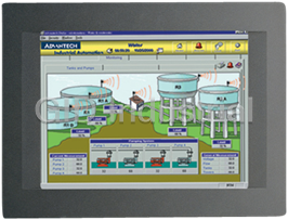
The PPC-57 is suitable for industry applications, including factory
automation equipment, automated production lines, precision
machinery, production process control, environmental control
equipment, terminal information systems and entertainment
management systems. Our panel PC is a reliable, cost-effective
solution to your application's processing requirements.
2 PPC-57 User's Manual
1.2 Specifications
General
• Construction: Plastic molding with an optional PC/104 metal cover
• Dimensions (W x H x D): 197.5 x 142.8 x 63.4 mm (7.76" x 5.61" x 2.49")
• Weight: 1.5 kg (3.3 lbs)
Standard SBC functions (PCM-3866)
• CPU with core logic: ALi M6117C, 40 MHz 80386SX CPU
• BIOS: AMI 128 KB Flash memory
• RAM: One 72-pin SIMM socket, accepts 1, 4, 16 FPM or EDO DRAM
(single side)
• IDE hard disk drive interface: Supports up to two Enhanced IDE
devices, auto-detect BIOS
• Multi-mode parallel port: Configured to LPT1, LPT2, LPT3 or disabled.
Supports SPP/EPP/ECP; D-SUB 25-pin connector (on I/O module)
• Serial ports: One serial RS-232 port, one serial RS-232/422/485 port (a
DIP switch setting) on I/O module. Two 16C550 compatible UARTs
• PS/2 keyboard/mouse connector: Mini-DIN keyboard connector (on I/O
module)
• Watchdog timer: Generates a system reset after an adjustable period
up to 62 seconds. Can be software enabled/disabled. Default factory
setting is disabled
• External expansion Slot: 104-pin connector, supports up to two
cascaded 16-bit PC/104 cards with +5 V and +12 V only
• Battery: 3 V @ 195 mA Lithium battery for CMOS backup
Ethernet interface
• Chipset: Realtek RTL8019AS
• Network (LAN): Novell NE2000 compatible, on-board 10Base-T
interface. Supports both boot ROM function and software drivers
Chapter 1 General Information 3
SVGA/Flat panel interface (PCM-3866)
• Chipset: C&T 65545
• Display memory: 512 KB DRAM
• Hardware Windows acceleration: 32-bit graphics engine. Hardware line
drawing and 64 x 64 x 2 hardware cursor
• Resolution: Panel resolution up to 640 x 480 @ 256 colors
Note: The resolution and hardware Windows acceleration of the
SVGA/flat panel interface is partially dependent on the
resolution of the flat panel.
Power supply
• Output rating: 25 W
• Input voltage: 18 ~ 30 V
DC
• Output voltage: +5 V @ 4 A, +12 V @ 0.5 A
Environmental specifications
• Operating temperature: 0 ~ 45°C (32° ~ 113° F)
• Relative humidity: 0 ~ 95% RH (non-condensing), 40° C
• Safety: Meets UL/CSA
• FCC Class B, CE approved
• Vibration: 10 ~ 18 Hz, 1.5 mm peak-to-peak displacement
18 ~ 500 Hz, 1 G acceleration
• Water resistance: Meets NEMA 4 or IP65 (front panel)
Touchscreen (optional)
• Type: Resistive
• Resolution: 1024 x 1024
• Light transmission: 68%
• Software driver: Supports DOS
• Lifetime: More than 3 million touches
4 PPC-57 User's Manual
1.3 LCD Specifications
Model PPC-57S PPC-57M
Display type STN color LCD Mono LCD
Max. colors or
256 colors 8 grayscale levels
grayscales
Size 5.7" 5.7"
KCS3224ASTT-X6 KS3224ASTT-FW-X1
LCD model
or compatible or compatible
Resolution 320 x 240 (1/4 VGA) 320 x 240 (1/4 VGA)
Brightness 110 cd/m² 200 cd/m²
Dot size (W x H) 0.34 x 0.34 0.34 x 0.34
Viewing angle
50° 30°
Temperature
0 ~ 50° C 0 ~ 50° C
LCD MTBF
62,000 hours 62,000 hours
Backlight MTBF
10,000 hours 10,000 hours
Chapter 1 General Information 5
1.4 I/O Arrangement
The I/O arrangement of the PPC-57 is shown below:
b c d
a
e
j i h g f
a. IDE connector f. Ethernet port
b. PC/104 slot
g. Parallel port
c. PS/2 keyboard and h. 24 V input connector
DC
mouse connector & chassis GND
d. Serial COM2 port i. LCD contrast
e. Serial COM1 port j. Slide power switch
Note: Serial port COM2 can be configured to operate in
RS-232, RS-422 or RS-485 mode. This is set by a
DIP switch on the upper side of the back cover.
Before attaching connectors, make sure the DIP
switch settings are suitable. (See page 40 for
COM2 port settings.)
6 PPC-57 User's Manual
1.5 Total Solution
Chapter 1 General Information 7
1.6 Dimensions
The PPC-57 can be placed on a shelf or a table, or mounted into a
panel. Cutout panel dimensions are as follows:
8 PPC-57 User's Manual
1.7 Mounting
If you decide to panel mount your PPC-57, four brackets are
included. Each bracket has one screw that fits in the keyhole slot
on the panel PC.
Chapter 1 General Information 9
10 PPC-57 User's Manual
2
System Setup
This chapter explains how to set up the
PPC-57's hardware.
Sections include:
• General
• Initial Setup
• Removing the Front or Rear Panel
• Installing Memory (DRAM)
• Installing a Compact Flash Adapter and
2.5" HDD
• Installing the Power Terminal and
Power Adapter
• Installing a PC/104 Module
• Installing a Touchscreen
• Exploded Diagram
CHAPTER
2.1 General
The PPC-57 PC-based system can monitor and sample the data of
several traditional PLC controllers simultaneously. It is able to
take full advantage of a wide range of available software pro-
grams, and upgrading can be achieved quickly and easily with the
use of various optional modules.
Customizing the PPC-57 is a simple matter. The DRAM, power
supply and I/O adapter are all readily accessible by removing the
front or rear panel.
Warning! Verify that all power sources have been discon-
nected from the PPC-57 before you install or
service it or any of its components or accesso-
ries. No power must be flowing within the PPC-57
at the start of any installation or servicing.
12 PPC-57 User's Manual
2.2 Initial Setup
Initial setup requires installation of the DRAM, Compact Flash
memory (or 2.5" HDD), power terminal, and 24 V power
DC
adapter. A touchscreen or a PC/104 module can be added as
options. This and the following sections describe how to complete
the initial assembly, as well as how to install the touchscreen and
PC/104 module upgrades.
Installing software to the Compact Flash memory
Software can be loaded in the PPC-57 using three methods:
Method 1: Use the COM or parallel port
Using transmission software, connect another PC to the PPC-57
with an appropriate cable and transmit the software to the PPC-57.
Method 2: Use a connection adapter board: PCD-1230 (option-
al)
The connection adapter board has three connectors. One is a
40-pin connector to connect to a personal computer's IDE port.
The other two are 44-pin connectors to connect with a Compact
Flash adapter or a 2.5" HDD. Load software from a drive. When
transferring software from an HDD or a Compact Flash memory,
pay attention to which drive is master and which drive is slave.
Method 3: Use the Ethernet
You can use the Ethernet port to download software to the
Compact Flash memory or HDD.
2.5" HDD
IDE port
Compact
Flash
adapter
Chapter 2 System Setup 13
Installing a PS/2 mouse driver
This section is for customers who buy a PPC-57 without the
touchscreen option. If you have purchased a PPC-57 with a
touchscreen, the PS/2 mouse driver is installed when you set up
the touchscreen driver (see Appendix B).
There is an execution file named INSTALL.COM in the root
directory of the system utility software disk. Run INSTALL.COM
to install the system software to your hard disk drive.
Installing the system software automatically creates a directory
named AMS in the root directory of your hard disk drive. Go to
the root directory of AMS, and then type M [Enter] or AMOUSE
to finish the installation.
You can type T [Enter] to test your mouse and PS/2 mouse driver
(for the PPC-57).
Warning! The LCD display is ¼ VGA, so the system utility
software driver is used for ¼ VGA. This is differ-
ent from the general mouse driver.
The touchscreen and PS/2 mouse can be operated simultaneously.
If you install the touchscreen driver, you must also install the PS/2
mouse driver at the same time (see Appendix B for installation
instructions). You do not need to install the PS/2 mouse driver
again.
Installing a serial/COM port mouse driver into the
system
You can use a general mouse driver to install a serial or COM port
mouse driver.
Warning! Before installing the serial port mouse driver, you
must remove the touchscreen driver or PS/2
mouse driver from system memory. Change the
root directory to ATS, and then type M [Enter] or
ATSMOUSE to finish the removal.
14 PPC-57 User's Manual
Note: The touchscreen driver or PS/2 mouse driver
cannot be simultaneously installed with a
serial/COM port mouse driver.
2.3 Removing the Front or Rear Panel
You only need to remove the front panel of your PPC-57 to
replace your LCD or backlight. To remove the front panel, first
verify that all power sources to the PPC-57 have been disconnect-
ed. Next, remove the two screws below the front panel. Then,
pinching an upper corner of the front panel closed with one of
your hands, pull the lower edge of the front panel firmly outward.
Chapter 2 System Setup 15
You need only remove the rear panel to replace the DRAM, power
supply, I/O adapter, and certain other components. To remove the
rear panel, first verify that all power sources to the PPC-57 have
been disconnected. Then remove the six screws on the rear panel
and pull it away from the PPC-57.
16 PPC-57 User's Manual
2.4 Installing Memory (DRAM)
The PPC-57 provides one 72-pin SIMM (single in-line memory
module) socket for installation of a single DRAM module (with
1 MB, 4 MB, or 16 MB DRAM). To install DRAM modules,
follow these steps:
1. Verify that all power sources to the PPC-57 have been discon-
nected.
2. Before installing DRAM, the rear panel must be opened. (See
Section 2.3.)
3. Slip the memory module into the socket at a 45 degree angle.
Note: The module can only fit into the SIMM socket one
way. Its chips must face the CHIPSET on the
PCM-3866 (all-in-one board), and its golden pins
must point down into the SIMM socket.
4. Push the module toward the vertical posts at both ends of the
socket until the module is upright and the retaining clips at
both ends of the socket click into place. When positioned
correctly, the pins on top of the vertical posts should corre-
spond to the circular holes on the ends of the module.
Chapter 2 System Setup 17
2.5 Installing a Compact Flash Adapter
and 2.5" HDD
Installing a Compact Flash adapter
1. Verify that all power sources to the PPC-57 have been discon-
nected.
2. Plug the Compact Flash adapter into the IDE-compatible slot
as shown in the picture below.
3. A Compact Flash memory card can be easily inserted or
removed from the adapter.
18 PPC-57 User's Manual
Installing a 2.5" HDD
1. Verify that all power sources to the PPC-57 have been discon-
nected.
2. Connect a cable from the HDD to the IDE-compatible slot on
the PPC-57 (CN3). Make sure that pin 1 on the cable corre-
sponds to pin 1 on the HDD.
Warning! When connecting the cable to the HDD, make
sure that pin 1 on the cable corresponds to pin 1
on the HDD. Improper connection will damage the
HDD.
Chapter 2 System Setup 19
2.6 Installing the Power Terminal and
Power Adapter
The power terminal supplied with the PPC-57 is plugged into its
24 V connector socket located beneath the PPC-57.
DC
To connect the power adapter:
1. Verify that all power sources to the PPC-57 have been discon-
nected.
2. Unscrew the screws on the power terminal. Insert the AC
power adapter wires into their proper connector holes (+, -,
GND) on the power terminal. Fasten the screws.
20 PPC-57 User's Manual
2.7 Installing a PC/104 Module
The PPC-57's PC/104 connector give you the flexibility to attach
PC/104 expansion modules. These modules perform the same
functions as traditional plug-in expansion cards. Using these
modules save space and valuable slots.
To install a PC/104 module:
1. Verify that all power sources to the PPC-57 have been discon-
nected.
2. Detach the steel cover behind the rear panel.
3. Plug the PC/104 module's male connectors into the ISA
expansion slot's female connectors by pressing the module
firmly but carefully.
4. Secure the two PC/104 modules onto the PPC-57.
5. Affix the PC/104 cover.
Chapter 2 System Setup 21
88.9 82.6
95.9
90.8 90.8
5.1
5.1
0
5.1 85.1
90.2
0
PC/104 module dimensions (mm ±5 %)
22 PPC-57 User's Manual
2.8 Installing a Touchscreen
A touchscreen should be installed only by a qualified technician.
The steps to install a touchscreen are as follows:
1. Verify that all power sources to the PPC-57 have been discon-
nected, and disconnect the touchscreen cable.
2. Remove the front panel. (See Section 2.3.)
3. Detach the plastic face from the front panel.
4. Remove the glass or defective touchscreen from the front
panel.
5. Attach the replacement touchscreen to the front panel with
industrial glue.
Important note: The touchscreen cable must be at the
reverse side of the front panel so that it can
properly attach to the connector on the
PCM-3866 board within the PPC-57.
6. Reattach the plastic face to the front panel.
7. Connect the touchscreen cable to the touchscreen control board
within the PPC-57, being careful to match the pin assignments.
8. Reattach the front panel to the PPC-57, all the while protecting
the touchscreen cable from sharp bending or cracking.
Chapter 2 System Setup 23
Installing a touchscreen
24 PPC-57 User's Manual
2.9 Exploded Diagram
The following exploded diagram is provided to help with assem-
bly or disassembly of the PPC-57.
Chapter 2 System Setup 25
26 PPC-57 User's Manual
3
Maintenance
Sections include:
• LCD Display
• LCD Backlight
• Power Supply
• I/O Adapter
• PCM-3866 All-in-one Board
CHAPTER
3.1 LCD Display
The LCD display should only rarely need replacing in the normal
working life of a PPC-57.
To replace the LCD display:
1. Verify that all power sources to the PPC-57 have been discon-
nected.
2. Open the front panel. (See Section 2.3.)
3. Remove the LCD from the steel chassis by first removing the
four screws.
4. Disconnect the cable from the LCD (marked "A" in the
diagram below) and the LCD inverter (marked "B").
28 PPC-57 User's Manual
3.2 LCD Backlight
To replace the backlight:
1. Verify that all power sources to the PPC-57 have been discon-
nected.
2. Open the front panel. (See Section 2.3.)
3. Remove the LCD from the steel chassis.
4. Disconnect the cables from the LCD and the LCD inverter.
5. Remove the screw which attaches the LCD backlight to the
LCD display. Pull the backlight out horizontally.
6. To insert the backlight and reassemble the unit, follow the
reverse of the above procedures.
Warning: The backlight is fragile. Use caution when hand-
ing or replacing it.
Chapter 3 Maintenance 29
3.3 Power Supply
To repair or replace the power supply:
1. Verify that all power sources to the PPC-57 have been discon-
nected.
2. Open the rear cover. (See Section 2.3.)
3. Remove the four screws attaching the power supply to the CPU
board.
4. Disconnect the cable from the power supply.
5. Replace the power supply and reassemble.
Warning: Shut off all power to the PPC-57 before attempt-
ing to repair the power supply. Switch off the
power and unplug the unit.
30 PPC-57 User's Manual
3.4 I/O Adapter
To replace or service the I/O adapter, follow these steps:
1. Verify that all power sources to the PPC-57 have been discon-
nected.
2. Remove the rear cover. (See Section 2.3.)
3. Remove the screw which attaches the I/O adapter to the CPU
board (PCM-3866).
4. Replace the I/O adapter and reassemble the PPC-57.
Chapter 3 Maintenance 31
3.5 PCM-3866 All-in-one Board
To replace or service the PCM-3866:
1. Verify that all power sources to the PPC-57 have been discon-
nected.
2. Remove the rear cover. (See Section 2.3.)
3. Remove the power supply, touchscreen control board, I/O
adapter, and other attachments. (See Sections 3.3 and 3.4.)
4. Replace the PCM-3866, reattach the components previously
removed, and reassemble the PPC-57.
32 PPC-57 User's Manual
4
The Engine of the
PPC-57 (PCM-3866)
This chapter tells how to set up the engine
of the PPC-57. It contains instructions on
jumpers, and on connecting peripherals,
switches, and indicators.
Sections include:
• Introduction
• Jumpers and Connectors
• Locating Jumpers
• Locating Connectors
• Setting Jumpers
• Connector Pin Assignments
• I/O Connector Pin Assignments
• PC/104 Connector Pin Assignment
• Compact Flash Adapter Connector Pin
Assignments
CHAPTER
4.1 Introduction
The PCM-3866 in the PPC-57 is specially designed to be an
ultra-compact all-in-one SBC which incorporates a PC/104
connector into its design, accommodating easy expansion to meet
your application needs.
The board uses a newly-developed 386SX embedded microcon-
troller (ALi's M6117C). This highly integrated, low-voltage single
chip combines Intel's 386SX compatible microprocessor and ALi's
M1217 chipset. All the features required of a PC-compatible
embedded controller are included in the CPU board.
The PCM-3866 is equipped with a 32-bit SVGA/LCD interface, a
72-pin DRAM SIMM socket, one Enhanced IDE connector, a
multi-mode parallel port, a keyboard connector and two standard
serial ports.
Offering superior configuration flexibility, the PCM-3866 is a
compact 145 mm (L) x 102 mm (W) (5.9" x 4.2"). Its built-in
CPU, highly compact size and numerous features make it an ideal
cost/performance solution for all kinds of embedded applications.
34 PPC-57 User's Manual
4.2 Jumpers and Connectors
Connectors on the board link it to external devices such as hard
disk drives or a keyboard. In addition, the board has a number of
jumpers that allow you to configure your system to suit your
application.
The table below lists the function of each of the board jumpers and
connectors:
Jumpers
Label Function
J1 CMOS setup
J2 Reset
J3 LCD select
DIP switch
Label Function
SW1 COM2 RS-232/422/485 select
Connectors
Label Function
CN1 ISA extension connector
CN2 I/O connector
CN3 IDE hard disk connector
CN4 ¼ VGA flat panel display connector
CN5 10Base-T Ethernet connector
CN6 Watchdog programming connector
CN7 Touchscreen connector
CN10 6.0" full VGA flat panel display connector
JP1 Main power connector
Chapter 4 The Engine of the PPC-57 (PCM-3866) 35
4.3 Locating Jumpers
COM2 RS-232/422/485
select (SW)
LCD display
setup (J3)
CMOS setup (J1)
36 PPC-57 User's Manual
4.4 Locating Connectors
I/O connector Flat panel display
(CN2) connector (CN4)
10Base-T
Ethernet
connector
(CN5)
Touchscreen
connector
(CN7)
SIMM
Main power
connector (JP1)
ISA extension IDE hard disk
connector (CN1) connector (CN3)
Chapter 4 The Engine of the PPC-57 (PCM-3866) 37
4.5 Setting Jumpers
You may configure your card to match the needs of your applica-
tion by setting jumpers. A jumper is the simplest kind of electrical
switch. It consists of two metal pins and a small metal clip (often
protected by a plastic cover) that slides over the pins to connect
them. To "close" a jumper, connect the pins with the clip. To
"open” a jumper, remove the clip. Sometimes a jumper will have
three pins, labeled 1, 2, and 3. In this case, connect either pins 1
and 2 or 2 and 3.
3
2
1
Open Closed Closed 2-3
The jumper settings are schematically depicted in this manual as
follows:
1
Open Closed Closed 2-3
A pair of needle-nose pliers may be helpful when working with
jumpers.
If you have any doubts about the best hardware configuration for
your application, contact your local distributor or sales representa-
tive before you make any changes.
Generally, a standard cable is all that is needed to make most
connections.
38 PPC-57 User's Manual
Warning! Always completely disconnect the power cord
from your board whenever you are working on it.
Do not make connections while the power is on,
because sensitive electronic components can be
damaged by a sudden rush of power.
Caution! Always ground yourself to remove any static
charge before touching the board. Modern
electronic devices are very sensitive to static
electric charges. Use a grounding wrist strap at
all times. Place all electronic components on a
static-dissipative surface or in a static-shielded
bag when they are not in the chassis.
CMOS setup (J1)
CMOS setup
*3.6 V Battery on Clear CMOS
J1 1-2 2-3
* default setting
LCD display setup (J3)
LCD display setup
5 V LCD module 3 V LCD module
J3 1-2 2-3
Chapter 4 The Engine of the PPC-57 (PCM-3866) 39
COM2 port setup
PCM-3866 DIP switch settings
SW RS-232* RS-422 RS-485
1 ON OFF OFF
2 ON OFF OFF
3 ON OFF OFF
4 ON OFF OFF
5 OFF ON ON
6 OFF ON ON
7 OFF ON ON
8 OFF ON ON
9 ON OFF OFF
10 OFF ON OFF
11 OFF OFF ON
12 N/V N/V N/V
* default setting
Note: Refer to page 51 for pin assignments.
40 PPC-57 User's Manual
4.6 Connector Pin Assignments
IDE hard drive connector (CN3)
PCM-3866 IDE hard drive connector
Pin Signal Pin Signal
1 IDE RESET* 2 GND
3 DATA 7 4 DATA 8
5 DATA 6 6 DATA 9
7 DATA 5 8 DATA 10
9 DATA 4 10 DATA 11
11 DATA 3 12 DATA 12
13 DATA 2 14 DATA 13
15 DATA 1 16 DATA 14
17 DATA 0 18 DATA 15
19 SIGNAL GND 20 N/C
21 N/C 22 GND
23 IO WRITE* 24 GND
25 IO READ* 26 GND
27 IO CHANNEL READY 28 BALE
29 N/C 30 GND
31 IRQ14 32 IOCS16*
33 ADDR 1 34 N/C
35 ADDR 0 36 ADDR 2
37 HARD DISK SELECT 0* 38 HARD DISK SELECT 1*
39 N/C 40 GND
41 VCC 42 VCC
43 GND 44 N/C
* active low
The built-in Enhanced IDE (integrated device electronics) control-
ler supports up to two IDE devices.
The system BIOS can automatically detect the IDE hard disk
intalled in your system.
Chapter 4 The Engine of the PPC-57 (PCM-3866) 41
Connecting drives is done in a daisy-chain fashion and requires a
1 x 44-pin to 2 x 44-pin flat-cable connector.
Wire number 1 on the cable is red or blue, and the other wires are
gray.
1. Connect one end of the cable to CN3. Make sure that the red
(or blue) wire corresponds to pin 1 on the connector, which is
labeled on the board (on the right side).
2. Plug the other end of the cable into the Enhanced IDE hard
drive, with pin 1 on the cable corresponding to pin 1 on the
hard drive. (See your hard drive's documentation for the
location of the connector.)
Connect a second drive as described above.
Unlike floppy drives, IDE hard drives can connect to either end of
the cable. If you install two drives, you will need to set one as the
master and one as the slave by using jumpers on the drives. If you
install just one drive, set it as the master.
Touchscreen PS/2 connector (CN7)
PCM-3866 touchscreen PS/2 connector
Pin Signal
1 MS CLOCK
2 MS DATA
3 PS2MSCLOCK
4 PS2MSDATA
5 GND
6 VCC
42 PPC-57 User's Manual
10Base-T Ethernet connector (CN5)
PCM-3866 10Base-T Ethernet connector
Pin Signal
1 TX+
2 TX-
3 RX+
4 N/C
5 N/C
6 RX-
7 N/C
8 N/C
The PCM-3866 is equipped with a high performance 16-bit
Ethernet interface which is fully compliant with IEEE 802.3 10
Mbps CSMA/CD standards. It is supported by all major network
operating systems and is 100% Novell NE2000 compatible.
Configuration of the Ethernet is very easy and can be done via the
RSET8019.EXE program included on the utility disk. This
program enables you to view the current Ethernet configuration, to
reconfigure the Ethernet interface (IRQ, I/O address, etc.), and to
execute useful diagnostic functions. (See Chapter 5 for detailed
information.)
The RSET8019.EXE program provides two ways to configure the
Ethernet interface. Configuration can be done automatically when
you choose the PnP (Plug and Play) option. Alternatively, when
you choose the jumperless option, the following IRQ and I/O
address settings are available (see over).
Chapter 4 The Engine of the PPC-57 (PCM-3866) 43
PCM-3866 Ethernet settings
IRQ option I/O address range
Jumperless 2,3,4,5,10, 11,12,15 200-300H
configuration
Default settings: IRQ=11, I/O Address=300H
Note: You can select an IRQ from the options shown
above, but make sure your selection does not
conflict with other I/O devices.
Main power connector (JP1)
PCM-3866 main power connector
Pin Signal
1 VCC
2 VCC
3 GND
4 ENAVEE
5 VEESAFE
6 GND
7 ENABKL
8 +12 V
Flat panel display connector (CN4)
PCM-3866 flat panel display connector
Pin Signal
1 FLM
2LP
3 SHFCLK
4 ENAVEE
5 VCC
6 GND
7 VEESAFE
8P0
9P1
10 P2
11 P3
12 P8
13 P9
14 P10
15 P11
CN4 consists of a 15-pin header. Power supplies (+12 V) present
on JP1 depend on the supply connected to the board.
The PCM-3866 provides a bias control signal on JP1 which can be
used to control the LCD bias voltage. It is recommended that the
LCD bias voltage not be applied to the panel until the logic supply
voltage (+5 V) and panel video signals are stable. Under normal
operation, the control signal (ENAVEE) is active high.
I/O connector (CN2)
PCM-3866 I/O connector
Pin Signal Pin Signal
1 STROBE* 31 VCC
2D0 32 D4
3D1 33 D5
4D2 34 D6
5D3 35 D7
6 BUSY 36 ACK*
7 SLCT 37 PE
8 INIT* 38 SLCTINI*
9 AUTOFD* 39 ERR*
10 GND 40 GND
11 KBDATA 41 PS2MSDATA
12 KBCLOCK 42 PS2MSCLOCK
13 GND 43 GND
14 NC 44 NC
15 NC 45 NC
16 NC 46 GND
17 GND 47 DCD1
18 RxD1 48 Tx1
19 DTR1 49 DSR
20 RTS1 50 CTS1
21 RI1 51 GND
22 GND 52 DCD2/TxD-
23 RxD2/TxD+ 53 TxD2/RxD+
24 DTR2/RxD- 54 DSR2
25 RTS2 55 CTS2
26 RI2 56 GND
27 GND 57 GND
28 GND 58 GND
29 GND 59 GND
30 GND 60 VCC
* active low
46 PPC-57 User's Manual
ISA extension connector (CN1)
PCM-3866 ISA extension connector (pins 1 through 60)
Pin Signal Pin Signal
1 IOCHK* 31 GND
2 GND 32 M16
3 RESETDRV 33 IQ16
4 VCC 34 IRQ10
5 IRQ9 35 IRQ11
6 DRQ2 36 IRQ12
7 0WS* 37 IRQ15
8 +12 V 38 IRQ14
9 GND 39 DACK0
10 SMEMW* 40 DRQ0
11 SMEMR* 41 DACK5
12 IOW* 42 DRQ5
13 IOR* 43 DECK6
14 DACK3* 44 DRQ6
15 DRQ3 45 DACK7
16 DACK1* 46 DRQ7
17 DRQ1 47 VCC
18 REFRESH* 48 MST
19 SYSCLK 49 GND
20 IRQ7 50 GND
21 IRQ6 51 SD7
22 IRQ5 52 SD6
23 IRQ4 53 SD5
24 IRQ3 54 SD4
25 DACK2* 55 SD3
26 TC 56 SD2
27 BALE 57 SD1
28 VCC 58 SD0
29 OSC 59 IORDY
30 GND 60 AEN
* active low
See overleaf for details of pins 61 through 100.
Chapter 4 The Engine of the PPC-57 (PCM-3866) 47
PCM-3866 ISA extension connector (pins 61 through 100)
Pin Signal Pin Signal
61 SA19 81 GND
62 SA18 82 SBHE
63 SA17 83 LA23
64 SA16 84 LA22
65 SA15 85 LA21
66 SA14 86 LA20
67 SA13 87 LA19
68 SA12 88 LA18
69 SA11 89 LA17
70 SA10 90 MRD
71 SA9 91 MWT
72 SA8 92 SD8
73 SA7 93 SD9
74 SA6 94 SD10
75 SA5 95 SD11
76 SA4 96 SD12
77 SA3 97 SD13
78 SA2 98 SD14
79 SA1 99 SD15
80 SA0 100 VCC
See previous page for details of pins 1 through 60.
48 PPC-57 User's Manual
4.7 I/O Connector Pin Assignments
COM1 RS-232 serial port (CN1)
PCM-3866-I/0 1 COM1 RS-232 serial port
Pin Signal
1 DCD
2 RxD
3 TxD
4 DTR
5 GND
6 DSR
7 RTS
8 CTS
9RI
Chapter 4 The Engine of the PPC-57 (PCM-3866) 49
Parallel port connector (CN3)
PCM-3866-I/O 1 parallel port connector
Pin Signal
1 STROBE*
2D0
3D1
4D2
5D3
6D4
7D5
8D6
9D7
10 ACK*
11 BUSY
12 PE
13 SLCT
14 AUTOFD*
15 ERR*
16 INIT*
17 SLCTINI*
18 GND
19 GND
20 GND
21 GND
22 GND
23 GND
24 GND
25 GND
* active low
50 PPC-57 User's Manual
COM2 RS-232/422/485 serial port (CN2)
PCM-3866-I/O 1 COM2 RS-232/422/485 serial port
RS-232 RS-422 RS-485
Pin Signal Signal Signal
1 DCD TxD- TxD- (Data-)
4 DTR RxD- RxD- (Data-)
2 RxD TxD+ TxD+ (Data+)
3 TxD RxD+ RxD+ (Data+)
5 GND GND GND
6 DSR DSR DSR
7 RTS RTS RTS
8 CTS CTS CTS
9RI RI RI
In a typical RS-485 application, the host device requests data from
a slave module that listens for the response. The host transmits and
receives data on the same pair of wires. Software handles the flow
control; no other wires are needed. Pin assignments appear in the
table. Pins 1 and 4 share the Data- wire. Pins 2 and 3 share the
Data+ wire.
Keyboard/mouse connector (CN5)
PCM-3866-I/O 1 keyboard/mouse connector
Pin Signal
1 KB DATA
2 PS2MSDATA
3 GND
4 VCC
5 KB CLOCK
6 PS2MSCLOCK
Chapter 4 The Engine of the PPC-57 (PCM-3866) 51
4.8 PC/104 Connector Pin Assignments
PC/104 connector (JP2)
PCM-3866-ISA 1 PC/104 connector
CN2 CN3
Pin Signal Signal Signal Signal
Row A Row B Row A Row B
1 IOCHK* GND GND GND
2 SD7 RESTDRV SBHE* MB16*
3 SD6 VCC LA23 IO16*
4 SD5 IRQ9 LA22 IRQ10
5 SD4 N/C LA21 IRQ11
6 SD3 DRQ2 LA20 IRQ12
7 SD2 N/C LA19 IRQ15
8 SD1 0WS* LA18 IRQ14
9 SD0 +12 V LA17* DACK0*
10 IORDY GND MRD* DRQ0*
11 AEN SMEMW* MWT* DACK5
12 SA19 SMEMR* SD8 DRQ5
13 SA18 IOW* SD9 DACK6*
14 SA17 IOR* SD10 DRQ6
15 SA16 DACK3* SD11 DACK7*
16 SA15 DRQ3 SD12 DRQ7
17 SA14 DACK1* SD13
18 SA13 DRQ1 SD14 MST*
19 SA12 RFSH* SD15 GND
20 SA11 ATCLKO (KEY) GND
21 SA10 IRQ7
22 SA9 IRQ6
23 SA8 IRQ5
24 SA7 IRQ4
25 SA6 IRQ3
26 SA5 DACK2*
27 SA4 TC
28 SA3 BALE
29 SA2 VCC
30 SA1 OSC
31 SA0 GND
32 GND GND
* active low
52 PPC-57 User's Manual
4.9 Compact Flash Adapter Connector Pin
Assignments
PCM-3866 IDE Compact Flash adapter connector
Pin Signal Pin Signal
1 GND 26 CD1*
2 SD3 27 SD11
3 SD4 28 SD12
4 SD5 29 SD13
5 SD6 30 SD14
6 SD7 31 SD15
7 H1CS0* 32 H1CS1*
8-- 33 --
9 HOE* 34 IOR
10 -- 35 IOW
11 -- 36 WE*
12 -- 37 IRQ14
13 VCC 38 VCC
14 -- 39 CSEL*
15 -- 40 --
16 -- 41 RST
17 -- 42 IORDY
18 SA2 43 DRQ
19 SA1 44 DACK
20 SA0 45 BVD1
21 SD0 46 --
22 SD1 47 SD8
23 SD2 48 SD9
24 IO16 49 SD10
25 CD2* 50 GND
* active low
Chapter 4 The Engine of the PPC-57 (PCM-3866) 53
54 PPC-57 User's Manual
5
Software Configuration
This chapter shows you how to configure
the card to match your application
requirements. AMI System BIOS is
covered in Chapter 6.
Sections include:
• Introduction
• Utility Disk
• How to Update BIOS
• Ethernet Utility
CHAPTER
5.1 Introduction
The PCM-3866 system BIOS and custom drivers are located in a
128 KB, 32-pin Flash ROM device, designated U5. A single Flash
chip holds the system BIOS and VGA BIOS. The display type can
be configured via software. This method minimizes the number of
chips and eases configuration. You can change the display BIOS
simply by reprogramming the Flash chip.
5.2 Utility Disk
The PCM-3866 is supplied with a software utility disk. This disk
contains the necessary files for setting up the VGA display.
Directories and files on the disk are as follows:
README.DOC
AMIFLASH.EXE
57SYS.ROM
57CSTN.ROM
57MONO.ROM
ETHERNET.EXE
ON.COM
OFF.COM
AMIFLASH.EXE
This program allows you to write the VGA BIOS files to the BIOS
Flash ROM. All the VGA files are already formatted for the
PCM-3866 with .ROM extensions. See README.DOC. They are
custom written and can be made available upon request.
57SYS.ROM
This binary file contains the system BIOS.
57CSTN.ROM
Supports 320 x 240 color STN DD 8-bit displays
(KYOCERA KCS3224ASTT-X6 5.7").
57MONO.ROM
Supports 320 x 240 monochrome displays
(KYOCERA KS3224ASTT-FW-X1 5.7").
56 PPC-57 User's Manual
ETHERNET.EXE
This is a compressed file containing ethernet drivers and the utility
for the Realtek 8019AS chip (see page 58).
5.3 How to Update BIOS
You can program your on-board BIOS as follows:
1. Apply power to the PCM-3866 with a color STN display
attached. This is the default setting for the PCM-3866. Make
sure that the AMIFLASH.EXE and *.ROM files are located in
the working drive.
Note: Make sure that you do not run AMIFLASH.EXE
while your system is operating in EMM386 mode.
2. At the prompt, type AMIFLASH.EXE and press Frequently asked questions How does Industrial Trading differ from its competitors? Is there a warranty for the PPC-57?
Which carrier will Industrial Trading use to ship my parts?
Can I buy parts from Industrial Trading if I am outside the USA?
Which payment methods does Industrial Trading accept?
Quality We are industry veterans who take pride in our work Protection Avoid the dangers of risky trading in the gray market Access Our network of suppliers is ready and at your disposal Savings Maintain legacy systems to prevent costly downtime Speed Time is of the essence, and we are respectful of yours OPERATOR INTERFACE 10.4 INCH LCD DISPLAY Advantech AWS-8124TP Operator Interace 12.1 inch TFT LCD, 4 PCI slot backplane, 3.5 inch FDD, 80 W A... Advantech AWS-8124TP-T Operator Interface AWS-8124TP with resistive touchscreen (RS-232 interface) Advantech AWS-8124T-T Operator Interface. 3-1.5AMP | 100-240VAC Advantech AWS-8124T-TC2, AWS-8124T-T bundle PCA-6770F CPU card Request a Quote The quote request has been received Close Facing challenges or have inquiries? Feel free to contact us! Call Us +1-469-283-2440 immediately. This will
allow you to enter Setup.
Chapter 6 AMI Flash BIOS Setup 63
Standard CMOS setup
When you choose the STANDARD CMOS SETUP option from
the INITIAL SETUP SCREEN menu, the screen shown below is
displayed. This standard Setup Menu allows users to configure
system components such as date, time, hard disk drive and floppy
drive. Once a field is highlighted, on-line help information is
displayed at the bottom left of the menu screen.
Standard CMOS setup screen
64 PPC-57 User's Manual
Advanced CMOS setup
By choosing the ADVANCED CMOS SETUP option from the
INITIAL SETUP SCREEN menu, the screen below is displayed.
This sample screen contains the manufacturer's default values for
the PCM-3866.
Advanced BIOS setup screen
Chapter 6 AMI Flash BIOS Setup 65
Peripheral setup
By choosing the INTEGRATED PERIPHERALS option from the
INITAL SETUP SCREEN menu, the screen below is displayed.
This sample screen contains the manufacturer's default values for
the PCM-3866.
66 PPC-57 User's Manual
Auto configuration with optimal settings
This option allows the user to load optimal settings. It loads the
default system values directly from ROM. If the stored record
created by the setup program becomes corrupted (and therefore
unusable), these defaults will load automatically when you turn on
the PPC-57.
You can load optimal default settings by choosing "Y" in the
screen above. The high-performance settings are the most favor-
able values for optimum system performance.
Chapter 6 AMI Flash BIOS Setup 67
Save settings and exit
If you select this option and press [Enter].
The symbol stands for target disk, which is that disk onto
which you wish to install the system sofware. Key in C: or D:.
Installing the system software automatically creates a directory
named ATS in the root directory of your hard disk drive.
Installing the touchscreen driver
1. Go to the root directory of ATS.
2. Type M [Enter] (or ATSMOUSE).
Calibrating the touchscreen
1. Run the Setup program (see Section B3).
2. Select the VGA modes which your program requires.
3. Run the calibration function for each VGA mode which has
been selected. You can test them after calibration, and then exit
to save the settings.
Appendix B Touchscreen 89
B.3 Running the Setup Program
1. Go to the root directory of ATS.
2. Key in S [Enter] (or ATSDOSCP).
Operation keys
1. Use the [↑] and [↓] keys to move the cursor up or down to the
desired function.
2. Use the [←] and [→] keys to select the desired variable setting.
3. Press [Enter] to confirm the setting.
Settings for running the touchscreen setup program are:
1. Device type: PS/2 port (factory default)
This setting allows the touchscreen's operating software to
locate the proper device type. The proper device for the
PPC-57 is the PS/2 port.
2. Button Mode
This is the way in which the touchscreen simulates the action
of a left mouse button. Four options are presented:
a) Stream mode: The touchsreen does not simulate the button
mode, but only outputs its coordinates. This mode is normally
not selected.
b) Lift-off mode: Activates the moment a finger or stylus lifts
off the touchscreen.
c) Touch down mode: Activates the moment a finger or stylus
presses against the touchscreen.
d) Drag drop mode: Activates whenever a finger or stylus
presses against the touchscreen. This is the factory default
setting.
3. Calibration settings
These are the corresponding location file numbers for different
VGA mode resolutions.
90 PPC-57 User's Manual
Calibration settings
Location file number VGA mode resolution
VGA #0D 320 x 200 (40 x 75)
VGA #0E 640 x 200 (80 x 25)
VGA #0F 640 x 350 (80 x 25)
VGA #10 640 x 350 (80 x 25)
VGA #11 640 x 480 (80 x 30)
VGA #12 640 x 480 (80 x 30)
VGA #13 320 x 200 (40 x 25)
We suggest that you select the location file number VGA #12.
Use the [ ←] and the [→] keys to select the desired variable, then
press [Enter] to set the four corners of the screen (top-left,
top-right, bottom-left, and bottom-right, following the directions
on the screen). Test the touchscreen by touching it.
Touch the crisscross
4. Save and Exit
This saves all selected variables to data files and leaves the
setup program.
Appendix B Touchscreen 91
B.4 Removing the Touchscreen Driver
1. Go to the root directory to ATS.
2. Type M [Enter] or ATSMOUSE to finish the removal.
File name: ATSMOUSE.API
Description:
A user's application program that can perform the same functions
as the driver via Int 33h. The driver will perform some functions
according to data in the AX register. The ATSMOUSE.API
application program can transfer the parameter to the driver by
BX, CX and DX registers, and some functions may be transferred
to the ES, DI and SI registers.
92 PPC-57 User's Manual
B.5 Touchscreen Driver Application
Interface (API)
The device driver supports some functions compatible with the
mouse driver, as listed below:
Compatible functions supported by the device driver
AX Description
0000h Install flag and reset
0001h Show cursor
0002h Hide cursor
0003h Get position and button status
0004h Set cursor position
0005h Get button press information
0006h Get button release information
0007h Set minimum and maximum horizontal position
0008h Set minimum and maximum vertical position
0009h Set graphics cursor block
000Ah Set text cursor
000Bh Read motion counters
000Ch Set user-defined subroutine input mask
0014h Swap user interrupt vector
Device drivers provide some functional support for application
software which sets the following touchscreen functions:
Touchscreen functions supported by device drivers
AX Description
8000h Get touchscreen device driver information
8002h Get touchscreen position and status
8003h Get touchscreen raw input
8005h Set touchscreen options
8006h Get touchscreen options table address
Appendix B Touchscreen 93
Function: Get touchscreen device driver information
Input: AX = 8000h
Output:
AX = "AT" identification code
BL = 4, Type: PS/2
BH = interrupt request number IRQ
CX = Interrupt vector number
DX = device driver version e.g. 0864h=8.64
Function: Get touchscreen position and status
Input: AX = 8002H
Output:
BL = button status: BIT-0 left button status, 0: release, 1:
press BIT-1 right button status, 0: release, 1: press
other bytes retained
BH = press status: BIT-3 press flag, 0: release, 1: press
other bytes retained
CX = Horizontal vector (X)
DX = Vertical vector (Y)
Function: Get touchscreen initial input
Input: AX = 8003H
Output:
CX = Horizontal vector (X)
DX = Vertical vector (Y)
BL = press status: BIT-3 press flag, 0: release, 1: press other
bytes retained
Function: Set touchscreen function
Input: AX =8005H
BX = Function type
DX =parameter 1
CX = parameter 2
DI = parameter 3
SI = parameter 4
94 PPC-57 User's Manual
Output:
AX = 0, execute OK
AX = 1, execute fail
Example:
When BX = 1, it is set for fictitious button mode
DL (fictitious button mode)
= 1: Stream mode
= 2: Lift off mode
= 3: Touch down mode
= 4: Drag drop mode
When BX = 2, set calibration address
DL (calibration address)
= 1: address table #1
= 2: address table #2
= 3: address table #3
...
=15: address table #15
When BX = 3, download addresses to address table which is
selected by the address table selector.
DX = Horizontal (X) minimum value
CX = Vertical (Y) minimum value
SI = Horizontal (X) maximum value
DI = Vertical (Y) maximum value
When BX = 4, start using select address table is present addresses
DL (start using select address table number)
= 1: address table #1
= 2: address table #2
= 3: address table #3
...
= 15: address table #15
Appendix B Touchscreen 95
Function: Get touchscreen parameter function table address
Input: AX = 8006H
Output:
AX = 0
ES: BX = address of parameter table (segment = offset)
Illustration:
When the system starts, the T/S driver will load ATSMOUSE.INI
into the parameter table area to support the obtaining of video
mode addresses for switching to any one video mode automatical-
ly.
Parameter format
Fictitious button mode : 1 byte
Address selection : 1 byte
Address table #1 : 4 word (video mode: 00h)
Address table #2 : 4 word (video mode: 01h)
Address table #3 : 4 word (video mode: 02h)
Address table #4 : 4 word (video mode: 03h)
Address table #5 : 4 word (video mode: 04h)
Address table #6 : 4 word (video mode: 05h)
Address table #7 : 4 word (video mode: 06h)
Address table #8 : 4 word (video mode: 07h)
Address table #9 : 4 word (video mode: 0Dh)
Address table #10 : 4 word (video mode: 0Eh)
Address table #11 : 4 word (video mode: 0Fh)
Address table #12 : 4 word (video mode: 10h)
Address table #13 : 4 word (video mode: 11h)
Address table #14 : 4 word (video mode: 12h)
Address table #15 : 4 word (video mode: 13h)
Reserved : 4 word
Parameter file name : 126 byte, includes path and end
character = CHR(0)
96 PPC-57 User's Manual
Address table format
Horizontal (X) minimum value: 1 word
Vertical (Y) minimum value: 1 word
Horizontal (X) maximum value: 1 word
Vertical (Y) maximum value: 1 word
Note: Do not change the contents of the parameter
directly, because this may cause the touchscreen
to malfunction. Set the parameters of each
touchscreen function, and the drivers will subse-
quently change the contents of the parameters
automatically. This is the best way to reach your
application.
Appendix B Touchscreen 97
98 PPC-57 User's Manual

Why buy from GID?


Related Products

![]()
![]()

![]()

What they say about us
FANTASTIC RESOURCE
One of our top priorities is maintaining our business with precision, and we are constantly looking for affiliates that can help us achieve our goal. With the aid of GID Industrial, our obsolete product management has never been more efficient. They have been a great resource to our company, and have quickly become a go-to supplier on our list!
Bucher Emhart Glass
EXCELLENT SERVICE
With our strict fundamentals and high expectations, we were surprised when we came across GID Industrial and their competitive pricing. When we approached them with our issue, they were incredibly confident in being able to provide us with a seamless solution at the best price for us. GID Industrial quickly understood our needs and provided us with excellent service, as well as fully tested product to ensure what we received would be the right fit for our company.
Fuji
HARD TO FIND A BETTER PROVIDER
Our company provides services to aid in the manufacture of technological products, such as semiconductors and flat panel displays, and often searching for distributors of obsolete product we require can waste time and money. Finding GID Industrial proved to be a great asset to our company, with cost effective solutions and superior knowledge on all of their materials, it’d be hard to find a better provider of obsolete or hard to find products.
Applied Materials
CONSISTENTLY DELIVERS QUALITY SOLUTIONS
Over the years, the equipment used in our company becomes discontinued, but they’re still of great use to us and our customers. Once these products are no longer available through the manufacturer, finding a reliable, quick supplier is a necessity, and luckily for us, GID Industrial has provided the most trustworthy, quality solutions to our obsolete component needs.
Nidec Vamco
TERRIFIC RESOURCE
This company has been a terrific help to us (I work for Trican Well Service) in sourcing the Micron Ram Memory we needed for our Siemens computers. Great service! And great pricing! I know when the product is shipping and when it will arrive, all the way through the ordering process.
Trican Well Service
GO TO SOURCE
When I can't find an obsolete part, I first call GID and they'll come up with my parts every time. Great customer service and follow up as well. Scott emails me from time to time to touch base and see if we're having trouble finding something.....which is often with our 25 yr old equipment.
ConAgra Foods