

 Manufacturers
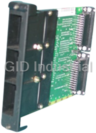
ADC STC-13G

Description
"Tool Strpr Coax
Part Number
STC-13G
Price
Request Quote
Manufacturer
ADC
Lead Time
Request Quote
Category
None
Datasheet

C__Documents and Settings_emily duncan_Local Settings_Application Data_Mozilla_Firefox_Profiles_w5so0idz.pdf
119 KiB

Extracted Text
ADCP-70-043 Issue 2, June 1998 LCC (Little Coaxial Connector) Installation Instructions These instructions provide the information necessary to terminate Little Coaxial Connectors (LCC) on coaxial cable at customer locations. The stripping and crimping tools and accessories needed for each cable type are listed below, and the step-by-step terminating instructions are included in paragraph 2, Installation Procedure. If necessary, refer to the installation drawing (provided in each kit of 25 LCC connectors) for additional illustrations of the tools and the connector parts. 1. TOOLS A. Connection Tool Kit 1.01 The connection tool kit (Catalog Number LCA-600001) for little coaxial connector installation includes the following items: crimp tool (WT-2), 735A die set (LCA-000015), stripping tool with green cassette (STC-13G), cable termination tray (LCA-000009), and connector insertion/withdrawal tool (LCA-400001), in a carrying case. All the tools are illustrated on the next page. 1.02 Table 1 includes the catalog numbers of other crimp die sets and stripping tools used for cable types other than type 735A. ADC recommends the use of either 735A or 0222 mini coaxial cable for equipment cabling to Mini DSX-3 modules. Although larger diameter cables such as RG59 and 734 are available, they are not recommended for use with high density Mini DSX-3 bays due to severe cable congestion that may result. 1.03 As some company practices require the use of specific coaxial stripping tools such as, for example, an automated programmable coaxial stripping machine, check with local company practices to see if any such requirements apply. Table 1. Cable Stripper and Die Set Selection Table CABLE TYPE 735A 0222 RG59 734 Cable Dimensions: Outer Diameter 0.127" 0.155" 0.241" 0.236" Center Conductor 26 gauge 24 gauge 23gauge 20gauge Connector Crimp Dimensions: Sleeve 0.197" 0.197" 0.240" 0.240" Center Pin 0.042" 0.042" 0.042" 0.042" Coaxial Tools: Crimp Tool WT-2 WT-2 WT-2 WT-2 Crimp Die Set LCA-000015 LCA-000010 LCA-000012 LCA-000011 Complete Stripping Tool STC-13G STC-13G STC-12G STC-12G Replacement Cassette CCS-GRN CCS-GRN CCS-GRN CCS-GRN 4-40001-1688 Page 1 © 1998, ADC Telecommunications, Inc. ADCP-70-043 Issue 2, June 1998 B. Tool Illustrations LCC XXXX 10444-A Die Set, LCA-00001X 8345-A Crimp Tool, WT-2 MINIATURE COAXIAL CABLE ADAPTER 8346-B Cable Stripper, STC-13G (or STC-12G) 8347-A Replacement (Green) Cassette, CCS-GRN Page 2 1998, ADC Telecommunications, Inc. LCC XXXX ADCP-70-043 Issue 2, June 1998 8348-A Tightening Wrenches, LCA-000008 3335-B Connector Insertion/Withdrawal Tool, LCA 400001 2. INSTALLATION PROCEDURE Note: Before stripping usable coaxial cable, do several test strips on spare coaxial cable to ensure that the cutting blades of the cable stripper are set to the proper depths. If necessary, adjust the blade depth settings using a thin-blade screwdriver on the rear (memory section) of the cable stripper. Cutting blade adjustments are acceptable when six consecutive test cuts produce acceptable cutting performance. 1. Making sure that the marked end (marked with the “cable type”) goes on first, slide the crimp sleeve onto the coaxial cable. Position the crimp sleeve at least 6 inches (15.3 cm) from the end of the cable, then tape it in place. MARKED END OF CRIMP SLEEVE AWAY FROM CABLE END 8301-B Page 3 1998, ADC Telecommunications, Inc. X X X ADCP-70-043 Issue 2, June 1998 2. Select the proper cable stripper and green cassette (from Table 1). Pull thumb switch away from cutting blades to fully open the cable stripper. If necessary, straighten the end of the cable. For 735A or 0222 mini coaxial cable only, insert the cable adapter between the rollers of the cable stripper, then place the end of the mini coaxial cable between the cable adapter and the green cassette, allowing it to extend about a quarter- inch beyond the body of the cable stripper as shown below: 1/4 IN. SNAP MEMORY LOCK UNIT SNAP LOCK CABLE ADAPTER 8302-C 8635-A When all cables are stripped, remove the cable adapter from between the rollers of the cable stripper, then open the memory unit, slide the cable adapter into its storage position as shown above, then snap the memory unit closed. 3. Advance the thumb switch toward the cutting blades until the cable touches the cutting blades. Holding the cable perpendicular to the stripping tool during the entire stripping process, rotate the stripping tool three times. Advance the thumb switch, again rotating the stripper three times. Repeat this process until the thumb switch cannot be advanced any more; then pull thumb switch all the way back, releasing the coaxial cable from the cutting blades. Cable end should have three separate cuts and should appear as follows: CUTS 8332-A Page 4 1998, ADC Telecommunications, Inc. ADCP-70-043 Issue 2, June 1998 4. The stripper will have cut the outer jacket, the braided shield (and foil shield, if present), and the dielectric. Carefully slide the cut pieces of coaxial layers off the end of the cable, exposing each layer. If the cable has a foil shield under the braided shield, remove equal portions of both shields. CABLE CENTER OUTER DIELECTRIC SHIELD(S) CONDUCTOR JACKET (BEFORE TRIMMING) 8331-A 5. Using the crimping hand tool and the center conductor trimming station on the die set, trim the center conductor to length. The stripped, trimmed cable end should then match the diagram shown below: DIELECTRIC SHIELD CABLE CENTER OUTER CONDUCTOR JACKET CRIMP SLEEVE CRIMPING STATION CENTER CONDUCTOR CENTER CONDUCTOR TRIMMING STATION CRIMPING STATION LCC XXXX .235 REF .200 .47 REF REF 8303-A .670 REF 8333-A 6. Fold back the braided shield; then slide the center pin assembly onto the cable end, over Page 5 1998, ADC Telecommunications, Inc. LCC XXXX XXX ADCP-70-043 Issue 2, June 1998 the foil shield (if present), until it butts against the edge of the outer jacket. Check that the end of the coaxial cable center conductor is visible through the center pin inspection hole in the center pin assembly. FOIL BRAIDED SHIELD SHIELD CABLE CENTER PIN BRAIDED DIELECTRIC ASSEMBLY SHIELD 8343-A CENTER PIN 8304-B INSPECTION HOLE 7. Using the center conductor crimping station on the die set at the cutaway portion of the center pin assembly, crimp the center conductor. The center pin assembly should now be well attached to the center conductor of the coaxial cable. CENTER PIN ASSEMBLY CRIMP 8344-A 8. Fold the braided shield evenly over the end (i.e., ferrule), of the center pin assembly, then slide the crimp sleeve over the braided shield until it butts against the body of the center pin assembly. CABLE BRAIDED CRIMP CENTER PIN SHIELD SLEEVE ASSEMBLY 8305-C Page 6 1998, ADC Telecommunications, Inc. XXX XXX XXX ADCP-70-043 Issue 2, June 1998 9. Using the center (hex) position of the die set, crimp the crimp sleeve onto the braided shield and the ferrule of the center conductor assembly. CRIMPED CRIMPSLEEVE 8306-B 10. Slide the connector shell onto the center pin assembly, and screw down until hand tight. 8334-A 11. Using the two (supplied) tightening wrenches, tighten the connector approximately one- eighth turn (or about 4 to 6 inch-pounds). This completes the installation of the crimp style LCC onto the coaxial cable. 8307-B Completed Installation 12. Perform the following LCC termination tests: a. Visually check that the center conductor is centered in the connector shell and that it remains centered with no movement when you wiggle the cable in back of the connector. Also check that no braid can be seen at the back of the connector. b. Using a DC ohmmeter, test for opens or short-circuits in the cable. Check the cable for end-to-end continuity of (a) the center conductor and (b) the cable shield. Also, check for no continuity between the center conductor and the connector shell. c. Perform a Time Domain Reflectometer (TDR) test by patching a TDR to the front IN and OUT jacks of a DSX module while the newly installed LCC connector is plugged into to the rear of the module. d. Finally, perform a digital signal test. While a DS-3 test set is sending and receiving a set pattern, wiggle the cable at the LCC connector; for a proper connection, the test set will detect no bit errors. Page 7 1998, ADC Telecommunications, Inc. ADCP-70-043 Issue 2, June 1998 4. SYSTEM INTEGRATION SERVICES 4.01 ADC offers the following system integration services. For calls originating in the U.S.A. or Canada, dial 1-800-366-3891, extension 3000. For calls originating outside the U.S.A. or Canada, dial 612-946-3000. Technical Assistance Center • Product Management • Project Engineering • Project Administration • Network Design • Broadband Design (RF Design and Strand Mapping) • Integration Network Testing • Network Monitoring (Upstream or Downstream) • Power Monitoring • Remote Surveillance • System Turn-Up and Test • Service/Maintenance Agreements Technical Training • Product Technology • Custom Designed Training Technical Operations • Detail Engineering • End-to-End Installation • Drafting Services 5. CUSTOMER SUPPORT SERVICES 5.01 ADC offers the following customer support services. For calls originating in the U.S.A. or Canada, dial 1-800-366-3891, then request the extension listed. For calls originating outside the U.S.A. or Canada, dial 612-946-3000. BCG Technical Assistance Center • Technical Information Extension 3475 • System/Network Configuration E-Mail: bcgtac@adc.com • Product Specification • Product Application • Training • Installation and Operation Assistance • Troubleshooting and Repair • Field Assistance Sales Administration • Quotation Proposals Extension 3000 • Ordering • Delivery • General Product Information Product Return Department • ADC Return Authorization number and instructions Extension 3000 must be obtained before returning products. E-Mail: repair&return@adc.com 5.02 Product information and service can also be obtained by writing ADC Telecommunications, Inc., P.O. Box 1101, Minneapolis, Minnesota 55440-1101, U.S.A. Page 8 1998, ADC Telecommunications, Inc. ADCP-70-043 Issue 2, June 1998 Contents herein are current as of the date of publication. ADC reserves the right to change the contents without prior notice. In no event shall ADC be liable for any damages resulting from loss of data, loss of use, or loss of profits and ADC further disclaims any and all liability for indirect, incidental, special, consequential or other similar damages. This disclaimer of liability applies to all products, publications and services during and after the warranty period. This publication may be verified at any time by contacting ADC’s Technical Assistance Center at 1-800-366-3891, extension 3223 (in U.S.A. or Canada) or 612-946-3223 (outside U.S.A. and Canada), or by writing to ADC Telecommunications, Inc., Attn: Technical Assistance Center, Mail Station #77, P.O. Box 1101, Minneapolis, MN 55440-1101, U.S.A. © 1998, ADC Telecommunications, Inc. All Rights Reserved Printed in U.S.A. Page 9
Frequently asked questions
How does Industrial Trading differ from its competitors?

Is there a warranty for the STC-13G?
Which carrier will Industrial Trading use to ship my parts?
Can I buy parts from Industrial Trading if I am outside the USA?
Which payment methods does Industrial Trading accept?









What they say about us
FANTASTIC RESOURCE
One of our top priorities is maintaining our business with precision, and we are constantly looking for affiliates that can help us achieve our goal. With the aid of GID Industrial, our obsolete product management has never been more efficient. They have been a great resource to our company, and have quickly become a go-to supplier on our list!
Bucher Emhart Glass
EXCELLENT SERVICE
With our strict fundamentals and high expectations, we were surprised when we came across GID Industrial and their competitive pricing. When we approached them with our issue, they were incredibly confident in being able to provide us with a seamless solution at the best price for us. GID Industrial quickly understood our needs and provided us with excellent service, as well as fully tested product to ensure what we received would be the right fit for our company.
Fuji
HARD TO FIND A BETTER PROVIDER
Our company provides services to aid in the manufacture of technological products, such as semiconductors and flat panel displays, and often searching for distributors of obsolete product we require can waste time and money. Finding GID Industrial proved to be a great asset to our company, with cost effective solutions and superior knowledge on all of their materials, it’d be hard to find a better provider of obsolete or hard to find products.
Applied Materials
CONSISTENTLY DELIVERS QUALITY SOLUTIONS
Over the years, the equipment used in our company becomes discontinued, but they’re still of great use to us and our customers. Once these products are no longer available through the manufacturer, finding a reliable, quick supplier is a necessity, and luckily for us, GID Industrial has provided the most trustworthy, quality solutions to our obsolete component needs.
Nidec Vamco
TERRIFIC RESOURCE
This company has been a terrific help to us (I work for Trican Well Service) in sourcing the Micron Ram Memory we needed for our Siemens computers. Great service! And great pricing! I know when the product is shipping and when it will arrive, all the way through the ordering process.
Trican Well Service
GO TO SOURCE
When I can't find an obsolete part, I first call GID and they'll come up with my parts every time. Great customer service and follow up as well. Scott emails me from time to time to touch base and see if we're having trouble finding something.....which is often with our 25 yr old equipment.
ConAgra Foods