

 Manufacturers
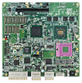
ACROSSER AR-B1652
Description
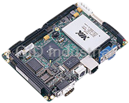
ACROSSER AR-B1652 3.5" SBC powered by VIA Mark Corefusion Processor w/CRT/LCD, 10/100Mbps LAN, PC/104, 4x COM, 2x USB1.1, Stereo, EIDE, CF Type II, SO-DIMM
Part Number
AR-B1652
Price
Request Quote
Manufacturer
ACROSSER
Lead Time
Request Quote
Category
Single Board Computers
Specifications
System Chipset
VIA VT82C686B
VIA Mark CoreFusion Processor+VIA 686B
Form Factor
Mini ITX
Ethernet Chipset
Realtek 8100C
Battery
One time Li-Ion CR2032 220mAh for RTC
BIOS
Award
CPU
VIA Mark 800
Dimensions
145mm X 102mm
Ethernet Connector
RJ45
Ethernet Controller
Realtek RTL8100C (10/100)
Expansion Interface
PCI-104
FSB
133MHz
IDE Interface
One 44-pin IDE connector for HDD
Indicator
Power LED; LAN LED; HDD LED
Memory
One SO-DIMM socket support PC133 SDRAM up to 512MB
Operating Humidity
0 to 90% @ 40oC, non-condensing
Operating Temperature
0~60oC(32~140oF)
OS
Windows XP, XP Embedded, Windows CE and Linux
Power Consumption
Power / HDD LED
Power Mode
AT mode
Power Supply
12V and 5V Dual power,Lockable DC plug-in jacky
Processor
VIA Mark
Serial
RS-232 x 3 RS-232/422/485 x 1
SSD
1 x CompactFlash socket
Storage Temperature
-20~80oC(-4~176oF)
USB
2 x USB 1.1
Video Controller
VIA UniChrome Pro 2D/3D integrated Graphic Controller
Video Interface
VGA port 18-bit LVDS port integrated PWM interface for LCD backlight inverter control
Watchdog Timer
Software programmable 1~255 sec.
Features
- 1 X 10/100 Mbps Ethernet
- 1 X 44 pin E-IDE
- 2 X USB1.1
- 4 X COM
- One SO-DIMM slot
- Stereo (Line-in, Line-out, MIC-In)
- Type II CompactFlash socket
- VGA/LVDS
Datasheet

Extracted Text
AR-B1652 User’s Guide
AR-B1652
3.5” EBC with VIA Mark Processor,
VGA/ LCD/ LVDS/ LAN/ USB
CPU Board
User’ s Guide
Edition: 1.0
Book Number: AR-B1652-06.0906
1
AR-B1652 User’s Guide
Table of Contents
0.PREFACE……………................................................................................................................................................... 3
0.1 COPYRIGHT NOTICE AND DISCLAIMER.....................................................................................................................................3
0.2 WELCOME TO THE AR-B1652 CPU BOARD................................................................................................................................3
0.3 BEFORE YOU USE THIS GUIDE...................................................................................................................................................3
0.4 RETURNING YOUR BOARD FOR SERVICE.................................................................................................................................3
0.5 TECHNICAL SUPPORT AND USER COMMENTS ........................................................................................................................4
0.6 STATIC ELECTRICITY PRECAUTIONS.. ......................................................................................................................................4
1. INTRODUCTION.......................................................................................................................................................... 5
1.1SPECIFICATIONS............................................................................................................................................................................6
1.2 PACKING LIST................................................................................................................................................................................6
2. SETTING UP SYSTEM................................................................................................................................................ 7
2.1 AR-B1652 OVERVIEW....................................................................................................................................................................7
2.2 SYSTEM SETTINGS.......................................................................................................................................................................8
2.2.1 Keyboard & Mouse Connector (KM2).......................................................................................................................................8
2.2.2 SDRAM SOCKET 144 PIN (DIMM1)........................................................................................................................................8
2.2.3 Hard Disk (IDE) Connector (IDE1) ...........................................................................................................................................9
2.2.4 FDD Port Connector (FDD1) ....................................................................................................................................................9
2.2.5 Parallel Port Connector (LPT1) ..............................................................................................................................................10
2.2.6 CRT Connector (VGA1)..........................................................................................................................................................10
2.2.7 USB Connector (USB1)..........................................................................................................................................................10
2.2.8 LVDS Header (LVDS1)...........................................................................................................................................................11
2.2.9 LCD VOLTAGE SELECT (J1) ................................................................................................................................................11
2.2.10 EXTERNAL BUZZER (BZ1) .................................................................................................................................................11
2.2.11 Serial Port (COM1, COM2, COM3, COM4)..........................................................................................................................12
2.2.12 Clear CMOS (JBAT1)...........................................................................................................................................................12
2.2.13 GPIO Port (CN1) ..................................................................................................................................................................13
2.2.14 Touch Screen Connector (TSC1).........................................................................................................................................13
2.2.15 26-Pin Audio Connector (AUDIO1).......................................................................................................................................13
2.2.16 CPU Fan Power Connector (FAN1) .....................................................................................................................................14
2.2.17 LCD Inverter Connector (CN2).............................................................................................................................................14
2.2.18 Infrared Connector (IR1).......................................................................................................................................................14
2.2.19 LED (LED1) ..........................................................................................................................................................................14
2.2.20 Ethernet RJ-45 Connector (LAN1) .......................................................................................................................................15
2.2.21 Reset Button (RST1) ............................................................................................................................................................15
2.2.22 Power Connector (PWR1)....................................................................................................................................................15
2.2.23 PC/104 Connector (PC104)..................................................................................................................................................15
2.2.24 Compact Flash Connector (CF1)..........................................................................................................................................15
2.2.25 CF Master/Salver Connector (J4).........................................................................................................................................16
2.2.26 18-bit LCD Panel Connector (LCD1)....................................................................................................................................16
2.2.27 Battery Connector (BT1).......................................................................................................................................................16
3. WATCHDOG TIMER ................................................................................................................................................. 17
3.1 WATCHDOG TIMER SETTING ....................................................................................................................................................17
3.2 WATCHDOG TIMER TRIGGER....................................................................................................................................................17
4. BIOS CONSOLE........................................................................................................................................................ 18
4.1 BIOS SETUP OVERVIEW.............................................................................................................................................................18
4.2 ADVANCED...................................................................................................................................................................................19
4.3 PERIPHERAL................................................................................................................................................................................20
4.4 PNP/PCI……………………………………………………………………………………………………………………………………….22
4.5 H/W MONITOR..............................................................................................................................................................................23
4.6 BOOT…………………………………………………………………………………………………………………………………………..24
4.7 BIOS EXIT.....................................................................................................................................................................................25
APPENDIX A. MEMORY MAP ...................................................................................................................................... 26
APPENDIX B. INTERRUPT REQUEST (IRQ)............................................................................................................... 27
2
AR-B1652 User’s Guide
0. PREFACE
0.1 COPYRIGHT NOTICE AND DISCLAIMER
This document is copyrighted, 2006, by Acrosser Technology Co., Ltd. All rights are reserved. No part of this
manual may be reproduced, copied, transcribed, stored in a retrieval system, or translated into any language or
computer language in any form or by any means, such as electronic, mechanical, magnetic, optical, chemical,
manual or other means without the prior written permission or original manufacturer.
Acrosser Technology assumes no responsibility or warranty with respect to the content in this manual and
specifically disclaims any implied warranty of merchantability or fitness for any particular purpose. Furthermore,
Acrosser Technology reserves the right to make improvements to the products described in this manual at any
times without notice. Such revisions will be posted on the Internet (WWW.ACROSSER.COM) as soon as possible.
Possession, use, or copy of the software described in this publication is authorized only pursuant to valid written
license from Acrosser or an authorized sub licensor.
ACKNOWLEDGEMENTS
Acrosser, AWARD, IBM PC/AT, VIA, Windows 3.1, MS-DOS…are registered trademarks.
All other trademarks and registered trademarks are the property of their respective owners.
0.2 WELCOME TO THE AR-B1652 CPU BOARD
This guide introduces the Acrosser AR-B1652 CPU Board.
Use information provided in this manual describes this card’s functions and features. It also helps you start, set up
and operate your AR-B1652. General system information can also be found in this publication.
0.3 BEFORE YOU USE THIS GUIDE
Please refer to the Chapter 2, “System Setting,” in this guide, if you have not already installed this AR-B1652.
Check the packing list before you install and make sure the accessories are completely included.
AR-B1652 CD provides the newest information regarding the CPU card. Please refer to the files of the
enclosed utility CD. It contains the modification and hardware & software information, and adding the
description or modification of product function after manual printed.
0.4 RETURNING YOUR BOARD FOR SERVICE
If your board requires any services, contact the distributor or sales representative from whom you purchased the
product for service information. If you need to ship your board to us for service, be sure it is packed in a protective
carton. We recommend that you keep the original shipping container for this purpose.
You can help assure efficient servicing for your product by following these guidelines:
1. Include your name, address, daytime telephone, facsimile number and E-mail.
2. A description of the system configuration and/or software at the time of malfunction.
3. A brief description of the problem occurred.
3
AR-B1652 User’s Guide
0.5 TECHNICAL SUPPORT AND USER COMMENTS
Users comments are always welcome as they assist us in improving the quality of our products and the readability
of our publications. They create a very important part of the input used for product enhancement and revision.
We may use and distribute any of the information you provide in any way appropriate without incurring any
obligation. You may, of course, continue to use the information you provide.
If you have any suggestions for improving particular sections or if you find any errors on it, please send your
comments to Acrosser Technology Co., Ltd. or your local sales representative and indicate the manual title and
book number.
Internet electronic mail to: Sales@acrosser.com
acrosser@tp.globalnet.com.tw
0.6 STATIC ELECTRICITY PRECAUTIONS
Before removing the board from its anti-static bag, read this section about static electricity precautions.
Static electricity is a constant danger to computer systems. The charge that can build up in your body may be more
than sufficient to damage integrated circuits on any PC board. It is, therefore, important to observe basic
precautions whenever you use or handle computer components. Although areas with humid climates are much
less prone to static build-up, it is always best to safeguard against accidents that may result in expensive repairs.
The following measures should be sufficient to protect your equipment from static discharge:
� Touch a grounded metal object to discharge the static electricity in your body (or ideally, wear a grounded
wrist strap).
� When unpacking and handling the board or other system components, place all materials on an anti-static
surface.
� Be careful not to touch the components on the board, especially the “golden finger” connectors on the
bottom of the board.
4
AR-B1652 User’s Guide
1. INTRODUCTION
Welcome to the AR-B1652 Single Board Computer. The AR-B1652 board is EBC board, which VIA Mark
Corefusion Processors with the VIA ® advanced chipset VT82C686B. This product is designed for the system
manufacturers, integrators, or VARs that want to provide all the performance, reliability, and quality at a reasonable
price.
In addition, the AR-B1652 provides on chip VGA. The VGA, which provides up to Ture Color (32 bit) 1024x768.
The VGA memory is share main memory (2M, 4M, or 8M). AR-B1652 also has 18-bit LVDS function in the system.
The AR-B1652 is loaded with special on-board features that rival full-size systems. It has one network controller on
board, uses RealTek RTL8100C LAN controller, a fully integrated 10/100BASE-TX solution with high performance
networking functions. Supports Compact Flash™ Type II interface. Plus optional support for AC97 3D stereo
surround sound with CD-input, AR-B9425A-G (line-in, line-out and speaker-out, microphone). The AR-B1652 also
includes one 144-pin SO-DIMM sockets for up to 512 MB total on-board memory. The AR-B1652 has Four
on-board serial ports; COM1 with RS232C/RS485,COM2 with RS232C share with touch screen COM3/4 with
RS232C, one USB connectors for 2 USB ports, watchdog timer and tough industrial grade construction. All these
features make the AR-B1652 a very "system integrator friendly" solution, perfect for handling applications in the
harshest unmanned environments.
AR-B1652 System Block Diagram
5
AR-B1652 User’s Guide
1.1 SPECIFICATIONS
� CPU: On-board VIA Mark Corefusion Processor 800MHz
� Chipset: VIA ® VT82C686B
� RAM memory: Supports SDRAM PC133, on-board 144-pin SO-DIMM up to 512MB SDRAM memory
module
� VGA Controller: Embedded VGA controller, Screen Resolution: up to Ture Color(32 bit)1024x768.
� Display Interface: CRT – D-SUB 15-pin female connector
LCD –for 18 bit TFT LCD Panel, 2x13x2.0mm pin-header connector
LVDS – DF-13 male connector
� Ultra ATA/33/66/100 IDE Interface: One PCI Enhance IDE channel. The south bridge VT82C686B supports
Ultra ATA/33 IDE interface. To support Ultra ATA66/100 Hard disk, a specified cable must be available.
� Floppy disk drive interface: 2.88 MB, 1.44MB, 1.2MB, 720KB, or 360KB floppy disk drive.
� C. F.: Supports Compact Flash Type II interface
� Series ports: On-board one D-SUB 9-pin male connector for COM1 with RS-232C /RS-485 .On-board one
2x5x2.0mm pin-header connector for COM2 with RS-232C share with Touch Screen
Touch Screen uses 2.0mm 5-pin header connector
� Parallel Port: On-board one 2x13x2.0mm pin-header connector for Parallel port, supports SPP/EPP/ECP
modes
� IrDA port: Supports IrDA (HPSIR) and ASK (Amplitude Shift Keyed) IR port.
� USB port: On-board one 2x4x2.0mm pin-header connector for 2 USB ports
� Audio: onboard AC’97 Codec, On-board one 2x13x2.0mm pin-header for Audio interface Supports two
channel Left/Right Line IN/OUT, and Left/Right speaker out, MIC IN.
� Watchdog timer: Software programmable 1~63sec.
� Ethernet: On-board one Realtek RT8100C, supports 10/100Mbps Base-T with RJ-45 connector.
� K/B & Mouse: On-board PS/2 Keyboard and Mouse connector
� Power Req.: +5V 2.5A and +12V 1A maximum
� PC Board: 8 layers, EMI considered
� Dimensions: 145mm x 102mm (5.7” x 4”)
� Operating Temperature: 0° ~ 60℃
1.2 PACKING LIST
These accessories are included with the system. Before you begin installing your AR-B1652 board, please make
sure that the following items have been included inside the AR-B1652 package.
� The quick setup manual
� 1 AR-B1652 CPU board
� 1 AR-B9425A-G SB Transfer (option)
� 1 AR-B9425A-G Audio Cable (option)
� 2 USB port on one bracket cable (option)
� 1 Had disk adapter (44Pin) (option)
� 1 PS/2 Mouse & Keyboard interface Y-Cable
6
AR-B1652 User’s Guide
2. SETTING UP SYSTEM
This chapter describes how to install the AR-B1652. At first, the layout of AR-B1652 is shown, and the unpacking
information that you should be careful is described.
� Overview
� System Settings
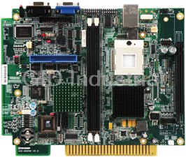
2.1 AR-B1652 OVERVIEW
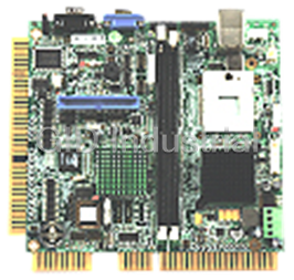
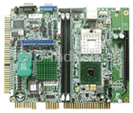
TOP PLACEMENT
BOTTOM PLACEMENT
7
AR-B1652 User’s Guide
2.2 SYSTEM SETTINGS
Jumper pins allow you to set specific system parameters. Set them by changing the pin location of the jumper
blocks. (A jumper block is a small plastic-encased conductor that slips over the pins.) To change a jumper
setting, remove the jumper from its current location with your fingers or small needle-nosed pliers. Place the
jumper over the two pins designated for the desired setting. Press the jumper evenly onto the pins. Be careful
not to bend the pins.
We will show the locations of the AR-B1652 jumper pins, and the factory-default settings.
CAUTION: Do not touch any electronic components unless you are safely grounded. Wear a
grounded wrist strap or touch an exposed metal part of the system unit chassis. The static discharges
from your fingers can permanently damage electronic components.
2.2.1 Keyboard & Mouse Connector (KM2)
The KM2 is a 6-pin Mini DIN keyboard & Mouse connector. This keyboard & Mouse connector is PS/2 type
connector. This connector is also for a standard IBM-compatible keyboard when used with the included PS/2
keyboard & Mouse adapter cable.
2.2.2 SDRAM SOCKET 144 PIN (DIMM1)
It can assemble 16/32/64/128/256/512MB 144 pin DIMM Module Memory. When you set up 144-pin DIMM Module
Memory, AR-B1652 will auto-detect DRAM, and adopt correct save in order to make memory work till the best
situation.
Caution: Set up 144-pin DIMM Module Memory, please insert into slot vertical, if the direction is wrong and it leads
to failure, please confirm the direction is right.
DRAM Configuration (DIMM1)
11144
144 pin SO-DIMM
8
AR-B1652 User’s Guide
2.2.3 Hard Disk (IDE) Connector (IDE1)
44 Pin Hard Disk Connector (IDE1)
The on-board 44-pin mini-pitched IDE interface is used to let user support either a 3.5" HDD with 44 to 40pin
adapter cable.
2 44
1 43
Pin Signal Pin Signal
1 -RESET 2 GROUND
3 DATA 7 4 DATA 8
5 DATA 6 6 DATA 9
7 DATA 5 8 DATA 10
9 DATA 4 10 DATA 11
11 DATA 3 12 DATA 12
13 DATA 2 14 DATA 13
15 DATA 1 16 DATA 14
17 DATA 0 18 DATA 15
19 GROUND 20 Not Used
21 IDEDREQ 22 GROUND
23 -IOW A 24 GROUND
25 -IOR A 26 GROUND
27 IDEIORDYA 28 GROUND
29 -DACKA 30 GROUND
31 AINT 32 Not Used
33 SA 1 34 Data33_66
35 SA 0 36 SA 2
37 CS 0 38 CS 1
39 HD LED A 40 GROUND
41 VCC 42 VCC
43 GROUND 44 Not Used
2.2.4 FDD Port Connector (FDD1)
The AR-B1652 provides a 34-pin header type connector for supporting up to two floppy disk drives. To enable
or disable the floppy disk controller, please use the BIOS Setup program.
2 34
1 33
Pin Signal Pin Signal
1-33(odd) GROUND 18 -DIRECTION
2 DRVEN 0 20 -STEP OUTPUT PULSE
4 NOT USED 22 -WRITE DATA
6 DRVEN 1 24 -WRITE ENABLE
8 -INDEX 26 -TRACK 0
10 -MOTOR ENABLE 0 28 -WRITE PROTECT
12 -DRIVE SELECT 1 30 -READ DATA
14 -DRIVE SELECT 0 32 -SIDE 1 SELECT
16 -MOTOR ENABLE 1 34 DISK CHANGE
9
AR-B1652 User’s Guide
2.2.5 Parallel Port Connector (LPT1)
The connector for the parallel port is a 26-pin header connector.
2 26
1 25
Parallel Port Connector
DB-25 Signal DB-25 Signal
1 -Strobe 14 -Auto Form Feed
2 Data 0 15 -Error
3 Data 1 16 -Initialize
4 Data 2 17 -Printer Select In
5 Data 3 18 Ground
6 Data 4 19 Ground
7 Data 5 20 Ground
8 Data 6 21 Ground
9 Data 7 22 Ground
10 -Acknowledge 23 Ground
11 Busy 24 Ground
12 Paper 25 Ground
13 Printer Select 26 No Used
2.2.6 CRT Connector (VGA1)
VGA1 is a standard 15-pin D-SUB connector commonly used for VGA.
2.2.7 USB Connector (USB1)
The Universal Serial Bus (USB) controller is USB V1.1 and Universal HCI V1.1 compliant. The Universal Serial
Bus (USB) standard is a low-to-medium speed interface for the connection of PC peripherals, which gives
complete Plug & Play, and hot attach/detach for up to 127 external devices.
USB is a leading edge technology that allows the user to quickly and easily add a wide range of peripheral devices
from printers to keyboards and telephony devices to fax/modems. Universal Host Controller Interface (UHCI) and
future support for the Open Host Controller Interface (OHCI) ensure USB compatibility and usability well into the
future.
The CPU board supports four Universal Serial Bus ports. An optional external port bracket attaches to the onboard
connector via an attached cable. With the optional port bracket installed you can attach USB devices to the
external ports. If the USB ports are installed, the USB Controller line in the Integrated Peripherals section of the
CMOS Setup utility must be set to “Enabled”. USB ports may also require Operating System support for USB
devices.
10
AR-B1652 User’s Guide
USB1 use an adapter cable to interface with external equipment.
2.2.8 LVDS Header (LVDS1)
2.2.9 LCD VOLTAGE SELECT (J1)
2.2.10 EXTERNAL BUZZER (BZ1)
11
AR-B1652 User’s Guide
2.2.11 Serial Port (COM1, COM2, COM3, COM4)
� AR-B1652 is equipped with four serial ports. COM1 is a standard RS-232 interface.
� COM2/3/4 use an adapter cable to interface with external equipment.
� When we are configuring J3 and J5, COM1 can also be configured as an RS-232, RS-485 or RS-422 port.
A. COM1
USED RS232 & RS485 & RS422
COM1
1
6
2
7
3
8
4
9
5
J3 J5
B. COM2/3/4
USED RS232
2.2.12 Clear CMOS (JBAT1)
12
AR-B1652 User’s Guide
2.2.13 GPIO Port (CN1)
2.2.14 Touch Screen Connector (TSC1)
TSC1 is a serial port, which is parallel with COM2. It provides another choice when user needs a serial port but
need to connect from board directly without connecting through a D-type connector. The typical application is a
touch screen panel.
2.2.15 26-Pin Audio Connector (AUDIO1)
Note: the connector does not contain the GAME (MIDI) port signal. When AR-B1652 audio card is used with
this CPU board, the GAME port function is not supported.
13
AR-B1652 User’s Guide
2.2.16 CPU Fan Power Connector (FAN1)
FAN1 is 3-pin header for the CPU fan. The fan must be a 12V fan.
2.2.17 LCD Inverter Connector (CN2)
PIN Signal
1 +12V
2 +12v
3 GND
4 ENVEE
5 GND
6 GND
2.2.18 Infrared Connector (IR1)
The Infra-red Header pin assignment is as follows:
1.VCC
2.NC
1 5 3.IR DATA RECEIVER
4.GND
5.IR DATA TRANSFER
2.2.19 LED (LED1)
Power LED: External LED connector for Watchdog status indication.
LAN LED: External LED connector for 10/100M LAN
HDD LED (IDE1): External LED connector for primary IDE channel.
14
AR-B1652 User’s Guide
2.2.20 Ethernet RJ-45 Connector (LAN1)
The system supports onboard network connectivity. To utilize this function, install the network driver from the
utility diskette, and connect the cable to the following RJ-45 header.
2.2.21 Reset Button (RST1)
SW
1 2
SW PUSHBUTTON
2.2.22 Power Connector (PWR1)
The PWR1 is a 4-pin power connector. It’s the standard connector on all Acrosser boards.
2.2.23 PC/104 Connector (PC104)
(1) 64 Pin PC/104 Connector A&B
2 64
63
1
(2) 40 Pin PC/104 Connector C&D
2 40
39
1
Note:
If the content in setting is inconsistent with the CD-ROM, please refer to the setting as the priority.
15
AR-B1652 User’s Guide
2.2.24 Compact Flash Connector (CF1)
2.2.25 CF Master/Salver Connector (J4)
2.2.26 18-bit LCD Panel Connector (JCD1)
2.2.27 Battery Connector (BT1)
16
AR-B1652 User’s Guide
3. WATCHDOG TIMER
This section describes the use of Watchdog Timer, including disable, enable, and trigger. AR-B1652 is equipped
with a programmable time-out period watchdog timer that occupies I/O port 443H. Users can use simple program to
enable the watchdog timer. Once you enable the watchdog timer, the program should trigger it every time before it
times out. Watchdog Timer will generate a response (system or IRQ) due to system fails to trigger or disable
watchdog timer before preset timer, times out.
Time Base
Enable(D7)
Time Factor
(D0-D5) Watchdog
Register
Counter and
Write and
Compartor
Trigger
RESET
Watchdog Block Diagram
3.1 WATCHDOG TIMER SETTING
The watchdog timer is a circuit that maybe be used from your program software to detect crash or hang up.
The Watchdog timer is automatically disabled after reset. Once you enabled the watchdog timer, your program
should trigger the watchdog timer every time before it times out. After you trigger the watchdog timer, the timer will
be set to zero and start to count again. If your program fails to trigger the watchdog timer before times out, it will
generate a reset pulse to reset the system or trigger the IRQ 9 signal in order to tell your system that the watchdog
time is out.
Please refer to the following table in order to properly program Watchdog function
D7 D6 D5 D4 D3 D2 D1 D0
1 Enable Reset Time period
0 Disable IRQ 9
Users could test watchdog function under ‘Debug’ program as follows:
C:>debug
� O 443 C8H
Generally, watchdog function would reset system after 8 seconds
� O 443 0H
Disable watchdog function
C:>debug
� O 443 88H
Generally, watchdog function would generate IRQ 9 after 8 seconds
� O 443 0H
Disable watchdog function
3.2 WATCHDOG TIMER TRIGGER
After you enable the watchdog timer, your program must write the same factor as triggering to the watchdog timer
at least once during every time-out period. You can change the time-out period by writing another timer factor to the
watchdog register at any time, and you must trigger the watchdog during every new time-out period in next trigger.
17
AR-B1652 User’s Guide
4. BIOS CONSOLE
This chapter describes the AR-B1652 BIOS menu displays and explains how to perform common tasks needed to
get up and running, and presents detailed explanations of the elements found in each of the BIOS menus. The
following topics are covered:
� BIOS Setup Overview
� Advanced CMOS Setup
� Peripheral Setup
� Boot
� BIOS Exit
4.1 BIOS SETUP OVERVIEW
The BIOS is a program used to initialize and set up the I/O system of the computer, which includes the
ISA bus and connected devices such as the video display, diskette drive, and the keyboard.
The BIOS provides a menu-based interface to the console subsystem. The console subsystem
contains special software, called firmware that interacts directly with the hardware components and
facilitates interaction between the system hardware and the operating system.
The BIOS default values ensure that the system will function at its normal capability. In the worst
situation the user may have corrupted the original settings set by the manufacturer.
After the computer is turned on, the BIOS will perform diagnostics on the system and display the size of
the memory that is being tested. Press the [Del] key to enter the BIOS Setup program, and then the
main menu will show on the screen.
The BIOS Setup main menu includes some options. Use the [Up/Down] arrow key to highlight the
option that you wish to modify, and then press the [Enter] key to select the option and configure the
functions.
Setup Main Menu
The
Frequently asked questions
How does Industrial Trading differ from its competitors?

Is there a warranty for the AR-B1652?
Which carrier will Industrial Trading use to ship my parts?
Can I buy parts from Industrial Trading if I am outside the USA?
Which payment methods does Industrial Trading accept?
Why buy from GID?

Quality
We are industry veterans who take pride in our work

Protection
Avoid the dangers of risky trading in the gray market

Access
Our network of suppliers is ready and at your disposal

Savings
Maintain legacy systems to prevent costly downtime

Speed
Time is of the essence, and we are respectful of yours
Related Products
Request a Quote

The quote request has been received
Close

Facing challenges or have inquiries? Feel free to contact us!
Call Us +1-469-283-2440
What they say about us
FANTASTIC RESOURCE
One of our top priorities is maintaining our business with precision, and we are constantly looking for affiliates that can help us achieve our goal. With the aid of GID Industrial, our obsolete product management has never been more efficient. They have been a great resource to our company, and have quickly become a go-to supplier on our list!
Bucher Emhart Glass
EXCELLENT SERVICE
With our strict fundamentals and high expectations, we were surprised when we came across GID Industrial and their competitive pricing. When we approached them with our issue, they were incredibly confident in being able to provide us with a seamless solution at the best price for us. GID Industrial quickly understood our needs and provided us with excellent service, as well as fully tested product to ensure what we received would be the right fit for our company.
Fuji
HARD TO FIND A BETTER PROVIDER
Our company provides services to aid in the manufacture of technological products, such as semiconductors and flat panel displays, and often searching for distributors of obsolete product we require can waste time and money. Finding GID Industrial proved to be a great asset to our company, with cost effective solutions and superior knowledge on all of their materials, it’d be hard to find a better provider of obsolete or hard to find products.
Applied Materials
CONSISTENTLY DELIVERS QUALITY SOLUTIONS
Over the years, the equipment used in our company becomes discontinued, but they’re still of great use to us and our customers. Once these products are no longer available through the manufacturer, finding a reliable, quick supplier is a necessity, and luckily for us, GID Industrial has provided the most trustworthy, quality solutions to our obsolete component needs.
Nidec Vamco
TERRIFIC RESOURCE
This company has been a terrific help to us (I work for Trican Well Service) in sourcing the Micron Ram Memory we needed for our Siemens computers. Great service! And great pricing! I know when the product is shipping and when it will arrive, all the way through the ordering process.
Trican Well Service
GO TO SOURCE
When I can't find an obsolete part, I first call GID and they'll come up with my parts every time. Great customer service and follow up as well. Scott emails me from time to time to touch base and see if we're having trouble finding something.....which is often with our 25 yr old equipment.
ConAgra Foods