

 Manufacturers
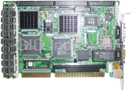
AAEON SBC-776

Description
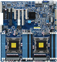
Full-sized Intel FC-370 Pentium III CPU Card with Intel 815E chipset, Dual LAN, Audio, SCSI, LCD & 4 USB
Part Number
SBC-776
Price
Request Quote
Manufacturer
AAEON
Lead Time
Request Quote
Category
Single Board Computers
Specifications
System Chipset
Intel 815E
Form Factor
PICMG 1.0
Datasheet

Extracted Text
SBC-776
Full-sized Intel FC-370 Pentium III CPU
Card with Intel 815E chipset, Dual LAN,
Audio, SCSI, LCD & 4 USB.
Copyright Notice
This document is copyrighted, 2001. All rights are reserved. The
original manufacturer reserves the right to make improvements to
the products described in this manual at any time without notice.
No part of this manual may be reproduced, copied, translated, or
transmitted in any form or by any means without the prior written
permission of the original manufacturer. Information provided in
this manual is intended to be accurate and reliable. However, the
original manufacturer assumes no responsibility for its use, nor for
any infringements upon the rights of third parties which may result
from its use.
The material is this document is for product information only and is
subject to change without notice. While reasonable efforts have
been made in the preparation of this document to assure its
accuracy, AAEON, assumes no liabilities resulting from errors or
omissions in this document, or from the use of the information
contained herein.
AAEON reserves the right to make changes in the product design
without notice to its users.
Part No. 2047776000 SBC-776 1st. Edition
Printed in Taiwan May., 2001
Acknowledgments
All other product names or trademarks are properties of their
respective owners.
AMD is a trademark of Advanced Micro Devices, Inc.
AMI is a trademark of American Megatrends, Inc.
Award is a trademark of Award Software International, Inc.
IBM, PC/AT, PS/2, and VGA are trademarks of International
Business Machines Corporation.
Intel and Pentium III are trademarks of Intel Corporation.
®
Microsoft Windows is a registered trademark of Microsoft Corp.
SMC is a trademark of Standard Microsystems Corporation.RTL is
a trademark of Realtek Semi-Conductor Co., Ltd.
C&T is a trademark of Chips and Technologies, Inc.
UMC is a trademark of United Microelectronics Corporation.
ITE is a trademark of Integrated Technology Express, Inc.
SiS is a trademark of Silicon Integrated Systems Corp.
VIA is a trademark of VIA Technology, Inc.
A Message to the Customer
AAEON Customer Services
Each and every AAEON product is built to the most exacting
specifications to ensure reliable performance in the harsh and
demanding conditions typical of industrial environments. Whether
your new AAEON equipment is destined for the laboratory or the
factory floor, you can be assured that your product will provide the
reliability and ease of operation for which the name AAEON has
come to be known.
Your satisfaction is our primary concern. Here is a guide to
AAEON's customer services. To ensure you get the full benefit of
our services, please follow the instructions below carefully.
Technical Support
We want you to get the maximum performance from your products.
So if you run into technical difficulties, we are here to help. For the
most frequently asked questions, you can easily find answers in
your product documentation. These answers are normally a lot
more detailed than the ones we can give over the phone.
So please consult this manual first. If you still cannot find the
answer, gather all the information or questions that apply to your
problem, and with the product close at hand, call your dealer. Our
dealers are well trained and ready to give you the support you need
to get the most from your AAEON products. In fact, most problems
reported are minor and are able to be easily solved over the phone.
In addition, free technical support is available from AAEON
engineers every business day. We are always ready to give advice
on application requirements or specific information on the installa-
tion and operation of any of our products.
Product Warranty
AAEON warrants to you, the original purchaser, that each of its
products will be free from defects in materials and workmanship for
two years from the date of shipment.
This warranty does not apply to any products which have been
repaired or altered by persons other than repair personnel autho-
rized by AAEON, or which have been subject to misuse, abuse,
accident or improper installation. AAEON assumes no liability
under the terms of this warranty as a consequence of such events.
Because of AAEON's high quality-control standards and rigorous
testing, most of our customers never need to use our repair service.
If an AAEON product is defective, it will be repaired or replaced at
no charge during the warranty period. For out-of-warranty repairs,
you will be billed according to the cost of replacement materials,
service time, and freight. Please consult your dealer for more
details.
If you think you have a defective product, follow these steps:
1. Collect all the information about the problem encountered. (For
example, CPU type and speed, AAEON products used, other
hardware and software used, etc.) Note anything abnormal and
list any on-screen messages you get when the problem occurs.
2. Call your dealer and describe the problem. Please have your
manual, product, and any helpful information readily available.
3. If your product is diagnosed as defective, obtain an RMA
(return material authorization) number from your dealer. This
allows us to process your return more quickly.
4. Carefully pack the defective product, a fully-completed Repair
and Replacement Order Card and a photocopy proof of pur-
chase date (such as your sales receipt) in a shippable container.
A product returned without proof of the purchase date is not
eligible for warranty service.
5. Write the RMA number visibly on the outside of the package
and ship it prepaid to your dealer.
Packing list
Before you begin installing your card, please make sure that the
following materials have been shipped:
• 1 SBC-776 Half- size Single Board Computer Card
• 1 Quick Installation Guide
• 1 Support CD contains the followings:
-- User's Manual (this manual in PDF file)
-- Ethernet driver and utilities
-- VGA driver and utilities
-- Audio driver and utilities
• 1 floppy disk drive interface cable (34-pin, pitch 2.0mm)
• 1 IDE hard disk drive cable (40-pin, pitch 2.54mm)
• 1 parallel port (26-25-pin, pitch 2.0mm) and serial port (10-9 pin,
pitch 2.0mm) adapter kit.
• 1 bag of screws and miscellaneous parts
If any of these items are missing or damaged, contact your distribu-
tor or sales representative immediately.
Notice
Dear Customer,
Thank you for purchasing the SBC-776 board. This user's
manual is designed to help you to get the most out of the SBC-776,
please read it thoroughly before you install and use the board. The
product that you have purchased comes with an two-year limited
warranty, but AAEON will not be responsible for misuse of the
product. Therefore, we strongly urge you to first read the manual
before using the product.
To receive the latest version of the user manual, please visit our
Web site at:
Http:\\WWW.AAEON.COM
http://www.aaeon.com
Contents
Chapter 1: General Information.........................................1
Introduction.......................................................2
Features.................................................................................... 3
Specifications ........................................................................... 4
Board layout ............................................................................. 7
Board dimensions ..................................................................... 8
Chapter 2: Installation .......................................................... 9
Safety Precautions...........................................................10
Removing the CPU..................................................10
Installing the CPU............................................................... 11
Installing SDRAM...................................................12
Jumpers..............................................................13
Connectors ..............................................................................14
Locating Jumpers and Connectors............................................15
Mechanical Drawing................................................17
VGA or AGP VGA Header Select (JP1).................................19
Clear CMOS (JP2) .................................................................19
Watchdog Timer (JP3) ............................................................20
COM2 RS-232/422/485 Setting (JP4)......................................21
DiskOnChip Address Select (JP5).................................... ..22
Function Select Header (JP6) .................................................24
CPU/DIMM Speed Select Header (JP7) ...............................25
LCD Panel's Voltage Setting (JP8) ....................................... 27
COM2 RS-232/422/485 Setting (JP4) ..................................... 28
LCD or VGA Enable Header (JP10) .....................................29
VGA Connector (CN6)...........................................................29
IDE Hard Drive Connector (CN7) .........................................30
USB Connector (CN9, CN10)...............................31
Audio Connector (CN11) ........................................................ 32
Floppy Drive Connector (CN12).........................................33
PS/2 Keyboard and Mouse Connector(CN13) .......................33
Parallel Port Connector (CN14)..............................................34
COM1 & COM2 Serial Port (CN15, CN16)..........................35
SCSI Connector (CN21) .........................................................36
100Base-Tx Fast Ethernet Connector (CN22, CN20) ............37
ATX Power Connector (CN23)..............................38
Speaker/BuzzerConnector (CN24)..........................38
Fan Power Connector (CN25, CN26, CN27)...........................39
LCD Backlight Power Connector (CN28)...............40
TFT LCD Panel Connector (CN29)......................40
PS/2 Keyboard Header (CN31)............................41
PS/2 Mouse Header (CN32)................................41
Chapter 3: Award BIOS Setup...........................................42
Starting setup..................................................................43
Setup keys.......................................................................44
Getting help ......................................................................... 45
Main setup menu .....................................................................46
Standard CMOS setup ............................................................48
Advanced BIOS features........................................................53
Advanced CHIPSET features ................................................58
Integrated Peripherals...............................................61
Power management setup .......................................................67
PNP/PCI congfiguration setup ................................................72
PC Health Status......................................................74
Frequency/Voltage Control........................................75
Load Fail-Safe Defaults............................................76
Load Optimized Defaults..........................................77
Set Supervisor Password.......................................78
Set User Password...............................................79
Save and Exit Setup............................................80
Exit & Save......................................................81
Chapter 4: Drivers and Utilities .......................................82
Installing Drivers Attention Notice....................................83
Software Installation Utilities........................................85
Intel 82562ET LAN Driver............................................86
Advansys 38C0800 SCSI Driver............................................89
Intel 82559ER LAN Driver...........................................91
VGA Driver...............................................................93
Ultra ATA Storage Driver................................................94
Audio Driver............................................................95
1
General
Information
This chapter gives background
information of the mainboard.
Sections Include:
• Board Specifications
• Layout and Dimensions
Chapter 1 General Information 1
CHAPTER
Introduction
The SBC-776 is an all-in-one Single Board Computer (SBC) capable
of handling the Intel Celeron 300~766MHz (with system bus
frequencies of 66MHz) and Pentium III 500~850 MHz (with system
bus frequencies of 100MHz). Reliability, performance, flexibility are
essential qualities for SBC's and SBC-776 offers all of these.
Onboard is the versatile Intel 815E chipset, controlling LAN, LCD,
and AUDIO. The VGA has a display memory size of 4 MB, with
resolutions up to 1024 x 768 at 256K. Ethernet connections can be
easily carried out through two RJ-45 connectors.
This full-sized SBC supports M-Systems DiskOnChip 2000 family
of flash disk products that are small, plug and play, solid state disks
in a standard 32-pin DIP package with capabilities ranging from
8MB to 288MB. There are also three 168-pin DIMM sockets
providing a maximum of 512MB. A compact flash connector is
provided on the solder side of the board.
The additional Advansys ASC38C0800, Ultra II Wide SCSI coordi-
nates up to 15 devices that are simultaneously connected to your
mainboard. Connection with the onboard chipset is made through
a 68-pin SCSI connector.
SBC-776 supports two IDE devices, two floppy disks, four USB
ports, two serial ports that can be configured as COM1, COM2,
COM3 and COM4. The single bidirectional parallel port can
support SPP, ECP and EPP modes. The standard ATX power
connector enables this full-sized SBC to be operated without any
backplane if necessary.
2 SBC-776 User Manual
Features
• Supports Intel Celeron /Pentium III FC-370 CPUs
• High Speed AGP 2X for VGA function onboard
(Intel 815E built in)
• Two 10/100 Base-T Fast Ethernet (Intel 815 E built in and Intel 82559ER)
• Supports H/W status monitoring
• Integrated AC-97 2.1 SoundBlaster compatible PCI 3D Audio
• Onboard Intel 815E controller supports 18/36-bit TFT panel
• Supports Compact Flash Memory
• Four USB ports onboard
• Two COM ports onboard
• Ultra II Wide SCSI interface onboard
• Supports DiskOnChip
Chapter 1 General Information 3
Specifications
Standard LPX-size SBC functions
• CPU: FC-370 Pentium III (Coppermine), Celeron, and compatible CPUs
(With system bus frequencies of 66/100/133MHz).
• CPU socket: Intel Socket 370
• Bus interface: PICMG Compliant
• BIOS: Award 4 MB Flash BIOS
• Chipset: Intel 815E
• I/O chipset: Winbond W83627HF. Fully 16-bit I/O decoded
• ISA bus interface: Winbond W83626 LPC to ISA bridge Full ISA bus
function except master mode support
• Memory : Onboard three 168 pins DIMM socket supports up to
512Mbytes SDRAM (PC-133 SDRAM supported).
• Enhanced IDE: Supports two IDE channel. Support Ultra DMA/ 100
mode with data transfer rate of 100MB/sec.
• FDD interface: Supports two floppy disk drives, 5.25" (360KB and
1.2MB) and/or 3.5" (720KB, 1.44MB, and 2.88MB).
• Parallel port: One bi-directional parallel ports. Supports SPP, ECP, and
EPP modes.
• Serial port: One RS-232 and one RS-232/422/485 serial port. Ports can be
configured as COM1, COM2, COM3, COM4, or disabled individually
and of which one and be configured as RS-232/422/485 (COM2).
(16C550 equivalent).
• KB/Mouse connector : 6-pin mini-DIN connector supports PC/AT
keyboard and PS/2 mouse and wake on KBD function.
• USB connectors: 10-pin onboard connector supports four USB ports.
• Battery: Lithium battery for data retention
• Watchdog timer: Can generate a system reset, IRQ15, or NMI.
Software selectable time-out interval (1 sec. ~ 255 min., 1 sec./step or
1 min./step)
• DMA: 7 DMA channels (8237 equivalent)
4 SBC-776 User Manual
• Interrupt: 15 interrupt levels (8259 equivalent)
• Power management: Supports ATX power supply. I/O peripheral
support power saving and doze/standby/suspend modes. APM 1.2
compliant.
• H/W status monitoring: Embedded in W83267HF supports power,
supply voltages, and temperature monitoring.
Flat Panel/CRT Interface
• Chipset: embedded In Intel 815E
• Chipset output VGA signal: AGP 4X
• Display memory: Share system memory 4MB SDRAM (Max)
• Display type: Supports non-interlaced CRT and up to 18/36 bit LCD (TFT,
LCD, only). Can display both CRT and Flat Panel simultaneously.
• Resolution: Up to 1024 x 768 @ 256 K colors
Audio Interface
• Chipset: Intel 815E
• Audio interface: One 14 pin header (2.00mm)
• Codec: ALC 200
Ethernet Interface
• Chipset: Intel 815E embedded in ICH2 and Intel 82559ER
• Ethernet interface : 82559ER does not support WOL and AOL
82562ET support WOL and do not support AOL
82562EM support WOL and AOL. 776 offers 82559ER and 82562 ET on
board.
Compact Flash socket onboard
• Compact flash connector onboard support type 2 CFD
Chapter 1 General Information 5
Ultra Wide II SCSI Interface
• Chipset: AdvanSys ASC38C0800
• Connector: 68-pin internal
• Termination: Auto termination
SSD Interface
• One 32-pin DIP socket supports M-Systems DiskOnChip 2000 series
Mechanical and environmental
• Power supply voltage: ATX power supply
o o
• Operating temperature: 32 to 140 F (0 to 60 C)
• Board size: 13.3"(L) x 4.8"(W) (338mm x 122mm)
• Weight: 1.2 lb. (0.3 Kg)
6 SBC-776 User Manual
CN23
JP6
CN25
CN27
CN15
CN34
CN14
CN16
CN6
CN20
CN22
CN13
CN31
CN26
Board Layout
CN24
JP7
CN2
CN3
CN4
JP10
CN7
CN5
JP1
CN12
JP2
JP8
CN28
CN29
CN9
CN30
CN10
JP5
CN33
JP9
JP3
JP4
CN21
CN11
CN32
Chapter 1 General Information 7
Winbond
W83977F-A
Board Dimensions
8 SBC-776 User Manual
Winbond
W83977F-A
2
Installation
This chapter describes how to set up the
main board hardware, including instruc-
tions on setting jumpers and connecting
peripherals, switches, and indicators. Be
sure to read all the safety precautions
before you begin the installation proce-
dure.
SBC-776 Chapter 2 9
CHAPTER
SBC-776
Safety precautions
Warning! Always completely disconnect the power cord from
your chassis whenever you are working on it. Do
not make connections while the power is on
because sensitive electronic components can be
damaged by the sudden rush of power. Only
experienced electronics personnel should open the
PC chassis.
Caution! Always ground yourself to remove any static charge
before touching the CPU card. Modern electronic
devices are very sensitive to static electric charges.
Use a grounding wrist strap at all times. Place all
electronic components on a static-dissipative surface
or in a static-shielded bag when they are not in the
chassis.
Removing the CPU
The SBC-776 all-in-one CPU module supports most Pentium III/
Celeron or 586 CPUs. The system's performance depends on the
CPU you choose. You can install or upgrade the CPU in the board's
PGA socket by following the procedures outlined below. If your
system has an existing CPU, you need to remove it before installing
the new CPU.
Removing a CPU
1. Disconnect power from the chassis, and unplug all connections
to the CPU card. Then, remove the CPU card from the chassis
by following the instructions in the user's manual for your
chassis.
2. Lift the CPU out of the PGA socket. The old chip may be
difficult to remove. You may find spray chip lubricant, designed
for pin-grid-array (PGA) devices, and a chip puller helpful.
These are available at electronics hobbyists' supply stores.
10 SBC-776 ManualBC-599/596
Installing A CPU
To install the CPU, follow the instructions that came with it. If no
documentation was provided, the general procedures for installing
a CPU are outlined below:
1. Lubricate the pins on the CPU with lubricant for PGA devices.
This makes the CPU slide in much easier and greatly reduces
the chance of damaging the pins and other components.
2. Carefully align the CPU so that it is parallel to the socket. Make
sure that the notch on the corner of the CPU matches the notch
on the inside of the socket.
3. Gently push the CPU into the socket. There will probably be a
small gap between the CPU and the socket even when it is fully
seated. DO NOT USE EXCESSIVE FORCE!
When you install a new CPU, you may have to adjust other
settings on the board, such as CPU type, CPU clock, and PCI
speed, to accommodate it. Make sure that the settings are correct
for your CPU. Improper settings may damage the CPU.
SBC-776 Chapter 2 11
SBC-776
Installing DRAM (DIMMs)
System Memory
The SBC-776 contains three sockets for 168-pin dual inline memory
module (DIMM). The socket uses 3.3 V unbuffered synchronous
DRAM (SDRAM). DIMM is available in capacities of 16, 32, 64, 128
or 256 MB. The socket can be filled in the DIMM of any size,
giving your SBC-776 single board computer between 16 and 512
MB of memory.
Supplementary information about DIMM
SBC-776 can accept PC-133 SDRAM DIMM Module(with or
without parity).
Single-sided modules are typically 16 or 64 MB; double-sided
modules are usually 32, 128 or 256 MB.
Memory Installation Procedures
To install DIMM, first make sure the two handles of the DIMM
socket are in the "open" position. i.e. The handles remain outward.
Slowly slide the DIMM module along the plastic guides on both
ends of the socket. Then press the DIMM module right down into
the socket, until you hear a click. This is when the two handles
have automatically locked the memory module into the correct
position of the DIMM socket. (See Figure below) To take away the
memory module, just push both handles outward, and the memory
module will be ejected by the mechanism in the socket.
12 SBC-776 ManualBC-599/596
Jumpers
Jumpers Function
JP1 VGA or AGP VGA Select Header
JP2 Clear CMOS Selection
JP3 Watchdog Function Select
JP4 RS-232/422/485 COM 2 Setting
JP5 DiskOnChip Address Selection
JP6 Function Select
JP7 CPU/DIMM Speed Select
JP8 LCD Panel's Voltage Setting
JP9 RS-232/422/485 COM2 Setting
JP10 LCD or VGA Enable Header
SBC-776 Chapter 2 13
SBC-776
Connectors
Connector Function
CN2,3,4 SDRAM Slot
CN5 AGP Slot
CN6 VGA Connector
CN7 Primary IDE Connector
CN8 Compact Flash
CN9,10 USB Dual Port Header
CN11 Audio Connector
CN12 Floppy Drive Connector
CN13 PS/2 Keyboard and Mouse Connector
CN14 Parallel Port Connector
CN15 COM 1 Serial Port
CN16 COM 2 Serial Port
CN20,22 LAN RJ-45 Connector
CN21 SCSI Connector
CN23 ATX Power Supply
CN24 Speaker/Buzzer
CN25 System FAN 1 Connector
CN26 CPU Fan Connector
CN27 System FAN 2 Connector
CN28 LCD Backlight Power Connector
CN29 TFT LCD Panel Connector
CN31 PS/2 Keyboard Header
CN32 PS/2 Mouse Header
14 SBC-776 ManualBC-599/596
CN23
JP6
CN25
CN27
CN15
CN34
CN14
CN16
CN6
CN20
CN22
CN13
CN31
CN26
Locating Jumpers and Connectors
CN24
JP7
CN2
CN3
CN4
JP10
CN7
CN5
JP1
CN12
JP2
JP8
CN28
CN29
CN9
CN30
CN10
JP5
CN33
JP9
JP3
JP4
CN21
CN11
CN32
SBC-776 Chapter 2 15
Win bond
W 83977F-A
SBC-776
Locating Jumpers and Connectors
CN8
16 SBC-776 ManualBC-599/596
Mechanical Drawing
SBC-776 Chapter 2 17
Win bond
W 83977F-A
SBC-776
Mechanical Drawing
18 SBC-776 ManualBC-599/596
VGA or AGP VGA Header Select (JP 1)
Select AGP VGA
1 2
3 4
5 6
7 8
9 10
11 12
13 14
Select on board VGA
1 2
3 4
5 6
7 8
9 10
11 12
13 14
Clear CMOS (JP2)
You can use JP2 to clear the CMOS data if necessary. To reset the
CMOS data, place a jumper on JP2 for just a few seconds, then
remove the jumper.
Clear CMOS (J2P)
Clear CMOS Protect*
1 2 3
1 2 3
JP2
*default
SBC-776 Chapter 2 19
SBC-776
Watchdog Timer Function Select (JP3)
The mainboard is equipped with a watchdog timer that resets the CPU
or generates an interrupt if processing comes to a standstill for whatever
reason. This feature ensures system reliability in industrial stand-alone
and unmanned environments.
Reset
1 2
3 4
5 6
IRQ15
1 2
3 4
5 6
NMI
1 2
3 4
5 6
20 SBC-776 ManualBC-599/596
RS-232/422/485 COM 2 (JP4 & JP9) Setting
The SBC-776 COM 2 serial port can be selected as RS-232/422/485 by
setting JP4.
*RS-232
3 6 9 12
2 4 6
1 3 5
1 4 7 10
*RS-485
3 6 9 12
2 4 6
1 3 5
1 4 7 10
*RS-422
3 6 9 12
2 4 6
1 3 5
1 4 7 10
SBC-776 Chapter 2 21
SBC-776
DiskOnChip Address Selection (JP5)
The DiskOnChip 2000 occupies an 8 Kbyte window in the upper
memory address range of C800 to D400. You should ensure this
does not conflict with any other device's memory address. JP5
controls the memory address of the Flash Disk.
*D400H
1 3 5
2 4 6
*DC00H
1 3 5
2 4 6
*CE00H
1 3 5
2 4 6
*D000H
1 3 5
2 4 6
22 SBC-776 ManualBC-599/596
*E000H
1 3 5
2 4 6
*DOC Disable
1 3 5
2 4 6
*D800H
1 3 5
2 4 6
*C800H
1 3 5
2 4 6
These addresses might conflict with the ROM BIOS of other
peripheral boards, Please select the appropriate memory
address to avoid memory conflicts.
SBC-776 Chapter 2 23
SBC-776
Function Select Header (JP 6)
Next you may want to install external switches to monitor and
control the mainboard. These features are completely optional —
install them only if you need them. The front panel connector (JP6)
is an 16-pin male, dual in-line header and provides connections for
a speaker, hard disk access indicator and an input switch for
resetting the card.
Speaker
The mainboard can drive an 8Ω external speaker at 0.5 watts. If
there is no external speaker, the SBC-776 provides an onboard
buzzer as an alternative.
LED interface
The front panel LED indicator for hard disk access is an active low
signal (24 mA sink rate).
1 2 Power Button
3 4 Reset Switch
5 6 Suspend Switch
7 8 Hard Disk LED
9 10 Power LED
11 12 Supend LED
13 14 SCSI LED
15 16 Chassis Open Detected
24 SBC-776 ManualBC-599/596
CPU/DIMM Speed Select Header (JP 7)
CPU/133 DIMM/133
1 2
3 4
5 6
7 8
CPU/133 DIMM/100
1 2
3 4
5 6
7 8
CPU/100 DIMM/100
1 2
3 4
5 6
7 8
CPU/66 DIMM/100
1 2
3 4
5 6
7 8
SBC-776 Chapter 2 25
SBC-776
Auto Detect Default
1 2
3 4
5 6
7 8
26 SBC-776 ManualBC-599/596
LCD Panel’s Voltage Setting (JP 8)
*LCD Panel power: +5V; Backlight power: +5V
1 3 5
2 4 6
*LCD Panel power: +5V; Backlight power: +12V
1 3 5
2 4 6
*LCD Panel power: +3.3V; Backlight power: +5V
1 3 5
2 4 6
*LCD Panel power: +3.3V; Backlight power: +12V
1 3 5
2 4 6
SBC-776 Chapter 2 27
SBC-776
LCD or VGA Enable Header (JP10)
* Default VGA Dual Display
1 3 5
1 3 5
VGA Enable VGA/LCD Enable
LCD 1PIXS/CLK
LCD 2PIXS/CLK
2 4 6 2 4 6
VGA connector (CN6)
The mainboard's PCI SVGA interface can drive conventional CRT
displays and is capable of driving a wide range of flat panel
displays, including electroluminescent (EL), gas plasma, passive
LCD, and active LCD displays. The board has two connectors to
support these displays, one for standard CRT VGA monitors and
one for flat panel displays.
VGA display connector (CN6)
CN6 is a 15-pin, dual-in-line header used for conventional CRT
displays. A simple one-to-one adapter can be used to match CN6 to
a standard 15-pin D-SUB connector commonly used for VGA.
VGA display connector (CN6)
Pin Signal Pin Signal
1 RED 9 VCC
2 GREEN 10 GND
3 BLUE 11 N/C
4 N/C 12 DDDA
5 GND 13 H-SYNC
6 GND 14 V-SYNC
7 GND 15 DDCK
8 GND 16 N/C
28 SBC-776 ManualBC-599/596
IDE Hard Drive Connector (CN7)
IDE hard drive connector (CN7)
Pin Signal Pin Signal
1 IDE RESET 2 GND
3DATA 7 4 DATA 8
5DATA 6 6 DATA 9
7DATA 5 8 DATA 10
9 DATA 4 10 DATA 11
11 DATA 3 12 DATA 12
13 DATA 2 14 DATA 13
15 DATA 1 16 DATA 14
17 DATA 0 18 DATA 15
19 SIGNAL GND 20 N/C
21 IDEPDREQR 22 GND
23 IO WRITE 24 GND
25 IO READ 26 GND
27 IO CHANNEL READY 28 GND
29 IDEPDACKX 30 GND
31 IRQ14 32 IOCS16
33 ADDR 1 34 P66DET
35 ADDR 0 36 ADDR 2
37 HARD DISK SELECT 0 38 HARD DISK SELECT 1
39 IDE ACTIVE 40 MGND
41 VCC 42 VCC
43 GND 44 N/C
SBC-776 Chapter 2 29
SBC-776
USB connector (CN9, CN10)
The SBC-776 provides two USB (Universal Serial Bus) interfaces,
which give complete plug and play, hot attach/detach for up to 127
external devices. The USB interfaces comply with USB specifica-
tion Rev. 1.0, and can be disabled in the system BIOS setup.
USB connector (CN9)
Pin Function Pin Function
1 VCC 2 GND
3 USBD0- 4 GND
5 UDBD0+ 6 USBD1+
7 GND 8 USBD1-
9 GND 10 VCC
USB connector (CN10)
Pin Function Pin Function
1 VCC 2 GND
3 USBD2- 4 GND
5 USBD2+ 6 USBD3+
7 GND 8 USBD3-
9 GND 10 VCC
30 SBC-776 ManualBC-599/596
Audio Connector (CN11)
On board SBC-776, there is a 14-pin header for audio capability.
The pin definition is provided below.
Audio connector (CN 11)
Pin Signal Pin Signal
1 MIC IN 2 MIC VCC
3 GND 4 CD IN GND
5 LINE IN L 6 CD IN L I/P
7 LINE IN R 8 CD N GND
9 GND 10 CD IN R I/P
11 LINE OUT L 12 LINE OUT R
13 GND 14 GND
SBC-776 Chapter 2 31
SBC-776
Floppy Drive Connector (CN12)
Floppy drive connector (CN12)
Pin Signal Pin Signal
1 GND 2 DENSITY SELECT
3 GND 4 N/C
5 GND 6 DRIVE TYPE
7 GND 8 INDEX
9 GND 10 MOTOR 0
11 GND 12 DRIVE SELECT 1
13 GND 14 DRIVE SELECT 2
15 GND 16 MOTOR 1
17 GND 18 DIRECTION
19 GND 20 STEP
21 GND 22 WRITE DATA
23 GND 24 WRITE GATE
25 GND 26 TRACK 0
27 GND 28 WRITE PROTECT
29 GND 30 READ DATA
31 GND 32 HEAD DELECT
33 GND 34 DISK CHANGE
PS/2 Keyboard and Mouse Connector (CN13)
On board SBC-776, there is a standard 6-pin header for PS/2
keyboard and mouse connector. The pin definition is provided
below.
Keyboard and mouse connector (CN 13)
Pin Signal Pin Signal
1 KB DATA 2 MS DATA
3 GND 4 VCC
5 KB CLOCK 6 MS CLOCK
32 SBC-776 ManualBC-599/596
Parallel port connector (CN14)
Normally, the parallel port is used to connect the board to a printer.
The SBC-776 includes an onboard parallel port, accessed through
CN14, a 26-pin flat-cable connector. A traditional DB-25 connector
cable is needed to install the printer to the board. The cable has a
26-pin connector on one end and a DB-25 connector on the other.
Parallel port IRQ
The onboard parallel port is designated as LPT1 and can be
disabled or changed to LPT2 or LPT3 in the system BIOS setup.
Parallel port connector table (CN14)
Parallel port connector (CN14)
Pin Signal Pin Signal
1 2
/STB D0
3 D1 4
D2
5 D3 6
D4
7 D5 8
D6
9 D7 10 /ACK
11 BUSY 12 PE
13 SLCT 14 /AUTOFD
15 /ERR 16 /INIT
17 /SLCTINI 18 GND
19 20 GND
GND
21 GND 22 GND
23 GND 24 GND
25 GND 26 N/C
SBC-776 Chapter 2 33
SBC-776
COM 1 (CN 15) & COM 2 (CN 16) Serial Ports
On board offer four set serial ports for serial devices connection.
Two of them are the D-Sub type, pin definition show as below, for
another two, please refer to page ?.
COM 1 RS-232 (CN15)
Pin Signal Pin Signal
1 SDCDB1X 6 SDSRB1X
2 SRXDB1 7 SRTSB1X
3 STXDB1 8 SCTSB1X
4 SDTRB1X 9 SRIB1X
5 GND 10 NC
COM 1 RS-232 (CN16)
Pin Signal Pin Signal
1 SDCDB2X 6 SDSRB2X
2 SRXDB2 7 SRTSB2X
3 STXDB2 8 SCTSB2X
4 SDTRB2X 9 SRIB2X
5 GND 10 NC
34 SBC-776 ManualBC-599/596
SCSI-2 68-PinConnector (CN 21)
SBC-776 has a 68 pin connector for the Ultra 2 SCSI connection.
Please pay attention when connecting the SCSI device, because
you must determine the last device on the SCSI chain.
PIN FUNCTION PIN FUNCTION
1 SD+12 35 SD-12
2 SD+13 36 SD-13
3 SD+14 37 SD-14
4 SD+15 38 SD-15
5 SDP+1 39 SDP-1
6 SD+0 40 SD-0
7 SD+1 41 SD-1
8 SD+2 42 SD-2
9 SD+3 43 SD-3
10 SD+4 44 SD-4
11 SD+5 45 SD-5
12 SD+6 46 SD-6
13 SD+7 47 SD-7
14 SDP + 0 48 SDP - 0
1 5 GND 4 9 GND
16 DIFS 50 SENIN
17 TPWEX 51 TPWEX
18 TPWEX 52 TPWEX
19 N C 53 N C
2 0 GND 5 4 GND
21 SATN+ 55 SATN-
2 2 GND 5 6 GND
23 SBSY+ 57 SBSY-
24 SACK+ 58 SACK-
25 SRST+ 59 SRST-
26 SMSG+ 60 SMSG-
27 SSEL+ 61 SSEL-
28 SCD + 62 SCD-
29 SREQ+ 63 SREQ-
30 SIO+ 64 SIO-
31 SD+8 65 SD-8
32 SD+9 66 SD-9
33 SD+10 67 SD-10
34 SD+11 68 SD-11
SBC-776 Chapter 2 35
SBC-776
100Base-Tx LAN connector (CN22,20)
On board supports one standard RJ-45 connector for enthernet
connection. The RJ-45 connector has two LED indicators. Both
LED displays indicate the speed of information being processed,
however the Lan speed does vary.
* The on board Intel 82559XX fast ethernet controller supports
10Mb/s and 100Mb/s N-way auto-negotiation operation.
Green LED: 100M LAN speed
Yellow LED: 10M LAN speed
100Base-Tx Ethernet connector (CN22)
Pin Signal Pin Sig
1 Tx+ 5 N/C
2 TX- 6 RX-
3 RX+ 7 N/C
4 N/C 8 N/C
Green LED: 100M LAN speed
Yellow LED: 10M LAN speed
100Base-Tx Ethernet connector (CN20)
Pin Signal Pin Sig
1 Tx+ 5 N/C
2 TX- 6 RX-
3 RX+ 7 N/C
4 N/C 8 N/C
36 SBC-776 ManualBC-599/596
Power connector (CN23)
ATX power connector (CN23)
The ATX power supply uses 20-pin connector shown below. Make
sure you plug in the right direction.
ATX power connector (CN23)
Pin Signal Pin Signal
1 +3.3V 11 +3.3V
2 +3.3V 12 -12V
3 GND 13 GND
4 +5V 14 POWER ON
5 GND 15 GND
6 +5 V 16 GND
7 GND 17 GND
8 POWER OK 18 -5V
9 +5VSB 19 +5V
10 +12V 20 +5V
Speaker/Buzzer (CN 24)
You can choose to use the internal buzzer on the SBC-776 baord, or
you may use your own external speaker.
Speaker/Buzzer (CN24)
Speaker On Board Buzzer
1 2 3 4 1 2 3 4
CN24
SBC-776 Chapter 2 37
SBC-776
Fan power connectors (CN25, 26, 27)
CPU fan power connector (CN 26)
Plug in the fan cable to the 3-pin fan connector onboard. The fan
connector is marked CN26.
CPU fan power connector (CN26)
Pin Signal
1 GND
2 +12V
3 Fan speed sensor
System fan 1 connector (CN 25)
Pin Signal
1 GND
2 +12V
3 Fan speed sensor
System fan 2 connector (CN27)
Pin Signal
1 GND
2 +12V
3 Fan speed sensor
38 SBC-776 ManualBC-599/596
LCD Backlight Power Connector (CN 28)
LCD Backlight Power Connector (CN 28)
Pin Signal
1 BLKVCC
2 GND
TFT LCD panel connector (CN 29)
LCD panel connector (CN 29)
Pin Signal Pin Signal
1 BLKVCC 2 BLKVCC
3 GND 4 GND
5 LDCVCC 6 LCDVCC
7 ENA VEE 8 G N D
9P0 10 P1
11 P2 12 P3
13 P4 14 P5
15 P6 16 P7
17 P8 18 P9
19 P10 20 P11
21 P12 22 P13
23 P14 24 P15
25 P16 26 P17
27 P18 28 P19
29 P20 30 P21
31 P22 32 P23
33 P24 34 P25
35 SHF CLK 36 VSYNC
37 D E 38 HSYNC
39 GND 40 FPBLEN
41 P26 42 P27
43 P28 44 P29
45 P30 46 P31
47 P32 48 P33
49 P34 50 P35
SBC-776 Chapter 2 39
SBC-776
PS/2 Keyboard Header (CN31)
Onboard there is a 5-pin header for keybaord connection, the pin
definition is provided below.
PS/2 Keyboard Header (CN 31)
Pin Signal Pin Signal
1 KB CLOCK 2 KB DATA
3 NC 4 GND
5 VCC
PS/2 Mouse Header (CN 32)
Onboard there is a 4-pin header for keyboard connection, the pin
definition is provided below.
PS/2 Mouse Header (CN 32)
Pin Signal Pin Signal
1 MS CLOCK 2 MS DATA
3 GND 4 VCC
40 SBC-776 ManualBC-599/596
3
Award BIOS Setup
This chapter describes how to configure
the BIOS for the system.
42 SBC-776 User Manual
CHAPTER
Starting setup
The Award BIOS is immediately activated when you first turn on
the computer. The BIOS reads system configuration information in
CMOS RAM and begins the process of checking out the system
and configuring it through the power-on self test (POST).
When these preliminaries are finished, the BIOS seeks an operating
system on one of the data storage devices (hard drive, floppy drive,
etc.). The BIOS launches the operating system and hands control of
system operations to it.
During POST, you can start the Setup program in one of two ways:
1.By pressing Del immediately after switching the system on, or
2.By pressing Del or pressing Ctrl-Alt-Esc when the following
message appears briefly at the bottom of the screen during POST:
TO ENTER SETUP BEFORE BOOT PRESS DEL KEY
If the message disappears before you respond and you still wish to
enter Setup, restart the system to try again by turning it OFF then
ON or pressing the RESET button on the system case. You may
also restart by simultaneously pressing Ctr-Alt-Del. If you do not
press the keys at the correct time and the system does not boot, an
error message appears and you are again asked to
PRESS F1 TO CONTINUE, DEL TO ENTER SETUP
Chapter 3 Award BIOS Setup 43
Setup keys
These keys helps you navigate in Award BIOS:
Up arrow Move to previous item
Down arrow Move to next item
Left arrow Move to the item in the left hand
Right arrow Move to the item in the right hand
Esc Main Menu: Quit and not save changes into
CMOS RAM
Other pages: Exit current page and return to
Main Menu
PgUP/+ Increase the numeric value or make
changes
PgDn/- Decrease the numeric value or make
changes
F1 General help, only for Status Page Setup
Menu and Option Page Setup Menu
F2 Item Help
F3 Reserved
F4 Reserved
F5 Restore the previous CMOS value from
CMOS, only for Option Page Setup Menu
F6 Load the default CMOS RAM value from
BIOS default table, only for Option Page
Setup Menu
F7 Load the default
F8 Reserved
F9 Reserved
F10 Save all the CMOS changes, only for Main
Menu
44 SBC-776 User Manual
Getting help
Press F1 to pop up a small help window that describes the appro-
priate keys to use and the possible selections for the highlighted
item. To exit the Help Window press Esc or the F1 key again.
In Case of Problems
If, after making and saving system changes with Setup, you
discover that your computer no longer is able to boot, the Award
BIOS supports an override to the CMOS settings that resets your
system to its default configuration.
You can invoke this override by immediately pressing Insert; when
you restart your computer. You can restart by either using the ON/
OFF switch, the RESET button or by pressing Ctrl-Alt-Delete.
The best advice is to alter only settings that you thoroughly
understand. In particular, do not change settings in the Chipset
screen without a good reason. The Chipset defaults have been
carefully chosen by Award Software or your system manufacturer
for the best performance and reliability. Even a seemingly small
change to the Chipset setup may cause the system to become
unstable.
Chapter 3 Award BIOS Setup 45
Main Setup Menu
Standard CMOS Features
Use this menu for basic system configuration. (Date, time, IDE,
etc.)
Advanced BIOS Features
Use this menu to set the advanced features available on your
system.
Advanced Chipset Features
Use this menu to change the values in the chipset registers and
optimize your system’s performance.
Integrated Peripherals
Use this menu to specify your settings for integrated peripherals.
(Primary slave, secondary slave, keyboard, mouse etc.)
Power Management Setup
Use this menu to specify your settings for power management.
(HDD power down, power on by ring, KB wake up, etc.)
46 SBC-776 User Manual
PnP/PCI Configuration
This entry appears is your system supports PnP/PCI.
PC Health Status
This menu allows you to set the shutdown temperature for your
system.
Frequency/Voltage Control
Use this menu to specify your settings for frequency/ voltage
control.
Load Fail-Safe Defaults
Use this menu to load the BIOS default values for the minimal/
stable performance for your system to operate.
Load Optimized Defaults
Use this menu to load the BIOS default values that are factory
settings for optimal performance system operations. While
AWARD has designated the custom BIOS to maximize perfor-
mance, the factory has the right to change these defaults to meet
their needs.
Set Supervisor/User Password
Use this menu to set User and Supervisor Passwords.
Save and Exit Setup
Save CMOS value changes to CMOS and exit setup.
Exit Without Saving
Abandon all CMOS value changes and exit setup.
Chapter 3 Award BIOS Setup 47
Standard CMOS Features
This standard setup menu allows users to configure system
components such as the date, time, hard disk drive, floppy drive,
display, and memory. Online help for each field can be accessed
by pressing F1.
Date and Time Configuration
The BIOS determines the day of the week from the other date
information. This field is for information only.
Press the left or right arrow key to move to the desired field (date,
month, year). Press the PgUp/- or PgDn/+ key to increment the
setting, or type the desired value into the field.
The time format is based on the 24-hour military-time clock. For
example, 1 p.m. is 13:00:00 hours. Press the left or right arrow key
to move to the desired field. Press the PgUp/- or PgDn/+ key to
increment the setting, or type the desired value into the field.
HARD DISKS
The BIOS supports up to four IDE drives. This section does not
show information about other IDE devices, such as a CD-ROM
drive, or about other hard drive types, such as SCSI drives.
NOTE: We recommend that you select type AUTO for all drives.
48 SBC-776 User Manual
The BIOS can automatically detect the specifications and optimal
operating mode of almost all IDE hard drives. When you select
type AUTO for a hard drive, the BIOS detects its specifications
If you do not want to select drive type AUTO, other methods of
selecting the drive type are available:
1.Match the specifications of your installed IDE hard drive(s) with
the preprogrammed values for drive types 1 through 45.
2.Select USER and enter values into each drive parameter field.
3.Use the IDE HDD AUTO DETECTION function in Setup.
Here is a brief explanation of drive specifications:
Type: The BIOS contains a table of predefined drive types. Each
defined drive type has a specified number of cylinders,
number of heads, write precompensation factor, landing
zone, and number of sectors. Drives whose specifications
do not accommodate any predefined type are classified as
type USER.
Size: Disk drive capacity (approximate). Note that this size is
usually slightly greater than the size of a formatted disk
given by a disk-checking program.
Cyls: Number of cylinders
Head: Number of heads
Precomp: Write precompensation cylinder
Landz: Landing zone
Sector: Number of sectors
Mode: Auto, Normal, Large, or LBA
- Auto: The BIOS automatically determines the optimal mode.
- Normal: Maximum number of cylinders, heads, and sectors
supported are 1024, 16, and 63.
- Large: For drives that do not support LBA and have more
than 1024 cylinders.
Chapter 3 Award BIOS Setup 49
- LBA (Logical Block Addressing): During drive access, the
IDE controller transforms the data address described by
sector, head, and cylinder number into a physical block address,
significantly improving data transfer rates. For drives with greater
than 1024 cylinders.
Drive A
Drive B
Select the correct specifications for the diskette drive(s) installed in
the computer.
None No diskette drive installed
360K, 5.25 in 5-1/4 inch PC-type standard drive;
360 kilobyte capacity
1.2M, 5.25 in 5-1/4 inch AT-type high-density
drive; 1.2 megabyte capacity
720K, 3.5 in 3-1/2 inch double-sided drive;
720 kilobyte capacity
1.44M, 3.5 in 3-1/2 inch double-sided drive;
1.44 mega byte capacity
2.88M, 3.5 in 3-1/2 inch double-sided drive;
2.88 mega byte capacity
Video
Select the type of primary video subsystem in your computer. The
BIOS usually detects the correct video type automatically. The
BIOS supports a secondary video subsystem, but you do not select
it in Setup.
EGA/VGA Enhanced Graphics Adapter/Video Graphics Array.
For EGA, VGA, SEGA, SVGA, or PGA monitor adapters.
CGA 40 Color Graphics Adapter, power up in 40 column mode
CGA 80 Color Graphics Adapter, power up in 80 column mode
MONO Monochromoe adapter, includes high resolution
monochrome adapters
50 SBC-776 User Manual
Halt On
During the power-on-self-test (POST), the computer stops if the
BIOS detects a hardware error. You can tell the BIOS to ignore
certain errors during POST and continue the boot-up process.
These are the selections:
No errors: POST does not stop for any errors.
All errors If: the BIOS detects any nonfatal error, POST
stops and prompts you to take corrective action.
All, But Keyboard: POST does not stop for a keyboard
error, but stops for all other errors
All, But Diskette: POST does not stop for diskette drive
errors, but stops for all other errors.
All, But Disk/Key: POST does not stop for a keyboard or
disk error, but stops for all other errors.
Memory
You cannot change any values in the Memory fields; they are only
for your information. The fields show the total installed random
access memory (RAM) and amounts allocated to base memory,
extended memory, and other (high) memory. RAM is counted in
kilobytes (KB: approximately one thousand bytes) and megabytes
(MB: approximately one million bytes).
RAM is the computer's working memory, where the computer
stores programs and data currently being used, so they are accessi-
ble to the CPU. Modern personal computers may contain up to 64
MB, 128 MB, or more.
Base Memory
Typically 640 KB. Also called conventional memory. The DOS
operating system and conventional applications use this area.
Chapter 3 Award BIOS Setup 51
Extended Memory
Above the 1-MB boundary. Early IBM personal computers could
not use memory above 1 MB, but current PCs and their software
can use extended memory.
Other Memory
Between 640 KB and 1 MB; often called High memory. DOS may
load, terminate-and-stay-resident (TSR) programs, such as device
drivers, in this area, to free as much conventional memory as
possible for applications. Lines in your CONFIG.SYS file that start
with LOADHIGH, load programs into high memory.
52 SBC-776 User Manual
Advanced BIOS Features
The displayed configuration is based on the manufacturer's SETUP
DEFAULTS settings.
Virus Warning
When enabled, you receive a warning message if a program
(specifically, a virus) attempts to write to the boot sector or the
partition table of the hard disk drive. You should then run an anti-
virus program. Keep in mind that this feature protects only the boot
sector, not the entire hard drive.
NOTE: Many disk diagnostic programs that access the boot sector
table can trigger the virus warning message. If you plan to run
such a program, we recommend that you first disable the virus
warning.
Chapter 3 Award BIOS Setup 53
CPU Internal Cache/External Cache
Cache memory is additional memory that is much faster than
conventional DRAM (system memory). CPUs from 486-type on up
contain internal cache memory, and most, but not all, modern PCs
have additional (external) cache memory. When the CPU requests
data, the system transfers the requested data from the main DRAM
into cache memory, for even faster access by the CPU.
The External Cache field may not appear if your system does not
have external cache memory.
CPU L2 Cache ECC Checking
When you select Enabled, memory checking is enable when the
external cache contains ECC SRAMs.
Processor Number Feature
This option is for Pentium III processor. During Enabled, this will
check the CPU Serial number. Disabled this option if you don't
want the system to know the serial number.
Quick Power On Self Test
Select Enabled to reduce the amount of time required to run the
power-on-self-test (POST). A quick POST skips certain steps. We
recommend that you normally disable quick POST. Better to find a
problem during POST than lose data during your work.
First/Second/Third/Fourth Boot Device
The BIOS attempts to load the operating system from the devices
in the sequence selected in these items.
The choices: Floppy, LS/ZIP, HDD, SCSI, CDROM, Disable.
54 SBC-776 User Manual
Swap Floppy Drive
This field is effective only in systems with two floppy drives.
Selecting enabled assigns physical drive B to logical drive A, and
physical drive A to logical drive B.
Boot Up Floppy Seek
When Enabled, the BIOS tests (seeks) floppy drives to determine
whether they have 40 or 80 tracks. Only 360-KB floppy drives
have 40 tracks; drives with 720 KB, 1.2 MB, and 1.44 MB
capacity all have 80 tracks. Because very few modern PCs have
40-track floppy drives, we recommend that you set this field to
Disabled to save time.
Boot Up NumLock Status
Toggle between On or Off to control the state of the NumLock key
when the system boots. When toggled On, the numeric keypad
generates numbers instead of controlling cursor operations.
Gate A20 Option
Gate A20 refers to the way the system addresses memory above 1
MB (extended memory). When set to Fast, the system chipset
controls Gate A20. When set to Normal, a pin in the keyboard
controller controls Gate A20. Setting Gate A20 to Fast improves
system speed, particularly with OS/2 and Windows.
Chapter 3 Award BIOS Setup 55
Typematic Rate Setting- Key strokes repeat at a
rate determined by the keyboard controller. When
enabled, the typematic rate and typematic delay can be
selected.
The choice: Enabled/Disabled
Security Option
If you have set a password, select whether the password
is required every time the System boots, or only when you enter
Setup.
OS Select For DRAM>64MB-Select the
operating system that is running with greater than 64MB
or RAM on the system.
The choice: Non-OS2, OS2
56 SBC-776 User Manual
HDD S.M.A.R.T Capability
Hard disk drives have built in problem detection
capability (Self-Monitoring Analysis and Reporting Technology).
If a foreseen problem is about to take place, the computer will
give a you a warning signal. The choice: Enable, Disable
Report No FDD For WIN 95- Report
no FDD for Win 95 or not. The choice: Yes, no
Chapter 3 Award BIOS Setup 57
Advanced Chipset Features
SDRAM CAS Latency Time
When synchronous DRAM is installed, the number of clock cycles of
CAS latency depends on the DRAM timing. Do not reset this field from
the default value specified by the system designer.
SDRAM Cycle Time Tras/Trc
Select the number of SCLKs for an access cycle.
The choices: 5/7, 7/9 disable.
SDRAM RAS-to-CAS Delay
This field lets you insert a timing delay between the CAS and RAS strobe
signals, used when DRAM is written to, read from, or refreshed. Fast
gives faster performance; slow gives more stable performance. This field
applies only when synchronous DRAM is installed in the system.
58 SBC-776 User Manual
SDRAM RAS Precharge Time
If an insufficient number of cycles is allowed for the RAS to accumulate
its charge before DRAM refresh, the refresh may be incomplete and the
DRAM may fail to retain date. Fast gives faster performance; slow gives
more stable performance. This field applies only when synchronous
DRAM is installed in the system.
System BIOS Cacheable
Selecting Enabled allows caching of the system BIOS ROM at F0000h-
FFFFFh, resulting in better system performance. However, if any program
writes to this memory area, a system error may result. The choices:
Enabled, Disabled
Video BIOS Cacheable
Selecting Enabled allows caching of the video BIOS ROM at C0000h to
C7FFFh, resulting in better video performance. However, if any program
writes to this memory area, a system error may result. The choices:
Enabled, Disabled Memory
Hole At 15-16m
In order to improve performance, certain space in memory is reserved for
ISA cards. This memory must be mapped into the memory. The choices:
15-16 M, disabled
CPU Latency Timer
During enable, a deferrable CPU cycle will only be Deferred after it has
been in Snoop Stall for 31 clocks and another ADS# has arrived. During
disable, a deferrable CPU cycle will be deferred immediately after the
GMCH receives another ADS#.
Delayed Transaction
The chipset has an embedded 32-bit posted write buffer to support delay
transactions cycles. Select Enabled to support compliance with PCI
specification version 2.1.
Chapter 3 Award BIOS Setup 59
AGP Graphics Aperture Size
Select the size of Accelerated Graphics Port (AGP) aperture. The
aperture is a portion of the PCI memory address range dedicated for
graphics memory address space. Host cycles that hit the aperture range
are forwarded to the AGP without any translation. The choices: 32M,
64M.
Display Cache Frequency
Display cache frequency will allow for the level the of the share memory
provided by the Intel 815E chipset to be adjusted.
The settings are 100MHz and 133 MHz.
System Memory Frequency
Select the onboard display cache frequency. The settings are auto,
100MHz and 133MHz.
On-Chip Video Window Size
Select the on-chip video window size for VGA drive use.
The choices: 32MB, 64MB, Disabled
Initial Display Cache
Cas# Latency
Select the local memory clock period. The number of
clock cycles of CAS# Latency depends on the Onboard
Display Cache timing. The choice: 2,3
Paging Mode Control
Select the paging mode control. The choice: open,
close
RAS-to-CAS Override
This item allows you to insert a timing delay between the
CAS and RAS strobe signals, used when Onboard
display cache is written to, read from, or refreshed.
During by CAS#LT, this will depend on the Onboard
Display Cache CAS# Latency setting. During Override
(2), RAS-to-CAS time = 2
Ras# Timing
This item controls RAS# active to Precharge, and refresh
to RAS# active delay ( in local memory clock ). The
choices: Fast, Slow
Ras# Precharge Timing
This item controls RAS# precharge ( in loca memory
clocks). The choices: Fast, slow
60 SBC-776 User Manual
Integrated Peripherals
On-Chip Primary PCI IDE
The system chipset contains a PCI IDE interface with support for
two IDE channels. Select Enabled to activate the primary and/or
secondary IDE interface. Select Disabled to deactivate this
interface, if you install a primary and/or secondary add-in IDE
interface.
On-Chip Secondary PCI IDE
The chipset contains a PCI IDE interface with support for two IDE
channels. Select Enabled to activate the secondary IDE interface.
Select Disabled to deactivate this interface.
The choices: Enable, Disable
IDE Primary/Secondary Master/Slave PIO
The four IDE PIO (Programmable Input/Output) fields let you set a
PIO mode (0-1) for each of the four IDE devices that the onboard
IDE interface supports. Modes 0 through 4 provide successively
increased performance. In Auto mode, the system automatically
determines the best mode for each device.
The choices: Auto, Mode 0, Mode 1, Mode 2, Mode 3, Mode 4.
Chapter 3 Award BIOS Setup 61
IDE Primary/Secondary Master/Slave UDMA
Ultra DMA/33 implementation is possible only if your IDE hard
drive supports it and the operating environment includes a DMA
driver (Windows 95 OSR2 or a third-party IDE bus master driver).
If your hard drive and your system software both support Ultra
DMA/33, select Auto to enable BIOS support.
The choices: Auto, disable
USB Controller
Select Enabled if your system contains a Universal Serial Bus
controller and you have USB peripherals.
USB Keyboard Support
Select Enabled if your system contains a Universal Serial Bus
controller and you have a USB keyboard.
Init Display First
This item allows you to active PCI slot or onboard first.
The choice: PCI slot, onboard
AC97 Audio
The default setting of Auto enables the AC97 audio if it is detected
onboard
Onboard/CRN LAN selection
Testing purposes only. Leave this function in the AUTO setting.
8-bit I/O Recovery Time
The I/O recovery mechanism adds bus clock cycles between PCI-
originated I/O cycles to the ISA bus. This delay takes place
because the PCI bus is much faster than the ISA bus. This field
lets you add recovery time (in bus clock cycles) for 8-bit I/O.
The choice: 0-7 SYSCLK
62 SBC-776 User Manual
16-bit I/O Recovery Time
The I/O recovery mechanism adds bus clock cycles between PCI-
originated I/O cycles to the ISA bus. This delay takes place
because the PCI bus is much faster than the ISA bus. This field
lets you add recovery time (in bus clock cycles) for 16-bit I/O.
The choice: 1 SYSCLK, 2SYSCLK, 3SYSCLK, 4 SYSCLK
IDE HDD Block Mode
Block mode is also called block transfer, multiple commands, or
multiple sector read/write. If your IDE hard drive supports block
mode (most new drives do), select Enabled for automatic detection
of the optimal number of block read/write per sector the drive can
support.
Power on Function
Select the different manners for powering on the system.
The choices: Keyboard 98, password, any key, hot key, button
only, mouse click, mouse move.
KB Power on Password
The system will ask for a password, after entering the correct
password the keyboard can then be used.
Ir Transmission Delay
The system IR component transmits and retrieves data from its
working environment, if enabled the IR system will detect or
transmit information. If disabled the IR system will be unable to
operate.
Use IR Pins
Consult your IR peripheral documentation to select the correct
setting of the TxD and RxD signals.
Chapter 3 Award BIOS Setup 63
Hot Key Power On
Simply pressing on the pre-selected keyboard key the system will
power on.
Onboard FDC Controller
Select Enabled if your system has a floppy disk controller (FDC)
installed on the system board and you wish to use it. If you install
an add-in FDC or the system has no floppy drive, select Disabled
in this field.
UART Mode Select
Select an operating mode for the second serial port:
Normal RS-232C serial port
IrDA 1.0 Infrared port compliant with IrDA 1.0
specification
IrDA SIR IrDA-compliant serial infrared port
IrDA MIR 1 MB/sec infrared port
IrDA FIR Fast infrared standard
ASK IR Amplitude shift keyed infrared port
SCR
RxD, TxD Active
Consult your IR peripheral documention to select the correct
setting of the TxD and RxD signals
UR2 Duplex Mode
Select the value required by the IR device connected to the IR prot.
Full-duplex mode permits simultaneous two-direction transmission.
Half-duplex mode permits transmission in one direction only at a
time. If no infrared port is present in the system, select disabled.
Use IR Pins
Consult your IR peripheral documentation to select the correct
setting of the TxD and RxD signals.
64 SBC-776 User Manual
Onboard Serial Ports (1, 2)
Normally, the main board’s I/O chips will occupy a certain portion
of memory space. For each I/O device the computer provides an
I/O address. The more devices attached the more address needed
to organize the memory storage areas. If all the I/O devices were
run through the same address, your devices would come to a near
halt. By providing the end user with four serial ports this allows
devices to run more efficiently if needed. Also the corresponding
interrupt needs to be selected.
Selections of logical COM port addresses are as follows. ( 3F8/
IRQ4, 3E8/IRQ4, 2F8/IRQ3, 2E8/IRQ3)
Onboard Parallel Port
Select a logical LPT port address and corresponding interrupt for
the physical parallel port
The Choice: 378/IRQ7, 278/IRQ5, 3BC/IRQ7, disabled
Parallel Port Mode
Two bidirectional parallel ports. Supports SPP, ECP, EPP,
ECP + EPP.
EPP Mode Select
Select the EPP port type 1.7 or 1.9
ECP Mode Use DMA
Select a DMA channel for the port.
PWRON After PWR-Fail
This option will determine how the system will power on after a
power failure.
The choice: off, on , former status
Chapter 3 Award BIOS Setup 65
Watch Dog Timer
You can enable the system watchdog timer, a hardware timer that
generates either an NMI or a reset when the software that it
monitors does not respond as expected each time the watch dog
polls it ( select the time period in a separate field ) The choice:
Disabled, 20 sec, 30 sec, 40 sec, 50 sec, 1 min, 2 min, 4 min.
66 SBC-776 User Manual
Power Management Setup
ACPI Function
This item allows you to enable/disable the Advanced Configuration
and Power Management (ACPI). The Choices: Enable/Disable
ACPI Suspend Type
This item will set which ACPI suspend type will be used.
S1 (POS) The S1 sleeping state is low wake-up latency sleeping
state. In this state, no system context is lost (CPU or chip set) and
hardware maintains all system context.
S3 (STR) The S3 state is a low wake-up latency sleeping state
where all system context is lost expect system memory. CPU,
cache and chipset context are lost in this state. Hardware maintains
memory context and restores some CPU and L2 configuration
context.
Chapter 3 Award BIOS Setup 67
Power Management
This category allows you to select the type ( or degree ) of power
saving and is directly related to the following modes:
1. HDD Power Down
2. Doze Mode
3. Suspend Mode
D. isable (Default)Nopowermanagement.Disableallfourmodes
Minimumpowermanagemen.Dozemode=1
Min.PowerSavinghour.Standbymode=1hour.Suspendmode=
1hour.HDDPowerDown=15minutes.
MYaximumpowermanagement--ONL
A= VAILABLEFORSLCPU’S.Dosemode
Max.PowerSaving
1min.,Standbymode=1min.,Suspendmode
=1min.,andHDDPowerDown=1min.
Allowsyoutoseteachmodeindividually.When
notdisabled,eachofthetangesarefrom1min.
UserDefined
to1hourexceptforHDDPowerDownwhich
rangesfrom1min.to15min.anddisable.
Video Off Method
This determines the manner in which the monitor is blanked.
This selection will cause the system to turn off
V/H SYNC + Blank the vertical and horizontal synchronization ports
and write blanks to the video buffer
Br lank ScreenThisoptiononlywritesblankstothevideobuffe
DgPMSInitialdisplaypowermanagementsignalin
68 SBC-776 User Manual
Video Off In Suspend
After the selected period of system inactivity, the chipset enters a
hardware suspend mode, stopping the CPU clock and possibly
causing other system devices to enter power management modes.
In this case the video hardware can be selected to shut off after a
period of system inactivity. This determines the manner in which
the monitor is blanked.
Suspend Type
Select the suspend type. The choice: PWRON suspend, Stop
Grant
MODEM use IRQ
This determines the IRQ in which the MODEM can use.
The choices: 3, 4, 5, 7, 9, 10, 11, NA
Suspend Mode
After the selected period of system inactivity, the chipset enters a
hardware suspend mode, stopping the CPU clock and possibly
causing other system devices to enter power management modes.
Soft-Off by PWR-BTTN
Pressing the power button for more than 4 seconds forces the
system to enter the Soft-Off state when the system has hung. The
choice: Delay 4 seconds, Instant-Off.
Wake Up On PCI Card
This will enable the system to wake up through PCI card
peripheral. The choice: Enable/Disable
Power On By Ring
An input signal on the serial Ring Indicator (RI) line (in other
words, an incoming call on the modem) boots the system from a
soft off state.
Chapter 3 Award BIOS Setup 69
USB KB Wake-up From S3
This option is used to Enabled/Disabled USB keyboard wake up
with suspend to RAM. The Choice: Enabled/Disabled
Power On after Power Fail
After initial power failure, the system will attempt to power up
again in the setting that the end user has selected.
The Choice: ON/OFF/Former status
CPU Thermal-Throttling
Select the CPU Thermal-Throttling rate for your system.
The choice: 12.5%, 25%, 37.5%, 50%, 62.5% 75%, 87.5%
Resume By Alarm
This option is used to Enable/Disable USB keyboard wake up with
suspend to RAM.
The choices: Enable, disable
Date Alarm
You can choose which month the system will boot up. Set to 0 to
boot everyday.
Time Alarm
You can choose what hour, minute and second the system will boot
up.
70 SBC-776 User Manual
Frequently asked questions
How does Industrial Trading differ from its competitors?

Is there a warranty for the SBC-776?
Which carrier will Industrial Trading use to ship my parts?
Can I buy parts from Industrial Trading if I am outside the USA?
Which payment methods does Industrial Trading accept?
Why buy from GID?

Quality
We are industry veterans who take pride in our work

Protection
Avoid the dangers of risky trading in the gray market

Access
Our network of suppliers is ready and at your disposal

Savings
Maintain legacy systems to prevent costly downtime

Speed
Time is of the essence, and we are respectful of yours
Related Products
486DX5-133 Half-size CPU Card with LCD, Ethernet, & SSD
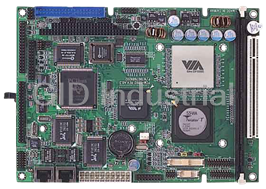
VIA C3 / Eden Low Power Processors
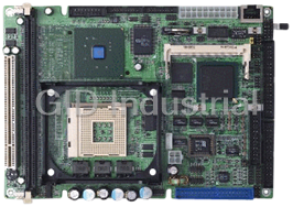
Compact Board with Intel Pentium 4/ Celeron Processors
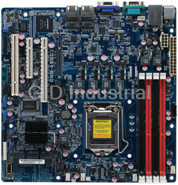
Entry Level Intel Xeon Server Board, UDIMM RAM/VGA/GbE x 2 LAN/2 USB
High Performance Server Board with Dual Intel Xeon Processors, RDIMM/UDIMM/LRDIMM RAM, VGA, 2 GbE LA...
Request a Quote

The quote request has been received
Close

Facing challenges or have inquiries? Feel free to contact us!
Call Us +1-469-283-2440
What they say about us
FANTASTIC RESOURCE
One of our top priorities is maintaining our business with precision, and we are constantly looking for affiliates that can help us achieve our goal. With the aid of GID Industrial, our obsolete product management has never been more efficient. They have been a great resource to our company, and have quickly become a go-to supplier on our list!
Bucher Emhart Glass
EXCELLENT SERVICE
With our strict fundamentals and high expectations, we were surprised when we came across GID Industrial and their competitive pricing. When we approached them with our issue, they were incredibly confident in being able to provide us with a seamless solution at the best price for us. GID Industrial quickly understood our needs and provided us with excellent service, as well as fully tested product to ensure what we received would be the right fit for our company.
Fuji
HARD TO FIND A BETTER PROVIDER
Our company provides services to aid in the manufacture of technological products, such as semiconductors and flat panel displays, and often searching for distributors of obsolete product we require can waste time and money. Finding GID Industrial proved to be a great asset to our company, with cost effective solutions and superior knowledge on all of their materials, it’d be hard to find a better provider of obsolete or hard to find products.
Applied Materials
CONSISTENTLY DELIVERS QUALITY SOLUTIONS
Over the years, the equipment used in our company becomes discontinued, but they’re still of great use to us and our customers. Once these products are no longer available through the manufacturer, finding a reliable, quick supplier is a necessity, and luckily for us, GID Industrial has provided the most trustworthy, quality solutions to our obsolete component needs.
Nidec Vamco
TERRIFIC RESOURCE
This company has been a terrific help to us (I work for Trican Well Service) in sourcing the Micron Ram Memory we needed for our Siemens computers. Great service! And great pricing! I know when the product is shipping and when it will arrive, all the way through the ordering process.
Trican Well Service
GO TO SOURCE
When I can't find an obsolete part, I first call GID and they'll come up with my parts every time. Great customer service and follow up as well. Scott emails me from time to time to touch base and see if we're having trouble finding something.....which is often with our 25 yr old equipment.
ConAgra Foods