

 Manufacturers
AAEON SBC-570N

Description
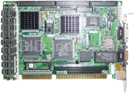
Full-size PCI/ISA Pentium CPU Card with Ultra-Wide SCSI Interface, Full-size PCI/ISA Pentium CPU Card
Part Number
SBC-570N
Price
Request Quote
Manufacturer
AAEON
Lead Time
Request Quote
Category
Single Board Computers
Specifications
Form Factor
PICMG 1.0
Datasheet

Extracted Text
SBC-570
Full-size PCI/ISA
Pentium CPU Card
with Ultra-Wide SCSI Interface
SBC-570N
Full-size PCI/ISA
Pentium CPU Card
FCC STATEMENT
THIS DEVICE COMPLIES WITH PART 15 FCC RULES.
OPERATION IS SUBJECT TO THE FOLLOWING TWO
CONDITIONS: (1) THIS DEVICE MAY NOT CAUSE
HARMFUL INTERFERENCE. (2) THIS DEVICE MUST
ACCEPT ANY INTERFERENCE RECEIVED INCLUDING
INTERFERENCE THAT MAY CAUSE UNDESIRED OPER-
ATION.
THIS EQUIPMENT HAS BEEN TESTED AND FOUND
TO COMPLY WITH THE LIMITS FOR A CLASS "A"
DIGITAL DEVICE, PURSUANT TO PART 15 OF THE
FCC RULES. THESE LIMITS ARE DESIGNED TO
PROVIDE REASONABLE PROTECTION AGAINTST
HARMFUL INTERFERENCE WHEN THE EQUIPMENT IS
OPERATED IN A COMMERCIAL ENVIRONMENT.
THIS EQUIPMENT GENERATES, USES, AND CAN
RADIATE RADIO FREQENCY ENERGY AND , IF NOT
INSTATLLED AND USED IN ACCORDANCE WITH THE
INSTRUCTION MANUAL, MAY CAUSE HARMFUL
INTERFERENCE TO RADIO COMMUNICATIONS.
OPERATION OF THIS EQUIPMENT IN A RESIDEN-
TIAL AREA IS LIKELY TO CAUSE HARMFUL INTER-
FERENCE IN WHICH CASE THE USER WILL BE
REQUIRED TO CORRECT THE INTERFERENCE AT HIS
OWN EXPENSE.
Acknowledgements
AMI is a trademark of American Megatrends, Inc.
Adaptec and AHA are trademarks of Adaptec, Inc.
AMD is a trademark of Advanced Micro Devices, Inc.
Award is a trademark of Award Software International, Inc
Cyrix is a trademark of Cyrix Corporation.
IBM, PC/AT, PS/2 and VGA are trademarks of International
Business Machines Corporation.
Intel and Pentium are trademarks of Intel Corporation.
®
Microsoft Windows is a registered trademark of Microsoft Corp.
SMC is a treademark of Standard Microsystems Corporation.
All other product names or trademarks are properties of their
respective owners.
Part No: 2007570020 SBC-570/570N 3rd Edition
Printed in Taiwan Nov 1997
Packing list
Before you begin installing your card, please make sure that the
following materials have been shipped:
• 1 SBC-570 CPU card/or SBC-570N CPU Card
• 1 Synchronous Cache Memory Module (160 Pin) - 256K
• 1 6-pin mini-DIN dual outlet adapter for keyboard and PS/2
mouse
• 1 Hard disk drive (IDE) interface cable (40 pin)
• 1 Floppy disk drive interface cable (34 pin)
• 1 Parallel port adapter (26 pin) and PS/2 adapter (4 pin) kit
• 1 Accessory for SBC series screw & support
• 1 SCSI cable (50 pin) (For SBC-570 only)
• 1 Ultra wide SCSI cable (68pin) (For SBC-570 only)
• Two SCSI Driver Disketts; One for Dos, Windows 3.1; One for
Novell-Netware V3.1x/V4.0/V4.1x , OS/2, WinNT 3.5X ,
WinNT4.0, Win95 (For SBC-570 only)
If any of these items are missing or damaged, contact your
distributor or sales representative immediately.
Contents
Chapter 1 General Information ..................................... 1
Introduction ............................................................................ 2
Features ................................................................................... 3
Specifications .......................................................................... 4
Board layout ........................................................................... 6
Card dimensions ..................................................................... 7
Chapter 2 Hardware Configuration ............................... 9
Jumpers and connectors ...................................................... 10
Locating jumpers and connectors ........................................ 11
Setting jumpers ..................................................................... 12
Safety precautions ................................................................ 13
Installing the CPU ................................................................ 14
Removing a CPU .................................................................... 14
Installing the CPU ................................................................... 14
CPU Speed Reference Table .................................................. 15
CPU Clock Slelect (JP6) ........................................................ 15
CPU Frequency Ratio Select (JP5) ......................................... 16
CPU Voltage Select (JP3) ....................................................... 16
CPU Core Voltage Select (JP4) .............................................. 17
CPU I/O Voltage Select (JP1) ................................................. 17
Flash BIOS Protect (JP7) ....................................................... 18
SCSI Terminator Select (JP2) ................................................. 18
Installing DRAM (SIMMs) .................................................. 19
Chapter 3 Connecting Peripherals .............................. 21
IrDA Tx/Rx Header (IR CON) ............................................. 24
Power LED and Keylock (KEYLOCK) .............................. 24
External Speaker (SPKER) .................................................. 25
Hard Drive LED (IDE LED) ................................................ 25
Reset Switch (RESET) .......................................................... 25
SCSI Device LED (SCSI LED) ............................................ 25
Enhanced IDE (PRIMARY IDE, SECONDARY IDE) ....... 26
Floppy Drive (FLOPPY DISK) ............................................ 26
Universal Serial Bus Connector (J1, J2) ............................. 27
Parallel Port (PRINTER) ..................................................... 27
Power Supply connections ................................................... 28
Power supply connector (POWER CON) .............................. 28
Serial Ports (COM-A, COM-B) ........................................... 28
Keyboard & PS/2 Mouse (KB/PS2 Mouse, KB CON, MS
COM) .................................................................................... 29
Ultra-Wide SCSI Connector (WIDE-SCSI CON) ............ 30
SCSI-II Connector (SCSI CON) ......................................... 31
Chapter 4 AMIBIOS Setup ......................................... 33
General information ............................................................. 34
Starting AMIBIOS setup ......................................................... 34
AMIBIOS main menu ............................................................. 34
Standard CMOS Setup ........................................................ 35
Advanced CMOS Setup ....................................................... 36
Advanced Chipset Setup ...................................................... 41
Power Management Setup ................................................... 43
PCI/Plug and Play Setup ..................................................... 46
Peripheral Setup ................................................................... 50
Auto-detect hard disk ........................................................... 53
Change Supervisor Password .............................................. 53
Auto Configuration with Optmal Settings ......................... 54
Auto Configuration with Fail Safe Settings........................ 54
Save Settings and Exit .......................................................... 54
Exit without Saving ............................................................... 54
Chapter 5 SCSI Driver Installation.......................... .. 55
Windows 95 Driver Installation....................................... 56
Windows NTv4.0 Driver Installation .................................. 58
Windows NT v3.5x Driver Installation ................................ 59
Netware V3.1x/V4.0/V4.1x Driver Installation ................... 61
OS/2 2.1x/Warp Driver Installation................................... 62
Windows 3.1x Driver Installation ........................................ 63
Dos Driver Installation ......................................................... 63
Appendix A: Programming the Watchdog Timer .... 65
Appendix B: Installing PC/104 Modules .................. 67
1
General
Information
This chapter gives background informa-
tion on the SBC-570.
Sections include:
• Card specifications
• Board layout
Chapter 1 General Information 1
CHAPTER
Introduction
The SBC-570 is an all-in-one single board Pentium computer with an
on-board high performance Ultra-wide SCSI interface. It packs all
the functions of an industrial computer on a single, full-size card. The
SBC-570 is fully PC/AT compatible; thus your software will run
without modifications. The Ultra-wide SCSI interface boosts
transfer rates to 40MB/sec and is capable of connecting 15 devices.
An 8-bit PCI SCSI_II interface is also available.
Other on-board features include a PCI Enhanced IDE interface, two
RS-232 ports with 16C550 UARTS, one bi-directional parallel port
and a flopppy drive controller. In addition to a 586 chip's 16 KB of
on-chip cache memory, the SBC-570 includes an extra 256 KB/ 512
KB of second level (L2) cache memory on-board.
The SBC-570's PCI Enhanced IDE interfaces supports (through ATA
PIO) mode 3 and mode 4 hard disks, which enables data transfer rates
in excess of 11 MB/sec. Up to four IDE devices can be connected,
including hard disks, CD-ROM drives, tape backup drives or other
IDE devices.
If program execution is halted by a program bug or EMI, the watch-
dog timer will automatically reset the CPU or generate an interrupt.
This ensures reliability in unmanned or standalone systems.
The SBC-570 supports BEDO, EDO DRAM or Fast page DRAM for
system memory. It provides four 72-pin SIMM (Single In-line
Memory Module) sockets in two banks to give you the flexibility to
configure your system from 8 MB to 128 MB of DRAM using the
most economical way.
2 SBC-570 User’s Manual
Features
• Accepts Intel Pentium CPU 75-200 MHz/P55C, AMD 5k86/K6,
Cyrix 6x86/M2, Socket 7 ZIF socket.
• Intel Triton VX chipset.
• Supports BEDO, EDO or Fast Page DRAM up to 128 MB.
• Supports Intel COAST cache module up to 512 KB to provide a high-
performance Level-2 cache subsystem.
• Built-in, Ultra wide SCSI interface with high speed 40MB/sec transfer
rates and capable of connecting 15 devices.
• Fast PCI enhanced IDE controller supports four IDE drives (large hard
disks, CD-ROM, tape backup, ect.).
• 32-bit PCI-bus, PICMG 2.0 standard.
• PnP I/O address & IRQ selection.
• Two high-speed serial RS-232 ports (16C550 UARTs with 16-byte FIFO).
• One enhanced bi-directional parallel port. Supports SPP/EPP/ECP.
• On-board keyboard and PS/2 Mouse connector, 16-bit PC/104 module
connector.
• Green functions.
Chapter 1 General Information 3
Specifications
• CPU: Intel Pentium CPU 75-200 MHz/
P55C, AMD 5k86/K6, Cyrix 6x86/M2
• Bus interface: PCI/ISA bus
• Bus speed: ISA: 8 MHZ
PCI: 25 ~ 33 MHz
• Data bus: 64 bit
• Processing ability: 64 bit
• PCI SCSI-II interface: 8-bit SCSI-II interface
• PCI Ultra-wide SCSI interface:16-bit Ultra-wide SCSI interface
(40MB/sec data transfer rate)
• PCI Enhanced IDE interface: Supports up to four IDE devices
including hard disk drives with PIO
mode 3, 4
• RAM memory: 8 MB to 128 MB. Uses two banks of
72-pin SIMM sockets, supports
BEDO, EDO, Fast page DRAM
• L2 Cache memory size: Supports up to 512 KB Intel COAST
module
• Shadow RAM memory: Supports system and video BIOS
shadow memory
• Floppy disk drive interface: Supports up to two floppy disk
drives, 5.25" (360 KB an 1.2 MB)
and/or 3.5" (720 KB, 1.44 and 2.88
MB)
• Parallel port: One bi-directional parallel port.
Supports SPP/EPP/ECP mode
• Serial ports: Two serial RS-232 ports; (IrDA Tx/
Rx header as an option). Both use
16C550 UARTs with 16-byte FIFO.
4 SBC-570 User’s Manual
• BIOS: AMI flash BIOS supports DMI, PnP,
Green features
Adaptec 7880 Ultra-wide SCSI RAID
BIOS (For SBC-570 only)
• Watchdog timer: The timeout interval is software select
able. (1 sec ~ 129 min 7 sec.)
• DMA channels: 7
• Interrupt levels: 15
• Keyboard / mouse connector: A 6-pin mini DIN connector supports
standard PC/AT keyboard and a PS/2
mouse.
• PC/104: 104-pin connector for a 16-bit bus
• USB: Supports 2 USB ports (reserved for
future use without testing).
• Power supply voltage: +5 V (4.75 V to 5.25 V), +12V power
supply
• Max. power requirements: +5 V @ 5 A
o o o
• Operating temperature: 32 F to 122 F (0 to 50 C)
• Board size: 13.3" (L) x 4.8" (W)
(338 mm x 122 mm)
• Board weight: 1.2 lbs (0.5 kg)
Chapter 1 General Information 5
ALTERA
EPM7032 adaptec
AIC7880P
32Mhz
SMC
FDC37C932
Board layout
6 SBC-570 User’s Manual
14.318
BIOS
40MHZ
SBC-570 PENTIUM WITH SCSI CPU CARD Rev.A1
intel intel
S82438V S82438V
intel
SB82437VX
Socket
intel
SB82371SB
RS-232 RS-232
Card dimensions
Chapter 1 General Information 7
SBC-590 Rev. A1 MADE IN TAIWAN R.O.C.
8 SBC-570 User’s Manual
2
Hardware
Configuration
This chapter gives background informa-
tion on the SBC-570. It explains how to
configure the card and prepare it for
installation into your PC.
Sections include:
• Jumper settings
• Safety precautions
• Installing DRAM (SIMMs)
Chapter 2 Hardware Configuration 9
CHAPTER
Jumpers and connectors
Connectors on the board link it to external devices such as hard
disk drives, a keyboard or floppy drives. In addition, the board has
a number of jumpers that allows you to configure your system to
suit your application. The table below lists the function of each of
the board jumpers and connectors.
Jumpers and connectors
Label Function
JP1 CPU I/O Voltage Select
JP2 SCSI Terminator Select
JP3 CPU Voltage Select
JP4 CPU Core Voltage Select
JP5 CPU Frequency Ratio Select
JP6 CPU Clock Select
JP7 Flash BIOS Protect
J1, J2 USB Connector
J4 PC/104 connector
CN12 Cache Socket
IR CON IrDA Tx/Rx header
KEYLOCK Keylock connector
SPKER Speaker connector
SCSI LED SCSI LED connector
IDE LED HDD LED connector
RESET RESET connector
PRIMARY IDE Primary IDE Connector
SECONDARY IDE Secondary IDE Connector
FLOPPY DISK Floppy drive Connector
PRINTER Printer Port
SCSI CON SCSI-II Connector
WIDE-SCSI CON Ultra-wide SCSI Connector
COM-A COM1
KB/PS2 MOUSE Keyboard and PS/2 mouse connector
MS CON Mouse connector
KB CON Keyboard connector
COM-B COM2
POWER CON Power connector (+5V, +12V, Gnd)
10 SBC-570 User’s Manual
ALTERA
EPM7032 adaptec
AIC7880P
32Mhz
SMC
FDC37C932
Locating jumpers and connectors
COM-A COM-B
POWER CON
KB/PS2 MOUSE
KB CON
MS CON
FLOPPY DISK
PRINTER
J 4
IR CON
JP7
PRIMARY IDE
SECONDARY IDE
J1, J2
JP2
WIDE-SCSI CON
SCSI CON
JP4 JP5
JP6
JP3
SCSI LED
IDE LED
SPKER
RESET
KEYLOCK
CN12
JP1
SIMM
Chapter 2 Hardware Configuration 11
14.318
BIOS
40MHZ
SBC-570 PENTIUM WITH SCSI CPU CARD Rev.A1
intel intel
S82438V S82438V
intel
SB82437VX
Socket
intel
SB82371SB
RS-232 RS-232
Setting jumpers
You configure your card to match the needs of your application by
setting jumpers. A jumper is the simplest kind of electric switch.
It consists of two metal pins and a small metal clip (often
protected by a plastic cover) that slides over the pins to connect
them. To “close” a jumper you connect the pins with the clip. To
“open” a jumper you remove the clip. Sometimes a jumper will
have three pins, labeled 1, 2 and 3. In this case you would connect
either pins 1 and 2 or 2 and 3.
3
2
1
Open Closed Closed 2-3
The jumper settings are schematically depicted in this manual as
follows:
1 2 3
Open Closed Closed 2-3
A pair of needle-nose pliers may be helpful when working with
jumpers.
If you have any doubts about the best hardware configuration for
your application, contact your local distributor or sales represen-
tative before you make any changes.
Generally, you simply need a standard cable to make most
connections.
12 SBC-570 User’s Manual
Safety precautions
Warning! Always completely disconnect the power cord
from your chassis whenever you are working on
it. Do not make connections while the power is
on, sensitive electronic components can be
damaged by the sudden rush of power. Only
experienced electronics personnel should open
the PC chassis.
Caution! Always ground yourself to remove any static
charge before touching the CPU card. Modern
electronic devices are very sensitive to static
electric charges. Use a grounding wrist strap at
all times. Place all electronic components on a
static-dissipative surface or in a static-shielded
bag when they are not in the chassis.
Chapter 2 Hardware Configuration 13
Installing the CPU
The SBC-570 CPU card supports Intel Pentium 75~200 and other
compatible CPUs at 66/60/55/50 MHz (external clock speed).
The system's performance depends on the CPU you choose. You
can install or upgrade the CPU in the board's ZIF socket by
following the procedures outlined below. If your system has an
existing CPU, you need to remove it before installing the new
CPU.
Removing a CPU
1. Pull the lever on the side of the ZIF socket out a little and
raise it up as far as it will go.
2. Lift the CPU out.
Installing the CPU
1. Make sure the ZIF socket lever is up as far as it can go. The
Pin 1 position is at the arm corner.
2. Match Pin 1 on the CPU with the Pin 1 position on the ZIF
socket. The pins on the three inner rings of the CPU should be
aligned with the holes on the ZIF socket.
3. Insert the CPU. If it does not go in easily, lift the lever higher.
4. Press the lever down. The sliding plate will move forward to
position the CPU. You will feel some resistance in the lever as
the CPU is secured into place. When the CPU is properly
installed, the lever will snap into place at the side of the ZIF
socket.
When you install a new CPU, you may have to adjust other
settings on the board, such as CPU type, CPU clock and PCI
speed, to accommodate it. Make sure that the settings are correct
for your CPU. Improper settings may damage the CPU.
14 SBC-570 User’s Manual
CPU Speed Reference Table
Refer to the CPU speed Reference Table (below) for instructions
on adjusting the internal clock according to the base CPU speed.
CPU speed Reference Table
CPU Speed (MHz) 75 90 100 120
Clock Setting 50 60 66 60
Frequency ratio 1.5 1.5 1.5 2
CPU Speed (MHz) 133 150 166 200
Clock Setting 66 60 66 66
Frequency ratio 2 2.5 2.5 3
CPU Clock Slelect (JP6)
JP6 set to select the CPU Clock.
CPU/PCI Clock Select (JP6)
JP6
CPU clock = 66 MHz* 1 2
3 4
1
CPU clock = 60 MHz 2
3
4
2
1
CPU clock = 55 MHz
4
3
CPU clock = 50 MHz
1 2
4
3
* default
Chapter 2 Hardware Configuration 15
CPU Frequency Ratio Select (JP5)
JP5 must be set to match the clock ratio of CPU. The chart
below shows the proper jumper setting.
CPU Frequency Ratio Select (JP5)
JP5
2
1
freq ratio = 3 4
3
6
5
1 2
freq ratio = 2.5* 3 4
5 6
1
2
3
freq ratio = 2
4
5
6
1
2
freq ratio = 1.5
3
4
5
6
* default
CPU Voltage Select (JP3)
CPU Voltage can be set by JP3 to reduce CPU Core Voltage
lower than CPU I/O Voltage or the same.
CPU Voltage Select (JP3)
2 4 6
Single Voltage*
1 3 5
2 4 6
Dual Voltage
1 3 5
* default
16 SBC-570 User’s Manual
CPU Core Voltage Select (JP4)
CPU Core Voltage can be set by JP4 to reduce power Consump-
tion and heat.
CPU Core Voltage Select (JP4)
JP4
1 2 3
CPU Core Voltage = 2.8V
1 2 3
CPU Core Voltage = 2.9V
1 2 3
CPU Core Voltage = 3.2V*
* default
CPU I/O Voltage Select (JP1)
JP1 must be set to match the CPU type. The chart below shows
the proper jumper setings for their respective CPU I/O Voltage:
CPU I/O Voltage Select (JP1)
JP1 JP4
1
1 2 3
CPU I/O Voltage = 3.3V 2
3
1
1 2 3
2
CPU I/O Voltage = 3.45 V*
3
1
1 2 3
2
CPU I/O Voltage = 3.52 V
3
* default
Chapter 2 Hardware Configuration 17
Flash BIOS Protect (JP7)
You can set the JP7 to protect BOIS and CMOS write-enable. The
Configuration is as follows
Flash BOIS Protect (JP7)
Write protect
1 2 3
Write enable*
1 2 3
* default
SCSI Terminator Select (JP2)
You can select the SCSI Terminator to ensure reliablity of the
SCSI bus communication enable or setting by SCSI BIOS. The
Configuration is as follows:
SCSI Terminator select (JP2)
Terminator enable*
1 2 3
Terminator select by SCSI BIOS
1 2 3
* default
18 SBC-570 User’s Manual
Installing DRAM (SIMMs)
The SBC-570 has four 72-pin SIMM (Single In-Line Memory
Module) sockets that provide anywhere from 1 MB to 128 MB of
DRAM. Each socket accepts from 1 to 32 MB of DRAM. For
more detailed information, refer to the memory configuration
table below.
Table 1: Dual or Quad SIMM (64-bit) boot-up
Bank O Bank 1
Total
Memory
SIMM 1 SIMM 2 SIMM 3 SIMM 4
2MB 1M 1M
4MB 2MB 2MB
4MB 1MB 1MB 1MB 1MB
8MB 4MB 4MB
8MB 2MB 2MB 2MB 2MB
16MB 8MB 8MB
16MB 4MB 4MB 4MB 4MB
32MB 16MB 16MB
32MB 8MB 8MB 8MB 8MB
64MB 16MB 16MB 16MB 16MB
64MB 32MB 32MB
128MB 32MB 32MB 32MB 32MB
24MB 4MB 4MB 8MB 8MB
48MB 8MB 8MB 16MB 16MB
96MB 16MB 16MB 32MB 32MB
40MB 4MB 4MB 16MB 16MB
80MB 8MB 8MB 32MB 32MB
Chapter 2 Hardware Configuration 19
20 SBC-570 User’s Manual
3
Connecting
Peripherals
This chapter describes how to connect
peripherals, switches and indicators to
the SBC-570 board. You can access most
of the connectors from the top of the
board while it is installed in the chassis.
If you have a number of cards installed,
or your chassis is very tight, you may
need to partially remove the card to make
all the connections.
Chapter 3 Connecting Peripherals 21
CHAPTER
The following table lists the connectors on the SBC-570. See
Chapter 1 to help locate the connectors.
SBC-570 Connector functions
Connector Function
J1, J2 USB connector
J4 PC/104 connector
IR CON IrDA Tx/Rx header
KEYLOCK Keylock connector
SPKER Speaker connector
SCSI LED SCSI LED connector
IDE LED HDD LED connector
RESET RESET connector
PRIMARY IDE Primary IDE connector
SECONDARY IDE Secondary IDE connector
FLOPPY DISK Floppy drive connector
PRINTER Printer port
SCSI CON SCSI-II connector
WIDE-SCSI CON Ultra-Wide SCSI connector
COM-A COM1
COM-B COM2
MS CON Mouse connector
KB CON Keyboard connector
KB/PS2 MOUSE Keyboard and PS/2 mouse connec-
tor
POWER CON Power Connector (+5V, +12V, Gnd)
The following sections describe how to make each connection. In
most cases, you need to connect a standard cable.
22 SBC-570 User’s Manual
Warning! Always completely disconnect the power cord
from your chassis whenever you are working on
it. Do not make connections while the power is
on. Sensitive electronic components can be
damaged by the sudden rush of power. Only
experienced electronics personnel should open
the PC chassis.
Caution! Always ground yourself to remove any static
charge before touching the CPU card. Modern
electronic devices are very sensitive to static
electric charges. Use a grounding wrist strap at
all times. Place all electronic components on a
static-dissipative surface or in a static-shielded
bag when they are not in the chassis.
Chapter 3 Connecting Peripherals 23
IrDA Tx/Rx Header (IR CON)
This connector supports the optional wireless transmitting and
receiving infrared module. This module mounts on a small
opening on system cases. You must also configure the setting
through BIOS setup to select whether UART2 is assigned for use
with COM2 or IrDA
IrDA Tx/Rx header (IR CON)
Pin Function
1 IrRx
2 GND
3 IrTx
4 Vcc
Power LED and Keylock (KEYLOCK)
You can use a LED to indicate the status that the CPU card is on.
Pin 1 of KEYLOCK provides the LED's power, and Pin 3 is the
ground.
You can use a switch (or a lock) to disable the keyboard so that
the PC will not respond to any input. This is useful if you do not
want anyone to change or stop a running program. Connect the
switch between Pins 4 and 5 of KEYLOCK.
Power LED and keylock
Pin Function
1 LED power (Vcc)
2NC
3 GND
4 Keyboard lock (IRQ1)
5 GND
24 SBC-570 User’s Manual
External Speaker (SPKER)
The CPU card has its own buzzer. You can also connect to the
external speaker on your computer chassis. Pin assignments for
SPKER are shown below:
External speaker (SPKER)
Pin Function
1 VCC
2 SPEAKER-
3 Internal Buzzer
4 SPEAKER-
Hard Drive LED (IDE LED)
You can connect a LED to the hard drive to indicate the status that
the HDD is active.
Reset Switch (RESET)
You can setup an external switch to easily reset your computer.
This switch restarts your computer as if you have turned off the
power, then turned it back on.
SCSI Device LED (SCSI LED)
You can connect an LED to indicate that a SCSI device is in use.
Chapter 3 Connecting Peripherals 25
Enhanced IDE (PRIMARY IDE,
SECONDARY IDE)
You can attach four IDE (Integrated Device Electronics) drives to
the SBC-570 's internal controller. The SBC-570 CPU card has
two EIDE connectors, PRIMARY IDE and SECONDARY IDE.
Wire number 1 on the cable is red or blue, the other wires are
gray. Connect one end to PRIMARY IDE or SECONDARY IDE
on the CPU card. Make sure that the red (or blue) wire corre-
sponds to pin 1 on the connector (on the right side).
Floppy Drive (FLOPPY DISK)
You can attach up to two floppy disk drives to the SBC-570's on-
board controller. You can use any combination of 5.25" (360 KB
and 1.2 MB) and 3.5" (720 KB, 1.44 MB and 2.88 MB) drives.
The card comes with a 34-pin daisy-chain drive connector cable.
On one end of the cable is a 34-pin flat-cable connector. On the
other end are two sets of floppy disk drive connectors. Each set
consists of a 34-pin flat-cable connector (usually used for 3.5"
drives) and a printed-circuit-board connector (usually used for
5.25" drives). You can use only one connector in each set. The set
on the end (after the twist in the cable) connects to the A drive.
The set in the middle connects to the B drive.
26 SBC-570 User’s Manual
Universal Serial Bus Connector (J1, J2)
The SBC-570 CPU card has two USB Connetors, their connec-
tion pin assignment is as follows.
USB Connector (J1, J2)
Pin Function
1 Vcc
2DATA -
3DATA +
4 GND
Parallel Port (PRINTER)
The parallel port is normally used to connect the CPU card to a
printer. The SBC-570 includes an on-board parallel port, accessed
through PRINTER, a 26-pin flat-cable connector. The card comes
with an adapter cable which lets you use a traditional DB-25
connector. The cable has a 26-pin connector on one end and a
DB-25 connector on the other, mounted on a retaining bracket.
The bracket can be installed at the end of an empty slot in your
chassis, allowing you to access the connector.
To install the bracket:
1. Find an empty slot in your chassis.
2. Unscrew the plate that covers the end of the slot, and screw in
the bracket.
3. Attach the flat-cable connector to PRINTER on the CPU card.
Wire 1 of the cable is red or blue, and the other wires are gray.
Make sure that wire 1 corresponds to pin 1 of PRINTER. Pin
1 is on the right side of PRINTER.
Chapter 3 Connecting Peripherals 27
Power Supply connections
Power supply connector (POWER CON)
In single-board computer (non-passive backplane) applications
you will need to connect power directly to the SBC-570 board
using the connector labeled POWER CON. This connector is
fully compatible with the standard PC power supply connector.
See the following table for its pin assignments:
Power Connector (POWER CON)
Pin Function
1 +12V
2 GND
3 GND
4 +5V
Serial Ports (COM-A, COM-B)
The SBC-570 offers two RS-232 serial ports, COM1 and COM2,
which let you connect to serial devices (a mouse, printers, etc.)
or a communication network. COM-A is
COM1, and COM-B is COM2.
DCD
1
DSR
6
RX
2
RTS
7
TX
3
You can disable each port or select its
CTS
8
DTR
address (3F8H [COM1], 2F8H [COM2] or
4
RI
9
3E8H) using the BIOS Advanced Setup GND
5
program.
Different devices implement the RS-232 standard in different
ways. If you get problems in a serial device, please check the pin
assignments of the connector. The above figure shows the pin
assignments of the card's RS-232 ports:
28 SBC-570 User’s Manual
Keyboard & PS/2 Mouse (KB/PS2
mouse, KB CON, MS COM)
KB/PS2 Mouse, the card's keyboard connector, is a 6-pin mini-
DIN connector on the card mounting bracket. The SBC-570 also
comes with an adapter to convert the mini-DIN connector to a
PC/AT keyboard connector and a PS/2 mouse connector.
KB/PS2 MOUSE
The SBC-570 provides a second connector designed for external
keyboard input (KB CON).
Keyboard Connector (KB CON)
Pin Function
1 KBCLK
2 KBDATA
3NC
4 KB GND
5 KB Vcc
Mouse Connector (MS CON)
Pin Function
1 MSCLK
2 MSDATA
3NC
4 KB GND
5 KB Vcc
Chapter 3 Connecting Peripherals 29
Ultra-Wide SCSI Connector (WIDE-SCSI
CON)
The Ultra-Wide SCSI Connector is a 68-pin, 16-bit SCSI Connec-
tor. If you are connecting internal SCSI devices, make sure you
have an internal SCSI cable with enough connectors to accommo-
date all of your devices.
1. Prepare each SCSI device for installation. Be sure to config-
ure the devices of SCSI ID and terminators (see the device's
documentation).
2. Install the SCSI device in your system
3. Plug one end of the internal SCSI cable into the host adapter's
internal SCSI Connector.
4. Plug the remaining SCSI cable connectors into the corre-
sponding connectors on the back of each individual device.
5. Connect the DC power cable into the SCSI's power connector.
The pin assignments are shown on the opposite page:
30 SBC-570 User’s Manual
Ultra-Wide SCSI Connector (WIDE-SCSI CON)
Pin Function Pin Function Pin Function Pin Function
1 GND 18 TPWR 35 -D12 52 TPWR
2 GND 19 NC 36 -D13 53 NC
3 GND 20 GND 37 -D14 54 GND
4 GND 21 GND 38 -D15 55 -ATTN
5 GND 22 GND 39 -DPH 56 GND
6 GND 23 GND 40 -DO 57 -BSY
7 GND 24 GND 41 -D1 58 -ACK
8 GND 25 GND 42 -D2 59 -RST
9 GND 26 GND 43 -D3 60 -MSG
10 GND 27 GND 44 -D4 61 -SEL
11 GND 28 GND 45 -D5 62 -CD
12 GND 29 GND 46 -D6 63 -REQ
13 GND 30 GND 47 -D7 64 -IO
14 GND 31 GND 48 -DPL 65 -D8
15 GND 32 GND 49 GND 66 -D9
16 GND 33 GND 50 GND 67 -D10
17 TPWR 34 GND 51 TPWR 68 -D11
SCSI-II Connector (SCSI CON)
The SCSI CON is a 50-pin, 8-bit SCSI connector available for
internal SCSI device use. Connection of SCSI devices requires
special attention, especially when determining the last drive in the
SCSI chain. Refer to your device's operating manual for detailed
installation advice. The pin assignments are shown on the
following page.
Chapter 3 Connecting Peripherals 31
SCSI-II Connector (SCSI CON)
Pin Function Pin Function
1 GND 2 -D0
3 GND 4 -D1
5 GND 6 -D2
7 GND 8 -D3
9 GND 10 -D4
11 GND 12 -D5
13 GND 14 -D6
15 GND 16 -D7
17 GND 18 -DPL
19 GND 20 GND
21 GND 22 GND
23 GND 24 GND
25 NC 26 TRMPWR
27 GND 28 GND
29 GND 30 GND
31 GND 32 -ATTN
33 GND 34 GND
35 GND 36 -BSY
37 GND 38 -ACK
39 GND 40 -RST
41 GND 42 -MSG
43 GND 44 -SEL
45 GND 46 -CD
47 GND 48 -REQ
49 GND 50 -IO
32 SBC-570 User’s Manual
4
AMIBIOS Setup
This chapter describes how to set BIOS
configuration data.
CHAPTER
General information
AMIBIOS Setup configures system information that is stored in
CMOS RAM.
Starting AMIBIOS setup
As POST executes, the following appears;
Hit if you want to run SETUP
Press to run AMIBIOS setup.
AMIBIOS main menu
The AMIBIOS setup screen appears as follows:
AMIBIOS HIFLEX SETUP UTILITY — VERSION 1.07
(C) 1996 American Megatrends, Inc. All Rights Reserved
Standard CMOS Setup
Advanced CMOS Setup
Advanced Chipset Setup
Power Management Setup
PCI/ Plug and Play Setup
Peripheral Setup
Auto-Detect Hard Disks
Change User Password
Change Supervisor Password
Change Language Setting
Auto-configuration with Optimal Settings
Auto Configuration with Fail Safe Settings
Save Settings and Exit
Exit Without Saving
Standard CMOS setup for changing time, date, hard disk type, etc.
34 SBC-570 User’s Manual
Standard CMOS Setup
The AMIBIOS Setup options described in this section are
selected by choosing the Standard CMOS Setup from the
AMIBIOS Setup main menu selection screen, as shown below.
The Standard CMOS Setup screen appears:
AMIBIOS SETUP — STANDARD CMOS SETUP
(C) 1996 American Megatrends, Inc. All Rights Reserved
Date (mm/dd/yyyy): Wed Aug 21, 1996
Time (hh/mm/ss): 12: 19: 46
Floppy Drive A: 1.44 MB 3½
Floppy Drive B: Not Installed
LBA Blk PIO 32Bit
Type Size Cyln Head WPcom Sec Mode Mode Mode Mode
Pri Master: Auto
Pri Slave Auto
Sec Master Auto
Sec Slave Auto
Boot Sector Virus Protection Disabled
Month: Jan - Dec Esc: Exit ¯- :Sel
Day: 01-31 PgUp/PgDn: Modify
Year: 1901 -2099 F2/F3: Color
Date, Day and Time Configuration
The current values for each category are displayed. Enter new
values through the keyboard.
Floppy A, Floppy B
Select the appropriate specifications to configure the type of
floppy drive that is attached to the system: 360 KB 5¼", 1.2 MB
5¼", 720 KB 3½", 1.44 MB 3½", and/or 2.88 MB 3½". The
settings have not been pre-installed.
Chapter 4 AMIBIOS Setup 35
Master Disk, Slave Disk
Select the appropriate values to configure the hard disk type you
are using for the master and the slave. The settings have not been
pre-installed. Available types are 1~46, User, Auto, Not Installed
and CDROM.
Boot Sector Virus Protection
Enabling this option allows the system to issue a warning when
any program (or virus) issues a disk format command or attempts
to write to the boot sector of the hard disk drive. Further confir-
mation is required before accessing this particular section of the
hard disk drive.
Advanced CMOS Setup
Select the Advanced CMOS Setup from the AMIBIOS Setup main
menu to enter Advanced setup.
The Advanced Setup options described in this section are the
standard options as shown on the following screen. The following
configurations are based on Fail-Safe default settings.
AMIBIOS SETUP — ADVANCED CMOS SETUP
(C) 1996 American Megatrends, Inc. All Rights Reserved
Quick Boot Disabled
Available Options:
BootUp Sequence A:, C:, CDROM
Disabled
BootUp Num-Lock On
Enabled
Floppy Drive Swap Disabled
Floppy Drive Seek Disabled
PS/2 Mouse Support Enabled
System Keyboard Present
Primary Display VGA/EGA
Password Check Setup
Parity Check Disabled
OS/2 Compatible Mode Disabled
Wait For 'F1' If Error Enabled
Hit 'DEL' Message Display Enabled
Internal Cache WriteBack
External Cache Disabled
System BIOS Cacheable Disabled
C000, 32k Shadow Enabled
C800, 16k Shadow Disabled
CC00, 16k Shadow Disabled
D000, 16k Shadow Disabled
D400, 16k Shadow Disabled
ESC: Exit :Sel ¯-
D800, 16k Shadow Disabled
PgUp/PgDn: Modify
DC00, 16k Shadow Disabled
F2/F3: Color
36 SBC-570 User’s Manual
Quick Boot:
Set this option to Enabled to instruct AMIBIOS to boot quickly
when the computer is powered on. This option replaces the old
Above 1 MB Memory Test Advanced Setup option.
Setting Description
Disabled AMIBIOS test all system memory. AMIBIOS waits up
to 40 seconds for a READY signal from the IDE hard
disk drive. AMIBIOS waits for .5 seconds after sending
a RESET signal to the IDE drive to allow the IDE drive
time to get ready again. AMIBIOS checks for a
key press and runs AMIBIOS Setup if the key has
been pressed.
Enabled AMIBIOS does not test system memory above 1 MB.
AMIBIOS does not wait up to 40 seconds for a
READY signal from the IDE hard disk drive. If a
READY signal is not received immediately from the
IDE drive, AMIBIOS does not configure that drive.
AMIBIOS does not wait for .5 seconds after sending a
RESET signal to the IDE drive to allow the IDE drive
time to get ready again.
You cannot run AMIBIOS Setup at system boot,
because there is no delay for the Hit to run
Setup message.
Boot Up Sequence:
This option sets the sequence of boot drives (floppy drive A:, hard
disk drive C:, or CD-ROM drive) that the AMIBIOS attempts to
boot from after AMIBIOS POST completes.
Boot Up Num Lock:
Set this option to Off to turn the Num Lock key off when the
computer is booted so you can use the arrow keys on both the
numeric keypad and the keyboard. The settings are On or Off.
Chapter 4 AMIBIOS Setup 37
Floppy Drive Swap:
Set this option to Enabled to permit drives A: or B: to be
swapped. The settings are Enabled or Disabled.
Floppy Drive Seek:
Set this option to Enabled to specify that floppy drive A: will
perform a Seek operation at system boot. The settings are
Enabled or Disabled.
PS/2 Mouse Support:
When this option is set to Enabled, AMIBIOS supports a PS/2-
type mouse. The settings are Enabled or Disabled.
System Keyboard:
This option specifies that a keyboard is attached to the computer.
The settings are Present or Absent.
Primary Display:
This option specifies the type of display monitor and adapter
in the computer. The settings are Mono, CGA40x25, CGA80x25,
VGA/EGA, or Absent.
Password Check:
This option enables password checking every time the computer
is powered on or every time AMIBIOS Setup is executed. If
Always is chosen, a user password prompt appears every time the
computer is turned on. If Setup is chosen, the password prompt
appears as AMIBIOS is executed.
Parity Check:
Set this option to Enabled to check the parity of all system
memory. The settings are Enabled or Disabled.
38 SBC-570 User’s Manual
OS/2 Compatible Mode:
Set this option to Enabled to permit AMIBIOS to run with IBM
OS/2. The settings are Enabled or Disabled.
Wait for ’F1’ if Error:
AMIBIOS POST error messages are followed by:
Press if you want to run Setup
from appearing on the first AMIBIOS screen when the computer
boots. The settings are Enabled or Disabled.
Internal Cache:
This option specifies the caching algorithm used for L1 internal
cache memory. The setting are:
Setting Description
Disabled Neither L1 internal cache memory on the
CPU nor L2 secondary cache memory is
enabled.
WriteBack Use the write-back caching algorithm.
External Cache
Set this option to Enabled the L2 secondary cache.
System BIOS Cacheable
When this option is set to Enabled, the contents of the F0000h
system memory segment can be read from or written to L2
secondary cache memory. The contents of the F0000h memory
segment are always copied from the BIOS ROM to system RAM
for faster execution.
The settings are Enabled or Disabled.
Chapter 4 AMIBIOS Setup 39
C000,32k Shadow D000,16k Shadow
C800,16k Shadow D400,16k Shadow
CC00,16k Shadow D800,16k Shadow
DC00,16k Shadow
These options control the location of the contents of the 16KB of
ROM beginning at the specified memory location. If no adapter
ROM is using the named ROM area, this area is made available to
the local bus. The settings are:
Setting Description
Enabled The contents of C0000h - C3FFFh are written to the
same address in system memory (RAM) for faster
execution.
Cached The contents of the named ROM area are written to
the same address in system memory (RAM) for faster
execution, if an adapter ROM will be using the named
ROM area. Also, the contents of the RAM area can be
read from and written to cache memory.
Disabled The video ROM is not copied to RAM. The contents of
the video ROM cannot be read from or written to cache
memory.
40 SBC-570 User’s Manual
Advanced Chipset Setup
Select the Advanced Chipset Setup from the AMIBIOS Setup
main menu to enter the Chipset Setup. The following configura-
tions are based on Fail-Safe default settings.
AMIBIOS SETUP — ADVANCED CHIPSET SETUP
(C) 1996 American Megatrends, Inc. All Rights Reserved
Memory Hole Disabled Available Options:
DRAM Timing Setting Auto Disabled
Fast MA to RAS# Delay 1 clock 512K-640K
EDO: SPM Read Burst Timing x333:x444 15M-16M
DRAM Write Burst Timing x333
Fast RAS to CAS Delay 3 Clocks
DRAM Leadoff Timing 10-6-4
Refresh RAS# Assertion 5 Clocks
Fast EDO Path Select Disabled
SDRAM CAS# Latency 3
SDRAM RAS# Timing 3:5:8
8Bit I/O Recovery Time (Sysclk) 1
16Bit I/O Recovery Time (Sysclk) 1
PCI 2.1 Passive Release Enable Enabled
Delayed Transaction Enable Enabled
USB Function Enable Disabled
ESC: Exit :Sel ¯-
USB KeyBoard Support Disabled
USB Passive Release Enable Disabled PgUp/PgDn: Modify
USB Clock 48 Mhz F2/F3: Color
Memory Hole
This option allows the end user to specify the location of a
memory hole. The settings are Disabled, 512K-640K, or 15M-
16M (from 15 MB to 16 MB).
DRAM Timing Setting
Set this option to Auto to make the BIOS auto defect the DRAM
timing setting. Select Manual to manually choose the the DRAM
timing setting.
Chapter 4 AMIBIOS Setup 41
8Bit I/O Recovery Time
This option specifies the length of a delay inserted between
consecutive 8-bit I/O operations. The settings are Disabled, 1
(SYSCLK), 2 (SYSCLKs), 3 (SYSCLKs), 4 (SYSCLKs), 5 (SY-
SCLKs), 6 (SYSCLKs), or 8 (SYSCLKs).
16Bit I/O Recovery Time
This option specifies the length of a delay inserted between
consecutive 16-bit I/O operations. The settings are Disabled,
1(SYSCLK), 2 (SYSCLKs), 3 (SYSCLKs), or 4 (SYSCLKs).
PCI 2.1 Passive Release Enable
Set this option to Enabled to enable the PCI passive release
feature defined in Version 2.1 of the PCI specification. The
settings are Enabled or Disabled.
Delayed Transaction Enable
Set this option to Enabled to enable the delayed transaction
feature. The settings are Enabled or Disabled.
USB Funtion Enable
Set this option Enabled to enable the system BIOS USB (Univer-
sal Serial Bus) functions. The settings are Enabled or Disabled.
USB KeyBoard Support
Set this option to Enabled to enable keyboard support on the
universal serial bus.
USB Passive Release Enable
Set this option to Enabled to enable passive release on the
universal serial bus. The settings are Enabled or Disabled.
USB Clock
This option sets the clock for the Universal Serial Bus. The
settings are 24 Mhz or 48 Mhz.
42 SBC-570 User’s Manual
Power Management Setup
The POWER MANAGEMENT SETUP allows you to configure
your system for the most effective use of energy while operating
in a manner consistant with your own style of computer use. The
following configurations are based on Fail-Safe default settings.
AMIBIOS SETUP — POWER MANAGEMENT SETUP
(C) 1996 American Megatrends, Inc. All Rights Reserved
Power Management/APM Disabled Available Options:
Instant-On Timeout (Minute) Disabled Disabled
Green PC Monitor Power State Standby Enabled
Monitor Power down mode VESA
Video Power Down Mode Disabled
Hard Disk Power Down Mode Disabled
Hard Disk Time Out (Minute) Disabled
Standby Time Out (Minute) Disabled
Suspend Time Out (Minute) Disabled
Slow Clock Ratio 1:8
Display Activity Ignore
IRQ3 lgnore
IRQ4 lgnore
IRQ5 Ignore
IRQ7 Ignore
IRQ9 Ignore
IRQ10 Ignore
IRQ11 Ignore
IRQ12 lgnore
IRQ13 Ignore ESC: Exit :Sel ¯-
IRQ14 lgnore Pg Up/Pg Dn: Modify
IRQ15 lgnore F2/F3: Color
Power Management/APM
Set this option to Enabled to enable the power management and
APM (Advanced Power Management) features. The settings are
Inst-ON, Enabled or Disabled.
Green PC Monitor Power State
This option specifies the power state that the green PC-compliant
video monitor enters when AMIBIOS places it in a power savings
state after the specified period of display inactivity has expired.
The settings are Off, Standby, or Suspend.
Monitor Power down mode
The settings of Monitor Power down mode are VESA or Blank
off.
Chapter 4 AMIBIOS Setup 43
Video Power Down Mode
This option specifies the power conserving state that the VESA
VGA video subsystem enters after the specified period of display
inactivity has expired. The settings are Disabled, Standby, or
Suspend.
Hard Disk Power Down Mode
This option specifies the power conserving state that the hard disk
drive enters after the specified period of hard drive inactivity has
expired. The settings are Disabled, Standby, or Suspend.
Hard Disk Time Out (Minute)
This option specifies the length of a period of hard disk drive
inactivity. When this length of time expires, the computer enters
power-conserving state specified in the Hard Disk Power Down
Mode option. The settings are Disabled, 1 (min), 2 (min), 3
(min), 4 (min), 5 (min), 6 (min), 7 (min), 8 (min), 9 (min), 10 (min),
11 (min), 12 (min), 13 (min), or 14 (min).
Standby Timeout (Minute)
This option specifies the length of a period of system inactivity
while in Full power on state. When this length of time expires,
the computer enters Standby power state. The steeings are
Disabled, 1 (min), 2 (min), 3 (min), 4 (min), 5 (min), 6 (min), 7
(min), 8 (min), 9 (min), 10 (min), 11 (min), 12 (min), 13 (min), or
14 (min).
Suspend timeout (Minute)
This option specifies the length of a period of system inactivity
while in Standby state. When this length of time expires, the
computer enters Suspend power state. The settings are Disabled,
1 (min), 2 (min), 3 (min), 4 (min), 5 (min), 6 (min), 7 (min), 8
(min), 9 (min), 10 (min), 11 (min), 12 (min), 13 (min), or 14 (min).
Slow Clock Ratio
This option specifies the speed at which the system clock runs in
power saving states. The settings are expressed as a ratio between
the normal CPU clock speed and the CPU clock speed when the
computer is in the power-conserving state. The settings are 1:1,
1:2, 1:4, 1:8, 1:16, 1:32, 1:64, or 1:128.
44 SBC-570 User’s Manual
Display Activity
This option specifies if AMIBIOS is to monitor display activity
for power conservation purposes. When this option is set to
Monitor and there is no display activity for the length of time
specified in the Standby Timeout (Minute) option, the comput-
er enters a power savings state. The settings are Monitor or
Ignore.
IRQ3
IRQ4
IRQ5
IRQ7
IRQ9
IRQ10
IRQ11
IRQ12
IRQ13
IRQ14
IRQ15
When set to Monitor, these options enable event monitoring on
the specified hardware interrupt request line. If set to Monitor
and the computer is in a power saving state, AMIBIOS watches for
activity on the specified IRQ line. The computer enters the full
on power state if any activity occurs.
AMIBIOS reloads the Standby and Suspend timeout timers if
activity occurs on the specified IRQ line.
The settings for each of these options are Monitor or Ignore.
Chapter 4 AMIBIOS Setup 45
PCI/Plug and Play Setup
This section describes configuring the PCI bus system and covers
some very technical items. It is STRONGLY RECOMMENDED
that only experienced users should make any changes to the
default settings.
.AMIBIOS SETUP — PCI / PLUG AND PLAY SETUP
(C) 1996 American Megatrends, Inc. All Rights Reserved
ON BOARD SCSI Enabled Available Options:
Reset NVRAM No Disabled
Plug and Play Aware O/S No 16K
PCI IRQ Priority Auto Setting Yes 32K
1st Available IRQ IRQ 11 64K
2nd Available IRQ IRQ 10
3rd Available IRQ IRQ 9
4th Available IRQ IRQ 12
PCI Latency Timer (PCI Clocks) 32
Assign IRQ to PCI VGA Card No
PCI IDE BusMaster Disabled
OffBoard PCI IDE Card Auto
OffBoard PCI IDE Primary IRQ Disabled
OffBoard PCI IDE Secondary IRQ Disabled
DMA Channel 0 PnP
DMA Channel 1 PnP
DMA Channel 3 PnP
DMA Channel 5 PnP
DMA Channel 6 PnP
DMA Channel 7 PnP
IRQ3 PCI/PnP
IRQ4 PCI/PnP
IRQ5 PCI/PnP
IRQ7 PCI/PnP
IRQ9 PCI/PnP
IRQ10 PCI/PnP
IRQ11 PCI/PnP
IRQ14 PCI/PnP ESC: Exit :Sel ¯-
lRQ15 PCI/PnP Pg Up/Pg Dn: Modify
Reserved Memory Size Disabled F2/F3: Color
Reserved Memory Address C8000
ON BOARD SCSI
Set this option to Enabled to allow SCSI device be detected by
the BIOS. The settings are Enabled or Disabled.
Reset NVRAM
Set this option to Yes to reset NVRAM. The settings are Yes or
No.
46 SBC-570 User’s Manual
Plug and Play Aware OS
Set this option to Yes if the operating system installed in the
computer is Plug and Play-aware. AMIBIOS only detects and
enables PnP ISA adapter cards that are required for system boot.
The Windows 95 operating system detects and enables all other
PnP-aware adapter cards. Windows 95 is PnP-aware. Set this
option to No if the operating system (such as DOS, OS/2,
Windows 3.x) does not use PnP.
You must set this option correctly or PnP-aware adapter cards
installed in your computer will not be configured properly.
The settings are No or Yes.
PCI IRQ Priority Auto Setting
Set this option to Yes to auto set PCI IRQ Priority by the BIOS.
The settings are Yes or No.
1st Available IRQ
2nd Available IRQ
3rd Available IRQ
4th Available IRQ
If PCI IRQ Priority Auto Setting is set to No, you can manually
select 1st available or 2nd available IRQ. The settings are IRQ 3,
IRQ 4, IRQ 5, IRQ 7, IRQ 9, IRQ 10, IRQ 11, IRQ 12.
PCI Latency Timer (PCI Clocks)
This option sets latency of all PCI devices on the PCI bus. The
settings are in units equal to PCI clocks. The settings are 32, 64,
96, 128, 160, 192, 224, or 248.
Assign IRQ to PCI VGA Card
Set this option to Yes to assign IRQ to PCI VGA Card. The
settings are Yes or No.
PCI IDE BusMaster
Set this option to Enabled to specify that the IDE controller on
the PCI local bus has bus mastering capability. The settings are
Disabled or Enabled.
Chapter 4 AMIBIOS Setup 47
OffBoard PCI IDE Card
This option specifies if an offboard PCI IDE controller adapter
card is used in the computer. You must also specify the PCI
expansion slot on the motherboard where the offboard PCI IDE
controller card is installed. If an offboard PCI IDE controller is
used, the onboard IDE controller on the motherboard is automati-
cally disabled. The settings are Auto, Slot1, Slot2, Slot3, or
Slot4.
If Auto is selected, AMIBIOS automatically determines the
correct setting for this option.
OffBoard PCI IDE Primary IRQ
This option specifies the PCI interrupt used by the primary IDE
channel on the offboard PCI IDE controller. The settings are
Disabled, INTA, INTB, INTC, INTD, or Hardwired.
OffBoard PCI IDE Secondary IRQ
This option specifies the PCI interrupt used by the secondary IDE
channel on the offboard PCI IDE controller. The settings are
Disabled, INTA, INTB, INTC, INTD, or Hardwired.
DMA Channel 0
DMA Channel 1
DMA Channel 3
DMA Channel 5
DMA Channel 6
DMA Channel 7
This item allows you to defermine the specified DMA Channel
assigned to the ISA/EISA bus, or configured as Plug and Play
(PnP).
48 SBC-570 User’s Manual
IRQ3
IRQ4
IRQ5
IRQ7
IRQ9
IRQ10
IRQ11
IRQ14
IRQ15
These options specify the bus that the named interrupt request
lines (IRQs) are used on. These options allow you to specify
IRQs for use by legacy ISA adapter cards.
These options determine if AMIBIOS should remove an IRQ from
the pool of available IRQs passed to BIOS configurable devices.
The available IRQ pool is determined by reading the ESCD
NVRAM. If more IRQs must be removed from the pool, the end
user can use these PCI/PnP Setup options to remove the IRQ by
assigning the option to the ISA/EISA setting. Onboard I/O is
configurable by AMIBIOS. The IRQs used by onboard I/O are
configured as PCI/PnP.
The settings are PCI/PnP or ISA/EISA.
Reserved Memory Size
This option specifies the size of the memory area reserved for
legacy ISA adapter cards.
The settings are Disabled, 16k, 32k, or 64k.
Reserved Memory Address
This option specifies the beginning address (in hex) of the
reserved memory area. The specified ROM memory area is
reserved for use by legacy ISA adapter cards.
The settings are C0000, C4000, C8000, CC000, D0000, D4000,
D8000, or DC000.
Chapter 4 AMIBIOS Setup 49
Peripheral Setup
To access Periperal Setup, select the Periperal icon in the
AMIBIOS main menu. The following screen appears
.
AMIBIOS SETUP — PERIPHERAL SETUP
(C) 1996 American Megatrends, Inc. All Rights Reserved
OnBoard FDC Auto Available Options
OnBoard Serial Port 1 Auto Auto
OnBoard Serial Port 2 Auto Disabled
Serial Port 2 Receive Polarity High Enabled
Serial Port 2 Transmit Polarity High
Serial Port 2 IR Mode Disabled
Serial Port 2 Duplex Full
OnBoard Parallel Port Auto
Parallel Port IRQ Auto
Parallel Port Mode Normal
Parallel Port DMA Channel None
OnBoard IDE Both
ESC: Exit :Sel
¯-
Pg Up/Pg Dn: Modify
F2/F3: Color
OnBoard FDC
This option enables the floppy drive controller on the mother-
board. The settings are Auto, Enabled or Disabled.
OnBoard Serial Port 1
This option enables serial port 1 on the motherboard and
specifies the base I/O port address for serial port 1.
The settings are Auto, Disabled, 3F8h, 3E8h, 2E8h,2F8h.
OnBoard Serial Port2
This option enables serial port 2 on the motherboard and speci-
fies the base I/O port address for serial port 2. The settings are
Auto. Disabled, 3F8h, 2F8h, 3E8h, 2E8h.
Serial Port2 Receive Polarity
The settings of this option are High or Low.
Serial Port2 Transmit Polarity
The settings of this option are High or Low.
50 SBC-570 User’s Manual
Serial Port2 IR Mode
The settings of this option are Disabled, IrDA or ASK-IR.
Serial Port2 Duplex
Set this option to Full Duplex or Half Duplex.
OnBoard Parallel Port
This option enables the parallel port on the motherboard and
specifies the parallel port base I/O port address. The settings are
Auto, Disabled, 378h, 278h, 3BCh.
Parallel Port IRQ
IRQ7 is used for the Parallel Port(LPT 1). The IRQ can be
changed to IRQ5.
Parallel Port Mode
This option specifies the parallel port mode. ECP and EPP are
both bidirectional data transfer sechemes that adhere to the IEEE
P1284 specification. The settings are:
Setting Description
Normal The normal parallel port mode is used. This is the
default setting.
Bi-Dir Use this setting to support bidirectional transfers on
the parallel port.
EPP The parallel port can be used with devices that adhere
to the Enhanced Parallel Port (EPP) specification.
EPP uses the exiting parallel port signals to provide
asymmetric bidirectional data transfer driven by the
host device.
ECP The parallel port can be used with devices that adhere
to the Extended Capabilities Port (ECP) specification.
ECP uses the DMA protocol to achieve transfer rates
of approximately 2.5 Mbs. ECP provides symmetric
bidirectional communlations.
Parallel Port DMA Channel
This option is only available if the setting for the Parallel Port
Mode option is ECP.
The settings are Auto, None, 0, 1, 2, 3.
Chapter 4 AMIBIOS Setup 51
Onboard IDE
This option specifies the onboard IDE controller channels that
will be used. The settings are Primary, Secondary, Both, or
Disabled.
52 SBC-570 User’s Manual
Auto-detect hard disk
The "IDE HDD AUTO DETECTION" utility can automatically
detect the IDE hard disk installed in your system. You can use it
to self-detect and/or correct the hard disk type configuration.
AMIBIOS SETUP — STANDARD CMOS SETUP
(C) 1996 American Megatrends, Inc. All Rights Reserved
Date (mm/dd/yyyy): Wed Aug 21, 1996
Time (hh/mm/ss): 12: 19: 46
Floppy Drive A: 1.44 MB 3½
Floppy Drive B: Not Installed
LBA BLK PIO 32-bit
Type Size Cyln Head WPcom Sec Mode Mode Mode Mode
Pri Master: Auto 41 1050 2 65535 40 OFF ON 0 ON
Pri Slave Auto
Sec Master Auto
Sec Slave Auto
Boot Sector Virus Protection Disabled
Month: Jan - Dec Esc: Exit ¯- :Sel
Day: 01-31 PgUp/PgDn: Modify
Year: 1901 -2099 F2/F3: Color
Change Supervisor Password
1) Select this option from the main menu
2) Enter the Password and Press
Frequently asked questions
How does Industrial Trading differ from its competitors?

Is there a warranty for the SBC-570N?
Which carrier will Industrial Trading use to ship my parts?
Can I buy parts from Industrial Trading if I am outside the USA?
Which payment methods does Industrial Trading accept?
Why buy from GID?

Quality
We are industry veterans who take pride in our work

Protection
Avoid the dangers of risky trading in the gray market

Access
Our network of suppliers is ready and at your disposal

Savings
Maintain legacy systems to prevent costly downtime

Speed
Time is of the essence, and we are respectful of yours
Related Products
486DX5-133 Half-size CPU Card with LCD, Ethernet, & SSD
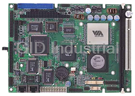
VIA C3 / Eden Low Power Processors
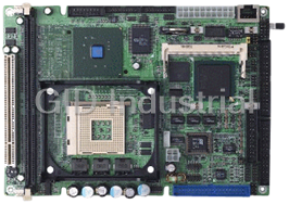
Compact Board with Intel Pentium 4/ Celeron Processors
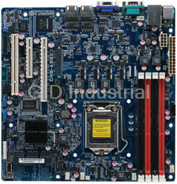
Entry Level Intel Xeon Server Board, UDIMM RAM/VGA/GbE x 2 LAN/2 USB
High Performance Server Board with Dual Intel Xeon Processors, RDIMM/UDIMM/LRDIMM RAM, VGA, 2 GbE LA...
Request a Quote

The quote request has been received
Close

Facing challenges or have inquiries? Feel free to contact us!
Call Us +1-469-283-2440
What they say about us
FANTASTIC RESOURCE
One of our top priorities is maintaining our business with precision, and we are constantly looking for affiliates that can help us achieve our goal. With the aid of GID Industrial, our obsolete product management has never been more efficient. They have been a great resource to our company, and have quickly become a go-to supplier on our list!
Bucher Emhart Glass
EXCELLENT SERVICE
With our strict fundamentals and high expectations, we were surprised when we came across GID Industrial and their competitive pricing. When we approached them with our issue, they were incredibly confident in being able to provide us with a seamless solution at the best price for us. GID Industrial quickly understood our needs and provided us with excellent service, as well as fully tested product to ensure what we received would be the right fit for our company.
Fuji
HARD TO FIND A BETTER PROVIDER
Our company provides services to aid in the manufacture of technological products, such as semiconductors and flat panel displays, and often searching for distributors of obsolete product we require can waste time and money. Finding GID Industrial proved to be a great asset to our company, with cost effective solutions and superior knowledge on all of their materials, it’d be hard to find a better provider of obsolete or hard to find products.
Applied Materials
CONSISTENTLY DELIVERS QUALITY SOLUTIONS
Over the years, the equipment used in our company becomes discontinued, but they’re still of great use to us and our customers. Once these products are no longer available through the manufacturer, finding a reliable, quick supplier is a necessity, and luckily for us, GID Industrial has provided the most trustworthy, quality solutions to our obsolete component needs.
Nidec Vamco
TERRIFIC RESOURCE
This company has been a terrific help to us (I work for Trican Well Service) in sourcing the Micron Ram Memory we needed for our Siemens computers. Great service! And great pricing! I know when the product is shipping and when it will arrive, all the way through the ordering process.
Trican Well Service
GO TO SOURCE
When I can't find an obsolete part, I first call GID and they'll come up with my parts every time. Great customer service and follow up as well. Scott emails me from time to time to touch base and see if we're having trouble finding something.....which is often with our 25 yr old equipment.
ConAgra Foods