

 Manufacturers
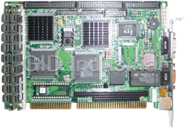
AAEON SBC-554

Description
Half-size 586 CPU Card with PISA Bus
Part Number
SBC-554
Price
Request Quote
Manufacturer
AAEON
Lead Time
Request Quote
Category
Single Board Computers
Specifications
System Chipset
SiS 5582
Form Factor
Half-Size PISA
Video Chipset
C&T 65554
Datasheet

Extracted Text
SBC-554V
Half-size 586 CPU Card with PISA Bus
SBC-555
Half-size 586 CPU Card with ISA Bus
FCC STATEMENT
THIS DEVICE COMPLIES WITH PART 15 FCC RULES.
OPERATION IS SUBJECT TO THE FOLLOWING TWO
CONDITIONS: (1) THIS DEVICE MAY NOT CAUSE HARM-
FUL INTERFERENCE. (2) THIS DEVICE MUST ACCEPT
ANY INTERFERENCE RECEIVED INCLUDING INTERFER-
ENCE THAT MAY CAUSE UNDESIRED OPERATION.
THIS EQUIPMENT HAS BEEN TESTED AND FOUND TO
COMPLY WITH THE LIMITS FOR A CLASS "A" DIGITAL
DEVICE, PURSUANT TO PART 15 OF THE FCC RULES.
THESE LIMITS ARE DESIGNED TO PROVIDE REASON-
ABLE PROTECTION AGAINTST HARMFUL INTERFER-
ENCE WHEN THE EQUIPMENT IS OPERATED IN A
COMMERCIAL ENVIRONMENT. THIS EQUIPMENT
GENERATES, USES, AND CAN RADIATE RADIO
FREQENCY ENERGY AND , IF NOT INSTATLLED AND
USED IN ACCORDANCE WITH THE INSTRUCTION
MANUAL, MAY CAUSE HARMFUL INTERFERENCE TO
RADIO COMMUNICATIONS. OPERATION OF THIS
EQUIPMENT IN A RESIDENTIAL AREA IS LIKELY TO
CAUSE HARMFUL INTERFERENCE IN WHICH CASE
THE USER WILL BE REQUIRED TO CORRECT THE
INTERFERENCE AT HIS OWN EXPENSE.
Acknowledgements
ALI is a trademark of Acer Laboratories, Inc.
AMD is a trademark of Advanced Micro Devices, Inc.
Award BIOS is a trademark of Award Sofeware International, Inc.
AutoCAD and AutoShade are trademarks of Autodesk, Inc.
CHIPS Logotype is a registered trademark; Chips 65554 is a
trademark of Chip and Technologies, Inc.
Cyrix is a trademark of Cyrix Corporation.
IBM, PC/AT, PS/2 and VGA are trademarks of International
Business Machines Corporation.
Intel and Pentium are trademarks of Intel Corporation.
Lotus, 1-2-3 an Symphony are trademarks of Lotus Development
Corp.
®
Microsoft Windows , MS-DOS, Corporation Windows and
Microsoft are registered trademarks of Microsoft Corp.
SiS is a trademark of Silicon Integrated System Corp.
SMC is a trademark of Standard Microsystems Corporation.
TurboDLD Classic is a trademark of Panacea Inc.
UMC is a trademark of United Microelectronics Corporation.
WordPerfect is a trademark of WordPerfect Corporation.
®
VESA is a registered trademark of Video Electronics Standards
Association.
All other product names or trademarks are properties of their
respective owners.
Part No.2007554001 SBC-554V/555 2nd Edition
Printed in Taiwan Nov. 1997
Packing list
Before you begin installing your card, please make sure that the
following materials have been shipped:
• 1 SBC-554V CPU card/ or SBC-555 CPU Card
• 1 6-pin mini-DIN dual outlet adapter for keyboard and PS/2
mouse
• 1 Hard disk drive (IDE) interface cable (40 pin)
• 1 Floppy disk drive interface cable (34 pin)
• 1 Parallel port adapter (26 pin) and COM2 adapter (9 pin) kit
• 4 Utility disks with CHIPS 65554 utility programs and drivers
If any of these items are missing or damaged, contact your
distributor or sales representative immediately.
Contents
Chapter 1: General Information .......................... 1
Introduction ............................................................................ 2
Features ................................................................................... 3
Specifications .......................................................................... 4
Board layout ........................................................................... 6
Card dimensions ..................................................................... 7
Chapter 2: Installation ......................................... 9
Jumpers and connectors ...................................................... 10
Locating jumpers and connectors ........................................ 11
Setting jumpers ..................................................................... 12
Safety precautions ................................................................ 13
Installing the CPU ................................................................ 13
CPU Clock Ratio (JP1) .......................................................... 15
DRAM Voltage Setting (JP2) ................................................. 15
Vcore voltage setting (JP4) ..................................................... 16
CPU I/O Voltage setting (JP3) ................................................ 17
PCI Bus Clock Sync / Async Mode settings (JP5) ................. 17
CPU External Clock Selection (JP6) ....................................... 17
CPU Jumper Setting Example ................................................. 18
LCD Panel's Voltage setting (JP7) .......................................... 19
Clear CMOS Data (JP8) ......................................................... 19
SSD Address settings (JP9) .................................................... 19
RS-232/422/485 selections (JP10) .......................................... 20
Hardware Reset (JP11) ........................................................... 20
Installing SIMMs .................................................................. 21
Removing SIMMS .................................................................. 21
IDE hard drive connector (CN1) ......................................... 22
Connecting the hard drive ....................................................... 22
Floppy drive connector (CN2) ............................................. 23
Connecting the floppy drive .................................................... 23
Display connections (LCD)(CN3) ....................................... 24
USB connnector (CN4) ........................................................ 25
Parallel port connector (CN5) ............................................. 25
Serial ports (CN6, CN7) ....................................................... 26
VGA connector (CN8) .......................................................... 26
KB/PS2 Mouse connection (CN9) ....................................... 26
Power supply connector (POWER CON) (CN10) .............. 27
Invertor connector (CN11) ................................................... 27
Reserved IR connector (CN12) ............................................ 28
Hard Disk LED connector (CN13) ...................................... 28
Chapter 3: Award BIOS Setup ............................ 29
System test and initialization ............................................... 30
System configuration verification ............................................ 30
AWARD BIOS setup ............................................................. 31
Entering setup ......................................................................... 31
Standard CMOS setup ............................................................ 32
BIOS features setup ................................................................ 33
Virus Warning ......................................................................... 33
CHIPSET features setup ........................................................ 36
Power management setup ....................................................... 38
PM Timers .............................................................................. 40
PM Events .............................................................................. 40
PnP/PCI Configuration setup ................................................. 42
Load BIOS DEFAULTs/ LOAD SETUP DEFAULTS ........... 44
Integrated Peripherals ............................................................. 45
Internal PCI/IDE .................................................................... 45
Supervisor/ User Password Setting ......................................... 48
Auto detect hard disk .............................................................. 50
HDD low level format ............................................................ 51
Save & exit setup .................................................................... 52
Exit without saving .................................................................. 52
Chpater 4: Flat Panel/CRT Controller Display
Drivers and Utilities ........................ 53
Software drivers .................................................................... 54
Hardware configuration .......................................................... 54
Necessary prerequisites ........................................................... 55
Before you begin .................................................................... 55
WindowsÔ 95 Ô 95 Ô 95 Ô 95 Ô 95 . . . . .. . . . .. . . . .. . . . .. . . . .. . . . .. . . . .. . . . .. . . . .. . . . .. . . . .. . . . .. . . . .. . . . .. . . . .. . . . .. . . . .. . . . .. . . . .. . . . .. . . . .. . . . .. . . . .. . . . .. . . . .. . . . .. . . . .. . . . .. . . . .. . . . .. . . . .. . . . .. . . . .. . . . .. . . . .. . . . .. . . . .. . . . .. . . . .. . . . .. . . . .. . . . .. . . . .. . . . .. . . . .. . . . .. . . . .. . . . .. . . . .. . . . .. . . . .. . . . .. . . . .. . . . .. . . . .. . . . .. . . . .. . . . .. . . . .. . . . .. . . . .. . . . .. . . . .. . . . .. . . . .. . . . .. . . . .. . . . .. . . . .. . . . .. . . . . 56
WindowsÔ 3.1 Ô 3.1 Ô 3.1 Ô 3.1 Ô 3.1 . . . . . . . . . . . . . . . . . . . . . . . . . . . . . . . . . . . . . . . . . . . . . . . . . . . . . . . . . . . . . . . . . . . . . . . . . . . . . . . . . . . . . . . . . . . . . . . . . . . . . . . . . . . . . . . . . . . . . . . . . . . . . . . . . . . . . . . . . . . . . . . . . . . . . . . . . . . . . . . . . . . . . . . . . . . . . . . . . . . . . . . . . . . . . . . . . . . . . . . . . . . . . . . . . . . . . . . . . . . . . . . . . . . . . . . . . . . . . . . . . . . . . . . . . . . . . . . . . . . . . . . . . . . . . . . . . . . . . . . . . . . . . . . . . . . . . . . . . . . . . . . . . . . . . . . . . . . . . . . . . . . . . . . . . . . . . . . . . . . . . . . . . . . . . . 57
OS/2 ....................................................................................... 58
WindowsÔ NT3.51 Ô NT3.51 Ô NT3.51. . .. . .. . .. . .. . .. . .. . .. . .. . .. . .. . .. . .. . .. . .. . .. . .. . .. . .. . .. . .. . .. . .. . .. . .. . .. . .. . .. . .. . .. . .. . .. . .. . .. . .. . .. . .. . .. . .. . .. . .. . .. . .. . .. . .. . .. . .. . .. . .. . .. . .. . .. . .. . .. . .. . .. . .. . .. . .. . .. . .. . .. . .. . . 60
Ô NT3.51 Ô NT3.51. .. .. .. .. .. .. .. .. .. .. .. .. .. .. .. .. .. .. .. .. .. .. .. .. .. .. .. .. .. .. .. .. .. .. .. .. .. .. .. .. .. .. .. .. .. .. .. .. .. .. .. .. .. .. .. .. .. .. .. .. .. .. .
Windows NT4.0 ..................................................................... 61
Appendix A: Programming the Watchdog Timer .
......................................................... 63
1
General
Information
This chapter provides background
information for the SBC-554V/555.
Sections include:
• Card specifications
• Board layout
Chapter 1 General Information 1
CHAPTER
Introduction
The SBC-554V/555 is an all-in-one single board Pentium computer
incorporating the latest PISA Bus interface for SBC-554V, and one
ISA Bus for SBC-555. Unlike ISA Bus card, SBC-554V supports
PCI and ISA interface for user to connect PCI and ISA add-on cards.
With an on-board flat panel/CRT SVGA controller, the SBC-
554V/555 packs all the functions of an industrial computer and its
display capabilities onto a single, half-size card. This means the SBC-
554V/555 is your absolute best solution for embedded applications.
The on-board PCI-bus, flat panel/CRT SVGA controller uses the
CHIPS 65554 chipset with 2 MB of video memory on board. This
chipset, used with local PCI-bus, is a 64-bit graphics engine. Excel-
lent for display-intensive applications, this card supports various
LCD types including TFT, DSTN, MONO, and EL.
Another feature of the SBC-554V/555 is the inclusion of a high
speed, local bus IDE controller. This controller supports (through
ATA PIO) mode 3 and mode 4 hard disks, and Ultra DMA/33,
enabling data transfer rates up to 33MB/second. Up to two IDE
devices can be connected, including large hard disks, CD-ROM
drives, tape backup drives, or other IDE devices.
On-board features include two high speed RS-232 serial ports with
16C550 UARTs, one bidirectional SPP/EPP/ECP parallel port and
one floppy drive controller. In addition, the SBC-554V/555 includes
an extra 512 KB of second level on-board cache memory.
If program execution is halted by a program bug or EMI, the board's
watchdog timer can automatically reset the CPU or generate an
interrupt. This ensures reliability in unmanned or standalone systems.
The SBC-554V/555 supports 5V or 3.3V EDO DRAM. It also
provides two 72-pin SIMM (Single In-line Memory Module) sockets
for its on-board system DRAM. These sockets give you the flexibili-
ty to configure your system from 1 MB to 128 MB of DRAM using
the most economical combination of SIMMs.
2 SBC-554V/555 User’s Manual
Features
• CPU: Intel Pentium 75~200 MHz, P55C(MMX), Cyrix / IBM / SGS
6X86 PR100+~166+, AMD K5 PR75~166, K6 PR2 166~233
• Half-size PISA ( PCI+ISA) Bus CPU Card (SBC-554V); ISA Bus CPU-
card (SBC-555)
• BIOS: Award FLASH BIOS
• Chipset: SiS5582
nd
• Level 2 Cache: On board 512KB pipeline burst 2 level cache
• VGA Controller: C&T 65554 with display memory 2MB on board
• Display type: Support CRT and flat panel (TFT, DSTN, MONO and EL)
display. Can display both CRT and flat panel simultaneously; Support
resolution up to 1024x768@64K color.
• FPD Link (Flat Panel Display Link): Optional function to support
LVDS (Low Voltage Differential Signaling) for high speed and low power
data transfer
• Disk-On-Chip: One 32-pin DIP socket supports M-system Disk-On-Chip
2000 series, memory capacity from 1MB to 24MB
Chapter 1 General Information 3
Specifications
CPU: Intel Pentium 75~200 MHz, P55C(MMX) 166~233 MHz, Cyrix /
IBM / SGS 6X86 PR100+~166+, AMD K5 PR75~166, K6 PR2 166~300
Bus interface: SBC-554V - PISA(PCI+ISA), SCB-555 - ISA
CPU Socke: PGA type
BIOS: Award FLASH BIOS
Chipset: SiS5582
Super I/O Chipset: UMC8669F wtih Fully 16-bit I/O decoded
nd
Level 2 Cache: On board 512KB pipeling burst 2 level cache
System memory: 8MB to 128MB. Two 72-pin SIMM socket on board
Enhanced IDE hard disk drive interface: Support up to two hard disk
drives. Supports PIO mode 4 and Bus Master. Also supports Multi-word
DMA and Ultra DMA/33
Floppy disk drive interface: supports up to two floppy disk drives,
5.25"(360KB and 1.2MB) and / or 3.5"(720KB, 1.44MB and 2.88MB)
Multi-mode parallel port: Configured to LPT1,LPT2,LPT3 ro disabled.
Supports SPP, ECP and EPP
Serial ports: One RS-232 and one RS-232/422/485 serial ports. Ports
can be configured as COM1, COM2, COM3, COM4 or disabled individual-
ly. Two 16C550 serial UARTs. IR connector reserved for future use
Keyboard/mouse connector: 6 pin mini DIN connector supports standard
PC/AT keyboard and PS/2 mouse
USB connectors: Dual USB connectors on board
Battery: Lithium battery for data retention of up to 10 years
Watchdog Timer: Can generate a system reset, IRQ15 or NMI. Support
Win95, Win3.1. Software selectable timeout interval (1 sec. ~ 128 min., 1
sec./step)
DMA channels: 7
Interrupt levels: 15
Power management: I/O peripheral devices support power saving and
doze/standby/suspend modes. APM 1.2 compliant
4 SBC-554V/555 User’s Manual
Flat panel VGA interface
Chipset: C&T 65554
Display memory: 2MB on board
Display type: Support CRT and flat panel (TFT, DSTN,MONO and
EL)display. Can display both CRT and flat panel simultaneously
Resolution: Support up to 1024x768@64K colors
SSD interface
One 32-pin DIP socket supports M-system Disk-On-Chip 2000 series,
memory capacity from 1MB to 24MB
Mechanical and environmental
Power supply voltage: +5V(4.75V to 5.25V)
+12V(11.4V to 12.6V)
Power Requirement:
Bare Board: +5V@1.5A
Pentium MMX-200 onboard : +5V@6A
K6-233 onboard: +5V@10A
° °
Operating temperature: 32 to 140 F (0 to 60 C)
Board size: 7.3" (L) x 4.8" (W) (185 mm x 122 mm)
Board weight: 0.23 Kg
Chapter 1 General Information 5
Board layout
UMC
UM8669F
6 SBC-554V/555 User’s Manual
BAT
14.318
DiskOnChip
SIS
5582
SST
NH29EE010
150-3CF
952827-E
CHIPS
B65554
Card dimensions
98.50 19.50
122.00
Chapter 1 General Information 7
185.00
178.00
D4x4
8 SBC-554V/555 User’s Manual
2
Installation
This chapter explains set up procedures
for the SBC-554V/555 hardware,
including instructions on setting jumpers
and connecting peripherals, switches and
indicators. Be sure to read all safety
precautions before you begin the installa-
tion procedure.
Chapter 2 Installation 9
CHAPTER
Jumpers and connectors
Connectors on the board link it to external devices such as hard
disk drives, keyboard, or floppy drives. In addition, the board has a
number of jumpers that allow you to configure your system to suit
your applications.
The table below lists the function of each of the board jumpers and
connectors:
Jumpers and connectors
Label Function
JP1 CPU clock Ratio
JP2 DRAM Voltage setting
JP3 VIO Voltage setting
JP4 Vcore Voltage setting
JP5 PCI clock setting
JP6 CPU external clock selection
JP7 LCD Panel's Voltage setting
JP8 Clear CMOS Data
JP9 SSD address setting
JP10 RS232/422/485 selection
JP11 Hardware Reset
CN1 HDD connector
CN2 FDD connector
CN3 LCD connector
CN4 USB connector
CN5 Parallel connector
CN6 COM2 connector
CN7 COM1 connector (D-SUB 9-pin)
CN8 VGA connector (D-SUB 15-pin)
CN9 Keyboard/Mouse connector (MINI DIN 6-pin)
CN10 Power connector (4-pin)
CN11 Inverter connector (5-pin)
CN12 Reserved IR connector
CN13 HDD LED connector
10 SBC-554V/555 User’s Manual
Locating jumpers and connectors
CN12 IR COM1 CON VGA CON
JP10 JP11
KB/
MOUSE
4 PIN
CON
POWER
CON
CN11
COM2
INV
CON
UMC
UM8669F
PRINTER
JP9
CON
JP8
USB CON
JP7
LCD CON
JP6
JP5
FDD CON
JP3
JP4
HDD CON
CN13
HDD LED
JP1 JP2
Chapter 2 Installation 11
BAT
14.318
DiskOnChip
SIS
5582
SST
NH29EE010
150-3CF
952827-E
CHIPS
B65554
Setting jumpers
You configure your card to match the needs of your application by
setting jumpers. A jumper is the simplest kind of electric switch.
It consists of two metal pins and a small metal clip (often
protected by a plastic cover) that slides over the pins to connect
them. To close a jumper you connect the pins with the clip. To
"open" a jumper you remove the clip. Sometimes a jumper will
have three pins, labeled 1, 2 and 3. In this case you would connect
either pins 1 and 2 or 2 and 3.
3
2
1
Open Closed Closed 2-3
The jumper settings are schematically depicted in this manual as
follows:
1 2 3
Open Closed Closed 2-3
A pair of needle-nose pliers may be helpful when working with
jumpers.
If you have any doubt about the best hardware configuration for
your applications, contact your local distributor or sales repre-
sentative before you make any change.
Generally, you simply need a standard cable to make most
connections.
12 SBC-554V/555 User’s Manual
Safety precautions
Warning! Always completely disconnect the power cord
from your chassis whenever you are working on
it. Do not make connections while the power is
on because sensitive electronic components can
be damaged by the sudden rush of power. Only
experienced electronics personnel should open
the PC chassis.
Caution! Always ground yourself to remove any static
charge before touching the CPU card. Modern
electronic devices are very sensitive to static
electric charges. Use a grounding wrist strap at
all times. Place all electronic components on a
static-dissipative surface or in a static-shielded
bag when they are not in the chassis.
Installing the CPU
The SBC-554V CPU card supports most Pentium and its compati-
ble CPUs. The system's performance depends on the CPU you
choose. You can install or upgrade the CPU in the board's PGA
socket by following the procedures outlined below. If your
system has an existing CPU, you need to remove it before
installing the new CPU.
Removing a CPU
1. Disconnect power from the chassis, and unplug all connec-
tions to the CPU card. Then, remove the CPU card from the
chassis by following the instructions in the user's manual for
your chassis.
2. Lift the CPU out of the PGA socket. The old chip may be
difficult to remove. You may find spray chip lubricant,
designed for pin-grid-array (PGA) devices, and a chip puller
helpful. These are available at electronics hobbyists' supply
stores.
Chapter 2 Installation 13
Installing a CPU
To install the CPU, follow the instructions that came with it. If no
documentation was provided, the general procedures for installing
a CPU are outlined below:
1. Lubricate the pins on the CPU with lubricant for PGA devices.
This makes the CPU slide in much easier and greatly reduces
the chance of damaging the pins and other components.
2. Carefully align the CPU so that it is parallel to the socket.
Make sure that the notch on the corner of the CPU matches
the notch on the inside of the socket.
3. Gently push the CPU into the socket. There will probably be a
small gap between the CPU and the socket even when it is
fully seated. DO NOT USE EXCESSIVE FORCE!
When you install a new CPU, you may have to adjust other
settings on the board, such as CPU type, CPU clock, and PCI
speed, to accommodate it. Make sure that the settings are correct
for your CPU. Improper settings may damage the CPU.
14 SBC-554V/555 User’s Manual
CPU Clock Ratio (JP1)
JP1 must be set to match the CPU clock ratio. The chart below
show the proper jumper settings for P54C, P55C, and AMD-K6,
and their respective clock ratio.
CPU Clock Ratio (JP1) (Default)
P54C x1.5 P54C x2.0 P54C x3.0 P54C x2.5
P55C x3.5 P55C x2.0 P55C x3.0 P55C x2.5
AMD-K6 x3.5 AMD-K6 x2.0 AMD-K6 x3.0 AMD-K6 x2.5
5 5 5
6 6 6 5
6
3 3 3
4 4 4
43
2 1 2 1 2
1
2
1
AMD-K6 x5.5 AMD-K6 x4.0 AMD-K6 x5.0 AMD-K6 x4.5
5
6 5
6 5
5 6
6
4 3 3
4 3
3 4
4
2 2 1
2 1 2 1
1
DRAM Voltage Setting (JP2)
SBC-554V/555 supports 5V DRAM and 3.3V DRAM. JP-2 must
be set to match the DRAM type.
5V(Default) 3.3V
3 3
2 2
1 1
Chapter 2 Installation 15
Vcore Voltage setting (JP4)
CPU core voltavge can be set by JP-4 to reduce power consump-
tion and heat.
Vcore Voltage settings (JP-4)
2.0V 2.1V 2.2V
2 4 6 8 2 4 6 8
2 4 6 8
1 3 5 7 1 3 5 7
1 3 5 7
2.3V 2.4V 2.5V
2 4 6 8 2 4 6 8 2 4 6 8
1 3 5 7
1 3 5 7 1 3 5 7
2.6V 2.7V 2.8V(Default)
2 4 6 8 2 4 6 8 2 4 6 8
1 3 5 7 1 3 5 7 1 3 5 7
2.9V 3.0V 3.1V
2 4 6 8 2 4 6 8
2 4 6 8
1 3 5 7 1 3 5 7 1 3 5 7
3.2V 3.3V 3.4 V
2 4 6 8
2 4 6 8 2 4 6 8
1 3 5 7
1 3 5 7 1 3 5 7
16 SBC-554V/555 User’s Manual
CPU I/O Voltage setting (JP3)
JP3 must be set to match the CPU type. The chart below shows
the proper jumper settings for their respective CPU I/O Voltage:
CPU I/O voltage (JP3)
3.5 V 3.3 V(Default)
PCI Bus Clock Sync / Async Mode settings
(JP5)
JP-5 allows users to select Sync or Async PCI clock. The Sync
PCI clock depends on half of the CPU external clock, in contrast,
the Async PCI Clock is fixed on 33MHz.
33MHz 25MHz 30MHz 33MHz
(Async Mode setting) (Sync Mode setting)
(Equal to 1/2 x CPU Ext. CLK)
1 2 3 1 2 3
(Default)
CPU External Clock Selection (JP6)
JP-6 allows users to select CPU External clock.
50 MHz 60MHz 66MHz(Default)
2 4 6 2 4 6 2 4 6
1 3 5
1 3 5 1 3 5
Chapter 2 Installation 17
CPU Jumper Setting Example
CPU Intertal External Ratio JP1 JP6 JP4
Clock Clock (Ratio) (External) (Vcore)
Intel Pentium 200MHz 66MHz 3*
6
5 2 4 6 2 4 6 8
4 3
1 3 5 7
1 3 5
2
1
(3.3V)
Intel Pentium 166MHz 66MHz 2.5*
6
5 2 4 6 2 4 6 8
4
3
1 3 5 7
1 3 5
2
1
(3.3V)
Intel Pentium 200MHz 66MHz 3*
6 5
2 4 6
2 4 6 8
MMX
4 3
1 3 5 1 3 5 7
2 1
(2.8V)
Intel Pentium 166MHz 66MHz 2.5*
6
5 2 4 6 2 4 6 8
MMX
4 3
1 3 5 7
1 3 5
2
1
(2.8V)
AMD K6 pr2-233 233MHz 66MHz 3.5*
6 5
2 4 6
2 4 6 8
4
3
1 3 5 1 3 5 7
2 1
(3.2V)
AMD K6 pr2-200 200MHz 66MHz 3*
6 5 2 4 6
2 4 6 8
4 3
1 3 5 7
1 3 5
2 1
(2.9V)
AMD K6 pr2-166 166MHz 66MHz 2.5*
2 4 6
6 5 2 4 6 8
4
3
1 3 5 1 3 5 7
2
1
(2.9V)
Cyrix 6 x 86 133MHz 66MHz 2*
5
6 2 4 6
2 4 6 8
pr-166+
3
4
1 3 5 7
1 3 5
1
2
(3.4V)
18 SBC-554V/555 User’s Manual
LCD Panel’s Voltage setting (JP7)
JP7 allows users to select two different voltage setting of LCD
panel.
5 V(Default) 3.3V
1 2 3 1 2 3
Clear CMOS Data (JP8)
JP-8 allows users to clear CMOS data.
Normal(Default) Clear CMOS
1 2 3 1 2 3
SSD Address settings (JP9)
You can select SDD address by setting JP9.
Address CC000 D0000 D4000
2 4 6 2 4 6
2 4 6
1 3 5 1 3 5 1 3 5
Address D8000(Default) DC000
2 4 6 2 4 6
1 3 5
1 3 5
Chapter 2 Installation 19
RS-232/422/485 selections (JP10)
You can configure COM2 as RS232, RS422, or RS485 by setting
JP10.
RS-232(Default) RS-422 RS-485
6 5
6 5 6 5
4 3
4 3 4 3
2 2 1 1
1 2
Hardware Reset (JP11)
Normal(Default) Reset
2 2
1 1
20 SBC-554V/555 User’s Manual
Installing SIMMs
Note that the modules can only fit into a socket one way.
1. Insert the memory module into the socket at a moderate angle.
2. Push the module toward the vertical posts at both ends of the
socket until the module is upright and the retaining clips at
both ends of the module click into place. When positioned
correctly, the pins on top of the vertical posts should corre-
spond to the circular holes on the ends of the module.
3. Repeat steps 1 and 2 for each module you install.
Removing SIMMs
If you need to remove a SIMM, follow the procedures below:
1. Supporting the SIMM with a finger, use a pen or a similarly
shaped object and press one retaining clip straight down.
2. Repeat for the other side. When released, the retaining clips
will push the SIMM up and out of its upright position.
3. Carefully pull the SIMM out of the socket with your fingers.
4. Repeat the above steps for each module you remove.
Chapter 2 Installation 21
IDE hard drive connector (CN1)
You can attach one or two Enhanced Integrated Device Electron-
ics hard disk drives to the SBC-554V/555's internal controller.
The SBC-554V/555's IDE controller uses a PCI local-bus
interface and supports faster data transfer.
Connecting the hard drive
Connecting drives is done in a daisy-chain fashion and requires
one of two cables, depending on the drive size. 1.8" and 2.5"
drives need a 1 x 44-pin to 2 x 44-pin flat-cable connector. 3.5"
drives use a 1 x 44-pin to 2 x 40-pin connector.
Wire number 1 on the cable is red or blue, and the other wires are
gray.
1. Connect one end of the cable to CN1. Make sure that the red
(or blue) wire corresponds to pin 1 on the connector, which is
labeled on the board (on the right side).
2. Plug the other end of the cable to the Enhanced IDE hard
drive, with pin 1 on the cable corresponding to pin 1 on the
hard drive. (See your hard drive's documentation for the
location of the connector.)
Connect a second drive as described above.
Unlike floppy drives, IDE hard drives can connect to either end of
the cable. If you install two drives, you will need to set one as the
master and one as the slave by using jumpers on the drives. If you
install just one drive, set it as the master.
22 SBC-554V/555 User’s Manual
Floppy drive connector (CN2)
You can attach up to two floppy disks to the SBC-554V/555 on-
board controller. You can use any combination of 5¼" (360 KB
and 1.2 MB) and/or 3½" (720 KB, 1.44 MB, and 2.88 MB) drives.
A 34-pin daisy-chain drive connector cable is required for a dual-
drive system. On one end of the cable is a 34-pin flat-cable
connector. On the other end are two sets of floppy disk drive
connectors. Each set consists of a 34-pin flat-cable connector
(usually used for 3½" drives) and a printed-circuit board connec-
tor (usually used for 5¼" drives).
Connecting the floppy drive
1. Plug the 34-pin flat-cable connector into CN2. Make sure that
the red wire corresponds to pin one on the connector.
2. Attach the appropriate connector on the other end of the cable
to the floppy drive(s). You can use only one connector in the
set. The set on the end (after the twist in the cable) connects
to the A: drive. The set in the middle connects to the B: drive.
3. If you are connecting a 5¼" floppy drive, line up the slot in the
printed circuit board with the blocked-off part of the cable
connector.
If you are connecting a 3½" floppy drive, you may have trouble
determining which pin is pin number one. Look for a number
printed on the circuit board indicating pin number one. Also,
the connector on the floppy drive connector may have a slot.
When the slot is up, pin number one should be on the right.
Check the documentation that came with the drive for more
information.
If you desire, connect the B: drive to the connectors in the
middle of the cable as described above.
Chapter 2 Installation 23
Display connections (LCD)(CN3)
The SBC-554V/555 card features one LCD connector (LCD),
which allows you to connect various flat panel displays. The
following table lists their pin assignments:
LCD connector (LCD)
Pin Function Pin Function
1 +12 V 2 +12 V
DC DC
3 GND 4 GND
5 PVCC 6 PVCC
7 VEE 8 GND
9P0 10 P1
11 P2 12 P3
13 P4 14 P5
15 P6 16 P7
17 P8 18 P9
19 P10 20 P11
21 P12 22 P13
23 P14 24 P15
25 P16 26 P17
27 P18 28 P19
29 P20 30 P21
31 P22 32 P23
33 P24 34 P25
35 SHFCLK 36 FLM (V SYS)
37 M 38 LP (H SYS)
39 GND 40 ENABKL
41 P26 42 P27
43 P28 44 P29
45 P30 46 P31
47 P32 48 P33
49 P34 50 P35
24 SBC-554V/555 User’s Manual
USB connector (CN4)
The USB connector supports two universal serial ports. This
connector allow optional external prot bracket and attached cable
to connect external USB devices. If the USB ports are installed,
the USB setting in the CMOS setup should be set to "Enabled".
The USB ports also require operating system supporting for USB
devices.
UUUr UUr SSSS SBBBB BCCCC Coooo onnnn nnnnn neeee ecccc ctttttoooo orrr
Pin Function
12 +5V
34 -Data
56 +Data
78 GND
901CN
Parallel port connector (CN5)
Normally, the parallel port CN5 is used to connect the card to a
printer. You need an adapter cable if you use a traditional DB-25
connector. The cable has a 26-pin connector on one end and a
DB-25 connector on the other.
Parallel port IRQ
The SBC-554V/555 supports one parallel port. The port is
designated as LPT1 and can be disabled or changed to LPT2 or
LPT3 in the system BIOS setup.
Chapter 2 Installation 25
Serial ports (CN6, CN7)
The SBC-554V/555 offers one RS-232 serial port and one
selectable Rs232/422/485 serial port. You can enable or disable
the address for each port within the BIOS Peripheral Setup Menu.
The card mounting bracket holds COMA, the DB-9 serial port
connector for the first port. For COMB selection, please refer
to Jamper settings on the previous page.
P2 inR5 S-23RnS-422/48P2iR5 S-23RS-422/48
1DD2 C DSR
3XR4RTS
5XT6CTS
7RD8 T RI
9DG0 N 1CN
422TXD+ 422TXD-
11 12
(485DATA+) (485DATA-)
1+ 3 4422RXD1-422RXD
VGA connector (CN8)
The SBC-554V/555's SVGA connector with PCI bus supports
monochrome display as well as high resolution color displays.
KB/PS2 Mouse connection (CN9)
The SBC-554V/555 board provides two 6-pin mini-DIN connec-
tor (KB/PS2 MOUSE) on the card mounting bracket supports
single board computer applications. The card comes with an
adapter to convert the 6-pin mini-DIN connector, used for the
mouse, to the standard DIN connector for the keyboard.
26 SBC-554V/555 User’s Manual
Power supply connector (POWER CON)
(CN10)
Power supply connector(CN10)
In single board computer (non-passive backplane) applications,
you need to connect power directly to the SBC-554V/555. This
connector is fully compatible with the standard PC power supply
connector. See the following table for its pin assignments:
Power connector (POWER CON)
Pin Function
1 +12V
2 GND
3 GND
4 +5V
Invertor connector (CN11)
The CN11 is a 5-pin invertor connector which could provide the
power for LCD invertor. The following table is the pin assign-
ment of CN11. The pin-5 "Invertor Enable" is normally active
"high". Please refer to "Power Management Setup" in the BIOS
SETUP Menu and select "LCD off Option" to enable power
management.
1 : +12V
2 : GND
3 : Reserved
4: NC
5 : Invertor Enable
Chapter 2 Installation 27
Reserved IR connector (CN12)
The onboard IR connector supports an Infra-Red port module that
enables wireless commumication between the computer and other
computers and devices with infrared capacity. The port module is
an optional component. If it is installed, you must set the IR
Transfer Mode in the Periphersl section of the CMOS setup
utility.
Ir Connector
Pin Function
45V
3TX
2 GND
1RX
Hard Disk LED connector (CN13)
The HDD LED Connector (CN13) allows user to connect to the
hard disk activity indicator light on the case.
28 SBC-554V/555 User’s Manual
3
Award BIOS Setup
This chapter describes how to set BIOS
configuration data.
Chapter 3 Award BIOS Setup 29
CHAPTER
System test and initialization
These routines test and initialize board hardware. If the routines
encounter an error during the tests, you will either hear a few short
beeps or see an error message on the screen. There are two kinds
of errors: fatal and non-fatal. The system can usually continue the
boot up sequence with non-fatal errors. Non-fatal error messages
usually appear on the screen along with the following instructions:
press immediately. This will
allow you to enter Setup.
Chapter 3 Award BIOS Setup 31
Standard CMOS setup
When you choose the STANDARD CMOS SETUP option from
the INITIAL SETUP SCREEN menu, the screen shown below is
displayed. This standard Setup Menu allows users to configure
system components such as date, time, hard disk drive, floppy
drive, display, and memory. Once a field is highlighted, on-line
help information is displayed in the left bottom of the Menu
screen.
*** In the Panel selection item, you can use Page/Up/Down key
to select requried LCD BIOS. There are eight various LCD BIOS
available in this BIOS selection table: 800 x 600 TFT, 1024 x 768
DSTN, 1280 x 1024 TFT, 640 x 480 DSTN, 800 x 600 STN, 640
x 480 SHARP TFT, 640 x 480 18 BIT TFT, 1024 x 768 TFT.
R O M P C I / I S A B I O S ( 2 A 5 I I A K 9 )
S T A N D A R D C M O S S E T U P
A W A R D S O F T W A R E , I N C .
Date (mm:dd:yy) : Mon, Aug 1 1997
Time (hh:mm:ss) : 8:20:23
CYLS. HEADS PRECOMP LANDZONE SECTORS MODE
Drive C : Auto ( 0Mb) 0 0 0 0 0 AUTO
Drive D : Auto ( 0Mb) 0 0 0 0 0 AUTO
Drive A : 1.44M,3.5 in.
Drive B : None
LCD & CRT : Both
Panel : 640 x 480 18BIT TFT Base Memory : 640K
Halt On:All Errors
Extended Memory : 27648K
Other Memory : 384K
Total Memory : 28672K
ESC: Quit ��� :Select Item PU/PD/+/-:Modify
F1:Help (Shift)F2:Change Color
CMOS setup screen
32 SBC-554V/555 User’s Manual
BIOS features setup
By choosing the BIOS FEATURES SETUP option from the
INITIAL SETUP SCREEN menu, the screen below is displayed.
The following configurations are based on the manufacturer's
SETUP DEFAULTS settings.
R O M P C I / I S A B I O S ( 2 A 5 L 9 A K 9 )
B I O S F E A T U R E S S E T U P
A W A R D S O F T W A R E , I N C .
Virus Warning Disabled Video BIOS Shadow : Enabled
CPU Internal Cache : Enabled C8000-CBFFF Shadow : Disabled
External Cache : Enabled CC000-CFFFF Shadow : Disabled
Quick Power On Self Test : Disabled D0000-D3FFF Shadow : Disabled
Boot Sequence : C, A, D4000-D7FFF Shadow : Disabled
Swap Floppy Drive : Disabled D8000-DBFFF Shadow : Disabled
Boot Up Floppy Seek : Enabled DC000-DFFFF Shadow : Disabled
Boot Up NumLock Status : On
Boot Up System Speed : High
Gate A20 Option : Fast
Memory Parity Check : Enabled
Security Option : Setup
Esc:Quit ���: Select Item
F1 : Help PU/PD/+/- : Modify
F5 : Old Values (Shift)F2 : Color
F6 : Load BIOS Defaults
F7 : Load Setup Defaults
BIOS features setup
Virus Warning
When this item is enabled, the Award BIOS will monitor the boot
sector and partition table of the hard disk drive for any attempt at
modification. If an attempt is made, the BIOS will halt the system
and the following error message will appear. Afterwards, if
necessary, you will be able to run an anti-virus program to locate
and remove the problem before any damage is done.
! WARNING !
Disk boot sector is to be modified
Type "Y" to accept write or "N" to abort write
Award Software, INC.
Chapter 3 Award BIOS Setup 33
CPU Internal Cache/External Cache
These two categories speed up memory access. However, it
depends on CPU/chipset design.
Quick Power On Self Test
This category speeds up Power On Self Test(POST) after you
power up the computer. If it is set to Enable, BIOS will shorten or
skip some check items during POST.
Boot Sequence
This category determines which drive to search first for the disk
operating system (i.e., DOS).
Swap Floppy Drive
This item allows you to determine whether you want to swap
floppy drive or not.
Boot Up Floppy Seek
During POST, BIOS will determine if the floppy disk drive
installed is 40 or 80 tracks. 360K type is 40 tracks while 760K,
1.2M and 1.44M are all 80 tracks.
Boot Up NumLock Status
This allows you to determine the default state of the numeric
keypad.
Boot Up System Speed
This allows you to determine the Boot Up Speed. The choice is
High / Low.
Gate A20 Option
This entry allows you to select how the gate A20 is handled. The
gate A20 is a device used to address memory above 1 Mbytes.
Initially, the gate A20 was handled via a pin on the keyboard.
Today, while keyboards still provide this support, it is more
common, and much faster, for the system chipset to provide
support for gate A20.
34 SBC-554V/555 User’s Manual
Memory Parity Check
Set this option to Enabled to Check the Parity of all system
memory.
Security Option
This category allows you to limit access to the system.
Video BIOS Shadow
Determines whether video BIOS will be copied to RAM. Howev-
er, it is optional depending on chipset design. Video shadow will
increase the video speed.
Chapter 3 Award BIOS Setup 35
CHIPSET features setup
By choosing the CHIPSET FEATURES SETUP option from the
INITIAL SETUP SCREEN menu, the screen below is displayed.
The following configurations are based on the manufacturers
SETUP DEFAULTS settings.
R O M P C I / I S A B I O S ( 2 A 5 I I A K 9 )
CMOS SETUP UTILITY
C H I P S E T F E A T U R E S S E T U P
Auto Configuration : Enabled
Video BIOS Cacheable : Enabled
Memory Hole at 15M-16M : Disabled
L2(WB) Tag Bit length : 8 bits
SRAM Back-to-Back : Enabled
NA# Enable : Disabled
Starting point of paging : 1T
Refresh Cycle Time (US) : 187.2
RAS Pulse Width Refresh : 6T
RAS precharge Time : 4T
RAS to CAS Delay : 4T
CAS# Pulse Width (FP) : 2T
CAS# Pulse Width (ED0) : 1T
RAMW# Assertion Timing : 3T
CAS Precharge Time (FP) : 1T/2T
CAS Precharge Time (EDO) : 1T/2T
Read Prefetch Memory RD : Enabled
CPU to PCI Post Write : 3T
CPU to PCI Burse Mem. WR : Disabled
ISA Bus Clock Frequency : PCI CLK/4
System BIOS Cacheable : Enabled
Esc:Quit ���: Select Item
F1 : Help PU/PD/+/- : Modify
F5 : Old Values (Shift)F2 : Color
F6 : Load BIOS Defaults
F7 : Load Setup Defaults
This section allows you to configure the system based on the
specific features of the installed chipset. This chipset manages bus
speeds and access to system memory resources, such as DRAM
and the external cache. It also coordinates communications
between the conventional ISA bus and the PCI bus. It must be
stated that these items should never need to be altered. The default
settings have been chosen because they provide the best operating
conditions for your system.
The only time you might consider making any changes would be
if you discovered that data was being lost while using your system.
36 SBC-554V/555 User’s Manual
Auto Configuration
Set this item to Enabled to pre-defined values for DRAM, cache..
timing according to CPU type & system clock. Thus, each item
value may display differently depending on your system configu-
rations.
When this item is enabled, the pre-difined items will become
SHOW-ONLY.
System BIOS Cacheable
When enabled, accesses to the system BIOS ROM addressed at
F0000H-FFFFFH are cached, provided that the cache controller is
enabled.
Video BIOS Cacheable
As with caching the System BIOS above, enabling the Video
BIOS cache will cause access to video BIOS addressed at C0000H
to C7FFFH to be cached, if the cache controller is also enabled.
Memory Hole At 15M-16M
In order to improve performance, certain space in memory can be
reserved for ISA cards. the memory must be mapped into the
memory space below 16 MB.
Chapter 3 Award BIOS Setup 37
Power management setup
By choosing the POWER MANAGEMENT SETUP option from
the INITIAL SETUP SCREEN menu, the screen below is dis-
played. The following configurations are setup menu on the
screen.
R O M P C I / I S A B I O S ( 2 A 5 I I A K 9 )
P O W E R M A N A G E M E N T S E T U P
A W A R D S O F T W A R E , I N C .
VGA Activity :Disabled
Power Management : Disabled
IRQ3 (COM 2) :Enabled
PM Control by APM : Yes
IRQ4 (COM 1) :Enabled
Video Off Option : Always on
IRQ5 (LPT 2) :Enabled
Video Off Method : DPMS Supported
IRQ6 (Floppy Disk) :Enabled
LCD Off Option :Susp, Stby�Off
IRQ7 (LPT 1) :Enabled
Doze Speed (div by) :2
IRQ8 (RTC Alarm) :Disabled
Stdby Speed (div by) :3
IRQ9 (IRQ2 Redir) :Enabled
MODEM Use IRQ :3
IRQ10 (Reserved) :Enabled
Hot Key SMI :Disabled
IRQ11 (Reserved) :Enabled
IRQ12 (PS/2 Mouse) :Enabled
**PM Timers**
IRQ13 (Coprocessor) :Enabled
HDD Off After :Disable
IRQ14 (Hard Disk) :Enabled
Doze Mode : Disable
Standby Mode :Disable IRQ15 (Reserved) :Enabled
Suspend Mode : Disable
**PM Events**
COM Ports Activity :Enabled
LPT Ports Activity :Ebabled
HDD Ports Activity :Enabled
Esc:Quit : Select Item
���
F1 : Help PU/PD/+/-: Modify
F5 : Old Values (Shift)F2 : Color
F6 : Load BIOS Defaults
F7 : Load Setup Defaults
Power management setup
38 SBC-554V/555 User’s Manual
Power Management
There are four selections for Power Management, Disabled, Min
Saving, Max Saving, User Define. Except Disabled, three of
above selections have fixed mode settings. When PM is set
Disabled, the pre-defined items will become show only.
PM Control by APM
When enabled, an Advanced Power Management device will be
activated to enhance the Max. Power Saving mode and stop the
CPU internal clock.
Video Off Option
User can selct All Modes�Off , Always On, Suspend�Off, or
Susp, Stby�Off to execute the PM mode.
Video Off Method
This determines the manner in which the monitor is blanked.
B. lank screenThisoptiononlywritesblankstothevidebuffer
D.PMSInitialdisplaypowermanagementsignaling
LCD Off Option
You can setup LCD Off Options by selecting All Modes�Off,
Always On, Suspend�Off, or Susp, Stby�Off. For detailed
setup, you can select saving mode for switch funciton, time
interval for Doze, Stdby, and MODEN, and Hot Key Power Off.
When LCD off is executed, the LCD's backlight will be turned off
and save system power consumption. The on-board 5-pin invertor
power connector CN11 allows user to use this PM function and
trully increase the life of backlight. The item of Hot Key SMI
allows user to use "Ctl-Alt-Back Space" to enter Suspend Mode,
and press any key to wake-up.
Chapter 3 Award BIOS Setup 39
PM Timers
The following four modes are Green PC power saving functions
which are only user configurable when User Defind Power
Management has been selected. See above for available selec-
tions.
HDD Off After
When enabled and after the set time of system inactivity, the hard
disk drive will be powered down while all other devices remain
active.
Doze Mode
When enabled and after th eset time of system inactivity, th eCPU
clock will run at slower speed while all other devices still operate
at full speed.
Standby Mode
When enabled and after the set time of system inactivity, the fixed
disk drive and the video would be shut off while all other devices
still operate at full speed.
Suspend Mode
When enabled and after the set time of system inactivity, all
devices except the CPU will be shut off.
PM Events
PM events are I/O events whose occurrence can prevent the
system from entering a power saving mode or can awaken the
system from such a mode. In effect, the system remains alert for
anything which occurs to a device which is configured as Enabled,
even when the system is in a power down mode.
The following is a list of IRQ, Interrupt ReQuests, which can be
exempted much as the COM ports and LPT ports above can.
When an I/O device wants to gain the attention of the operating
system, it signals this by causing an IRQ to occur. When the
operating system is ready to respond to the request, it interrupts
itself and performs the service.
40 SBC-554V/555 User’s Manual
• IRQ3 (COM 2)
• IRQ4 (COM 1)
• IRQ5 (LPT 2)
• IRQ6 (Floppy Disk)
• IRQ7 (LPT 1)
• IRQ8 (RTC Alarm)
• IRQ9 (IRQ2 Redir)
• IRQ10 (Reserved)
• IRQ11 (Reserved)
• IRQ12 (Reserved)
• IRQ13 (Coprocessor)
• IRQ14 (Hard Disk)
• IRQ15 (Reserved)
Chapter 3 Award BIOS Setup 41
PnP/PCI Configuration setup
By choosing the PCI CONFIGURATION SETUP option from the
INITIAL SETUP SCREEN menu, the screen below is displayed.
This section describes configuring the PCI bus system. PCI, or
Personal Computer Interconnect, is a system which allows I/O
devices to operate at speeds nearing the speed the CPU itself uses
when communicating with its own special components. This
section covers some very technical items and it is strongly
recommended that only experienced users should make any
changes to the default settings. The following configurations are
based on the manufacturer's SETUP DEFAULTS Settings.
R O M P C I / I S A B I O S ( 2 A 5 I I A K 9 )
P C I C O N F I G U R A T I O N S E T U P
A W A R D S O F T W A R E , I N C .
PCI IRQ Actived By :Level
Resources Controlled By : Manual
PCI IDE IRQ Map to :PCI-AUTO
Reset Configuration Data : Disabled
Primary IDE INT# :A
IRQ3 Assigned to : Legacy ISA
IRQ4 Assigned to : Legacy ISA
IRQ5 Assigned to : PCI/ISA PnP
IRQ7 Assigned to : Legacy ISA
IRQ9 Assigned to : PCI/ISA PnP
IRQ10 Assigned to : PCI/ISA PnP
IRQ11 Assigned to : PCI/ISA PnP
IRQ12 Assigned to : PCI/ISA PnP
IRQ14 Assigned to : Legacy ISA
IRQ15 Assigned to : Legacy ISA
DMA-0 Assigned to : PCI/ISA PnP
DMA-1 Assigned to : PCI/ISA PnP
DMA-3 Assigned to : PCI/ISA PnP
Esc:Quit ��� : Select Item
DMA-5 Assigned to : PCI/ISA PnP
F1 : Help PU/PD/+/- : Modify
DMA-6 Assigned to : PCI/ISA PnP
F5 : Old Values (Shift)F2 : Color
DMA-7 Assigned to : PCI/ISA PnP
F6 : Load BIOS Defaults
F7 : Load Setup Defaults
PCI Configuration setup
42 SBC-554V/555 User’s Manual
Resource Controlled by
The Award Plug and Play BIOS has the capacity to automatically
configure all of the boot and Plug and Play compatible devices.
However, this capability means absolutely nothing unless you are
® .
using a Plug and Play operating system such as Windows 95
Reset Configuration data
This item allows you to determine reset the configuration data or
not.
IRQ3/4/5/7/9/10/11/12/14/15, DMA0/1/3/5/6/7 assigned to
This item allows you to determine the IRQ/DMA assigned to the
ISA bus and is not available to any PCI slot.
PCI IRQ Activated By
This sets the method by which the PCI bus recognizes that an IRQ
service is being requested by a device. Under all circumstances,
you should retain the default configuration unless advised other-
wise by your system manufacturer.
Choices are Level and Edge.
PCI IDE IRQ Map To
This allows you to configure your system to the type of IDE disk
controller in use. The more apparent difference is the type of slot
being used.
If you have equipped your system with a PCI controller, changing
this allows you to specify which slot has the controller and which
PCI interrupt (A, B, C or D) is associated with the connected hard
drives.
Remember that this setting refers to the hard disk drive itself,
rather than individual partitions. Since each IDE controller
supports two separate hard drives, you can select the INT# for
each. Again, you will note that the primary has a lower interrupt
than the secondary.
Selecting PCI Auto allows the system to automatically determine
how your IDE disk system is configured.
Primary IDE INT#
Refer to the abve description of PCI IDE IRQ.
Chapter 3 Award BIOS Setup 43
Load BIOS DEFAULTS / LOAD SETUP DEFAULTS
LOAD BIOS DEFAULTS loads the default system values directly
from ROM. The BIOS DEFAULTS provides the most stable
settings, though they do not provide optimal performance. LOAD
SETUP DEFAULTS, on the other hand, provides for maximum
system performance. If the stored record created by the Setup
program becomes corrupted (and therefore unusable), BIOS
defaults will load automatically when you turn the SBC-554V/555
on.
R O M P C I / I S A B I O S ( 2 A 5 I I A K 9 )
C M O S S E T U P U T I L I T Y
A W A R D S O F T W A R E , I N C .
I N T E G R A T E D P E R I P H E R A L S
STANDARD CMOS SETUP INTEGRATED PARIPHERALS
BIOS FEATURES SETUP IDE HDD AUTO DETECTION
CHIPSET FEATURES SETUP SUPER VISER PASSWORD
POWER MANAGEMENT SETUP USER PASSSWORD
PnP/PCI CONFIGURATION HDD LOW LEVEL FORMAT
LOAD BIOS DEFAULTS SAVE & EXIT SETUP
LOAD SETUP DEFAULTS EXIT WITHOUT SAVING
ESC: Quit ���: Select Item
F10:Save & Exit Setup (Shift)F2:Change Color
Time, Date, Hard Disk Type....
44 SBC-554V/555 User’s Manual
Integrated Peripherals
Integrated Peripherals options are displayed by choosing the
INTEGRATED PERIPHERALS icon from the INITIAL SETUP
SCREEN. This section sets the IDE transfer mode for all IDE
channels. It also configures the other onboard ports. The follow-
ing configurations are based on the manufacturer's SETUP
DEFAULTS settings.
R O M P C I / I S A B I O S ( 2 A 5 I I A K D )
I N T E G R A T E D P E R I P H E R A L S
C H I P S E T F E A T U R E S S E T U P
USB Controller :Enabled
Internal PCI/IDE : Primary
USB Keyboard support :Disabled
IDE Primary Master PIO :Auto
IDE Primary Slave PIO :Auto
Primary Master Ultra DMA :Auto
Primary Slave Ultra DMA :Auto
IDE Burst Mode :Disabled
IDE Data Port Post Write :Enabled
IDE HDD Block Mode :Enabled
Onboard FDD Controller :Enabled
Onboard Serial Port1 :Auto
Onboard Serial Port 2 :Auto
Infra Red (IR) function :Disabled
Onboard Parallel Port :378/IRQ7
Onboard Parallel Mode :ECP+EPP
ECP Mode Use DMA :3
IR Transfer Mode : Half-Dup
PS/2 mouse funciton :Enabled
Esc:Quit ���: Select Item
F1 : Help PU/PD/+/- : Modify
F5 : Old Values (Shift)F2 : Color
F6 : Load BIOS Defaults
F7 : Load Setup Defaults
Internal PCI/IDE
You can choose Disable to terminate the on-board PCI/IDE
controller and then support external HDD devices. When the
setting is Primary, users can setup IDE Mode or UltraDMA mode
depending on the respective HDD drive.
Chapter 3 Award BIOS Setup 45
IDE Primary Master/Slave PIO
These four lines set the hard disk PIO transfer mode, which affects
the hard disk data transfer rate. The system will auto-detect the
PIO mode of a device in any of these positions when they are set
to 'Auto', the recommended setting. Alternatively, you can set the
mode manually. Modes 0 to 4 are supported.
Primary Master/Slave UltraDMA
These four lines enable hard disk UltraDMA transfer mode, which
requires a drive that supports this data transfer method. The
system will auto-detect an UltraDMA device in any of these four
positions when they are set to 'Auto', the recommended setting.
The other setting is 'Disabled". You can leave these set to Auto
without effect if there are no UltraDMA devices installed
IDE Burst Mode
When this item is Enabled, the system will support burst data
transfer mode to increase HDD transfer speed.
IDE Data Port Post Write
This item allows users to select Enabled to use data port post write
for IDE drive.
IDE HDD Block Mode
Set this item to Enable to use HDD block transfer mode.
Onboard FDD Controller
Enables or Disables the onboard Floppy Druve controllers.
Onboard Serial Port 1/2
Sets the I/O address for serial ports 1/2. The system will auto-
detect the COM port address when this item set Auto, the default
setting.
COM1/3F8 (Default of onboard serial port)
COM2/2F8 (Default of onboard serial port)
COM3/3E8
COM4/2E8
46 SBC-554V/555 User’s Manual
Infra Red(IR) Function
You can select Enable to use the IR function.
Onboard Parallel Port
Sets the I/O address for the onboard parallel port. The setting
options are:
378H/IRQ7 (default)
Disabled
278H/IRQ5
38CH/IRQ7
Onboard Parallel mode
Selects the parallel port mode: The setting option are:
SPP
ECP+EPP
EPP
ECP
If you set this option to 'SPP' or 'EPP', the ECP Mode Use DMA'
option will not appear on the screen. If you set this option to 'SPP'
or 'ECP', the 'Parallel Port EPP Type' option will not appear on the
screen.
ECP Mode Use DMA
Selects the ECP Mode DMA channel. The setting options are:
3
1
USB Controller/ USB Keyboard Support
Enbales or Disables the onboard USB port controller, and USB
Keyboard support.
Chapter 3 Award BIOS Setup 47
Supervisor/User Password Setting
You can set either supervisor or user password, or both of then.
The differences between are;
supervisor password: can enter and change the options of
the setup menus.
user password : just can only enter but do not have the right
to change the options of the setup menus.
When you select this function, the following message will appear
at the center of the screen to assist you in creating a password.
ENTER PASSWORD:
R O M P C I / I S A B I O S ( 2 A 5 I I A K D )
C M O S S E T U P U T I L I T Y
A W A R D S O F T W A R E , I N C .
I N T E G R A T E D P E R I P H E R A L S
STANDARD CMOS SETUP INTEGRATED PERIPHERALS
BIOS FEATURES SETUP IDE HDD AUTO DETECTION
CHIPSET FEATURES SETUP SUPERVISER PASSWORD
POWER MANAGEMENT SETUP USER PASSSWORD
PnP/PCI CONFIGURATION HDD LOW LEVEL FORMAT
LOAD BIOS DEFAULTS SAVE & EXIT SETUP
LOAD SETUP DEFAULTS EXIT WITHOUT SAVING
ESC: Quit ���: Select Item
F10:Save & Exit Setup (Shift)F2:Change Color
Time, Date, Hard Disk Type....
48 SBC-554V/555 User’s Manual
ENTER PASSWORD:
Type the password, up to eight characters in length, and press
Frequently asked questions
How does Industrial Trading differ from its competitors?

Is there a warranty for the SBC-554?
Which carrier will Industrial Trading use to ship my parts?
Can I buy parts from Industrial Trading if I am outside the USA?
Which payment methods does Industrial Trading accept?
Why buy from GID?

Quality
We are industry veterans who take pride in our work

Protection
Avoid the dangers of risky trading in the gray market

Access
Our network of suppliers is ready and at your disposal

Savings
Maintain legacy systems to prevent costly downtime

Speed
Time is of the essence, and we are respectful of yours
Related Products
486DX5-133 Half-size CPU Card with LCD, Ethernet, & SSD
VIA C3 / Eden Low Power Processors
Compact Board with Intel Pentium 4/ Celeron Processors
Entry Level Intel Xeon Server Board, UDIMM RAM/VGA/GbE x 2 LAN/2 USB
High Performance Server Board with Dual Intel Xeon Processors, RDIMM/UDIMM/LRDIMM RAM, VGA, 2 GbE LA...
Request a Quote

The quote request has been received
Close

Facing challenges or have inquiries? Feel free to contact us!
Call Us +1-469-283-2440
What they say about us
FANTASTIC RESOURCE
One of our top priorities is maintaining our business with precision, and we are constantly looking for affiliates that can help us achieve our goal. With the aid of GID Industrial, our obsolete product management has never been more efficient. They have been a great resource to our company, and have quickly become a go-to supplier on our list!
Bucher Emhart Glass
EXCELLENT SERVICE
With our strict fundamentals and high expectations, we were surprised when we came across GID Industrial and their competitive pricing. When we approached them with our issue, they were incredibly confident in being able to provide us with a seamless solution at the best price for us. GID Industrial quickly understood our needs and provided us with excellent service, as well as fully tested product to ensure what we received would be the right fit for our company.
Fuji
HARD TO FIND A BETTER PROVIDER
Our company provides services to aid in the manufacture of technological products, such as semiconductors and flat panel displays, and often searching for distributors of obsolete product we require can waste time and money. Finding GID Industrial proved to be a great asset to our company, with cost effective solutions and superior knowledge on all of their materials, it’d be hard to find a better provider of obsolete or hard to find products.
Applied Materials
CONSISTENTLY DELIVERS QUALITY SOLUTIONS
Over the years, the equipment used in our company becomes discontinued, but they’re still of great use to us and our customers. Once these products are no longer available through the manufacturer, finding a reliable, quick supplier is a necessity, and luckily for us, GID Industrial has provided the most trustworthy, quality solutions to our obsolete component needs.
Nidec Vamco
TERRIFIC RESOURCE
This company has been a terrific help to us (I work for Trican Well Service) in sourcing the Micron Ram Memory we needed for our Siemens computers. Great service! And great pricing! I know when the product is shipping and when it will arrive, all the way through the ordering process.
Trican Well Service
GO TO SOURCE
When I can't find an obsolete part, I first call GID and they'll come up with my parts every time. Great customer service and follow up as well. Scott emails me from time to time to touch base and see if we're having trouble finding something.....which is often with our 25 yr old equipment.
ConAgra Foods