

 Manufacturers
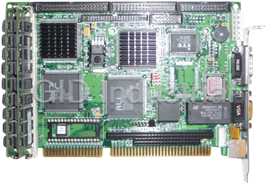
AAEON SBC-356

Description
Half-size All-in-one 386SX-40 CPU card
Part Number
SBC-356
Price
Request Quote
Manufacturer
AAEON
Lead Time
Request Quote
Category
Single Board Computers
Specifications
System Chipset
ALi M6117
Form Factor
Half-Size ISA
Video Chipset
C&T 65545
Datasheet

Extracted Text
SBC-356
Half-size All-in-one 386SX-40 CPU card
FCC STATEMENT
THIS DEVICE COMPLIES WITH PART 15 FCC RULES.
OPERATION IS SUBJECT TO THE FOLLOWING TWO
CONDITIONS: (1) THIS DEVICE MAY NOT CAUSE HARM-
FUL INTERFERENCE. (2) THIS DEVICE MUST ACCEPT
ANY INTERFERENCE RECEIVED INCLUDING INTERFER-
ENCE THAT MAY CAUSE UNDESIRED OPERATION.
THIS EQUIPMENT HAS BEEN TESTED AND FOUND TO
COMPLY WITH THE LIMITS FOR A CLASS "A" DIGITAL
DEVICE, PURSUANT TO PART 15 OF THE FCC RULES.
THESE LIMITS ARE DESIGNED TO PROVIDE REASON-
ABLE PROTECTION AGAINTST HARMFUL INTERFER-
ENCE WHEN THE EQUIPMENT IS OPERATED IN A
COMMERCIAL ENVIRONMENT. THIS EQUIPMENT
GENERATES, USES, AND CAN RADIATE RADIO
FREQENCY ENERGY AND , IF NOT INSTATLLED AND
USED IN ACCORDANCE WITH THE INSTRUCTION
MANUAL, MAY CAUSE HARMFUL INTERFERENCE TO
RADIO COMMUNICATIONS. OPERATION OF THIS
EQUIPMENT IN A RESIDENTIAL AREA IS LIKELY TO
CAUSE HARMFUL INTERFERENCE IN WHICH CASE
THE USER WILL BE REQUIRED TO CORRECT THE
INTERFERENCE AT HIS OWN EXPENSE.
Copyright Notice
This document is copyrighted, 1997, by AAEON Technology Inc.
All rights are reserved. AAEON Technology Inc. reserves the
right to make improvements to the products described in this
manual at any time without notice.
No part of this manual may be reproduced, copied, translated or
transmitted in any form or by any means without the prior written
permission of AAEON Technology Inc. Information provided in
this manual is intended to be accurate and reliable. However,
AAEON Technology Inc. assumes no responsibility for its use, nor
for any infringements upon the rights of third parties which may
result from its use.
AMI, Analog Device, Award, Burr-Brown, Carray, DR-DOS IBM,
AT, INM XT, Personal System/2, PS/2, Micro Channel, PC-DOS,
Inlog, Jactech, Microsoft, MS-DOS, NEC, Singular and TI are
Registered trademarks.
Part No. 2007356000 1st Edition
Printed in Taiwan Oct 1997
Packing list
Before you begin installing your card, please make sure that the
following materials have been shipped:
• 1 SBC-356 CPU card
• 1 6-pin mini-DIN dual outlet adapter for keyboard and PS/2
mouse
• 1 Hard disk drive (IDE) interface cable (40 pin)
• 1 Floppy disk drive interface cable (34 pin)
• 1 parallel port adapter (26-25 pin) and COM port (10-9 pin)
adapter kit
• 1 utility disk with VGA utility programs and drivers
If any of these items are missing or damaged, contact your
distributor or sales representative immediately.
Contents
1 General Information ........................... 1
Introduction ............................................................................ 2
Specifications .......................................................................... 3
Board layout ........................................................................... 5
Card dimensions ..................................................................... 6
2 Installation ........................................... 7
Jumpers and connectors ........................................................ 8
Locating jumpers and connectors ....................................... 10
Setting jumpers ...................................................................... 11
Safety precautions ................................................................ 12
Installing DRAM (SIMMs) .................................................. 13
Watchdog timer setup(JP9, JP14) ....................................... 14
PS/2 Mouse Setup (JP8) ....................................................... 17
Flash EPROM Selection (JP15) ........................................... 17
COM4 Communication setup (JP1, JP12, JP13) .............. 18
IDE Hard Disk I/F (CN10) ................................................... 19
Floppy disk Connector I/F (CN7) ....................................... 20
Serial communication I/F
(CN17, CN14, CN15, CN16, CN 12) ................................... 21
Parallel Port I/F (CON2) ...................................................... 23
VGA Monitor I/F (CN18) .................................................... 24
Flat Panel I/F (CN11) ............................................................ 25
Cable and switch connections
(CN1, CN3, CN4, CN5, CN19, CN21, CN6) ...................... 26
DiskOnChip Installation (U9, JP11) ................................... 27
3 AMIBIOS Setup .................................... 29
General information ............................................................. 30
Standard CMOS Setup ........................................................ 31
Advanced CMOS Setup ....................................................... 33
Advanced Chipset Setup ...................................................... 40
Change Suppervisor Password ............................................ 41
Auto Configuration with Optimal settings ......................... 41
Auto Configuration with Fail Safe settings ........................ 41
Save Settings and Exit .......................................................... 41
Exit Without saving .............................................................. 42
4 SVGA Setup ......................................... 43
Windows 3.1 .......................................................................... 44
Driver installation - Windows Setup ........................................ 44
DOS ....................................................................................... 45
SOFTWARE UTILITIES ...................................................... 47
The CHIPSCPL utility program ............................................. 47
Installing the utility .................................................................. 47
Howto use the uitlity ............................................................... 47
A Watchdog Timer Demo Program .... 49
B Installing PC/104 Modules ................. 51
Installing PC/104 modules ................................................... 52
C LCD Display BIOS Configuration........ 55
1
GeneraI
Information
This chapter provides background
information for the SBC-356.
Sections include:
· Card specifications
· Board layout
Chapter 1 General Information 1
CHAPTER
Introduction
The SBC-356 is an all-in-one CPU card that intergrates VGA
display and Disk-On-Chip card. The SBC-356 is a half-sized card
that is based on the 386SX CPU running at 40MHz and supports
up to 32 MB of Fast Page DRAM. The card has an on-board
Watch-Dog timer, a Buzzer, and battery-backed Real Time Clock.
It comes with AMI BIOS which is mapped to the upper 64K of
memory.
The SBC-356 provides a floppy disk controller, an IDE disk
controller, four high speed serial prots (RS-232/422/485) and
one Multi-mode parallel port (ECC/EPP/ECP). The SBC-356 is
also equipped with VGA controller. It uses C&T F65545 ISA-bus
VGA controller which provides a flat panel I/F (interface) to
support panel displays.
For applications that require Solid State Disk (SSD) memory, the
SBC-356 is equipped with one 32-pin DIP IC socket which can
accommodate DiskOnChip Solid State Disk memory. The SBC-
356 supports from 2MB up to 24MB of SSD memory.
2 SBC-356 User’s Manual
Specifications
· CPU: 386SX 40 MHz
· Bus interface: ISA (PC/AT) bus
· Data Bus: 16 bit
· Chipset: ALI M6117B (Embedded CPU-386SX)
· RAM memory: Fast Page DRAM 512KB to 16 MB with access
time 70 ns or faster. Uses two 72 pin SIMM sockets
· Dsiplay controller: C&T F65545 ISA-bus VGA controller
· Video memory: two 256k*16 DRAM (1MB) and one 256K*16
DRAM(512KB) used for improving performance with color DSTN
panels
· IDE HDD interface: One primary IDE hard disk drive interface
supports up to two IDE HDDs
· Floppy disk drive interface: One floppy disk drive interface
supports up to two floppy disk drives, 5.25"(360KB and 1.2MB) and /
or 3.5" (720KB, 1.44 and 2.88MB)
· Parallel port: One Multi-mode Parallel port(ECC/EPP/ECP
models)
· Serial port: Four high speed serial ports. Three RS-232 and one
RS-232/RS-422/RS-485
· Real time clock: Dallas DS12B887
· Watchdog timer: Jumper configured time interval: 1, 2, 10, 20, 110,
120 seconds
· PC/104 connector: 104 pins for 16-bit bus. Supports PC/104
modules such as Flash/RAM/ROM disk modules and/or PCMCIA
modules
· Solid State Disk (SSD) interface: One 32-pin DIP socket supports
M-system Disk-On-Chip 2000 series, memory capacity from 1MB to
24MB.
· DMA channels: 7
Chapter 1 General Information 3
· Interrupt channels: 15
· Keyboard interface: Yes
· PS/2 mouse support: Yes
· Voltage requirements: +5V, +12V and -12V
· Operating temperature: +0°C to 60°C
· Storage temperature: -25°C to +85°C
· Operating humidity range: 0 to 90% non-condensing
· Storage humidity range: 0 to 90% non-condensing
· Weight (without memory): 260g
· Dimensions: 19.0(L)*12.5(W)*2.5(H)cm
4 SBC-356 User’s Manual
Board layout
Chapter 1 General Information 5
Card dimensions
19.00
80.65
112.00
122.00
4.50
6 SBC-356 User’s Manual
185.00
26.00
73.66
SBC-356 386 CPU CARD WITH VGA/PANEL REV. A1
2
Installation
This chapter describes how to set up the
SBC-356 hardware, including instruc-
tions on setting jumpers and connecting
peripherals, switches and indicators. Be
sure to read all safety precautions before
you begin the installation procedure.
Chapter 2 Hardware Configuration 7
CHAPTER
Jumpers and connectors
Connectors on the board link it to external devices such as hard
disk drives, a keyboard or floppy drives. In addition, the board has
a number of jumpers that allows you to configure your system to
suit your application. The table below lists the function of each of
the board jumpers and connectors.
Name Function
CN1 Power connector
CN2 Printer I/F connector
CN3 External reset connector
CN4 Key lock
CN5 Speaker
CN6 HDD LED (indicator)
CN7 FDD I/F connector
CN8 PC/104 I/F (XT Bus)
CN9 PC/104 I/F (AT Bus)
CN10 HDD connector (Primary)
CN11 LCD panel I/F connector
CN12 Serial I/F #4 (RS-422/485)
CN14 Serial I/F #2 (RS-232)
CN15 Serial I/F #3 (RS-232)
CN16 Serial I/F #4 (RS-232)
CN17 Serial I/F #1 connector
CN18 VGA I/F connector
CN19 Keyboard connector
CN21 Keyboard/Mouse connector
U9 Disk On Chip socket
SM1-2 System DRAM socket
JP1 COM4 Communication I/F
JP8 PS/2 interrupt (IRQ12)
JP9 Watch-dog timer out active
JP11 Disk On Chip address selection (DiskOnChip
memory)
8 SBC-356 User’s Manual
JP12 RS-422/485 RX control
JP13 RS-422/485 TX control
JP14 Watch-Dog Timer Timeout
JP15 Flash EPROM Select
Chapter 2 Hardware Configuration 9
MEGA-KB-H-Q
Locating jumpers and connectors
CN1
CN18 CN17 CN21
CN12
CN14 CN15
CN16
CN8
CN11
CN9
CN10
CN7
JP11
CN6
JP9
CN4
CN5
JP8
CN3
JP1
CN2
CN19
SM1, SM2
10 SBC-356 User’s Manual
JP15
JP12
JP13
BIOS
JP14
U9
DALLAS
DiskOnChip
DS12887A
SBC-356 386 CPU CARD WITH VGA/PANEL REV. A1
ALI
M5113
ALI
M6117B
UMC
UM8669F
14.3C73
CHIPS
F65545 B2
Setting jumpers
You configure your card to match the needs of your application by
setting jumpers. A jumper is the simplest kind of electric switch.
It consists of two metal pins and a small metal clip (often
protected by a plastic cover) that slides over the pins to connect
them. To “close” a jumper you connect the pins with the clip. To
“open” a jumper you remove the clip. Sometimes a jumper will
have three pins, labeled 1, 2 and 3. In this case you would connect
either pins 1 and 2 or 2 and 3.
3
2
1
Open Closed Closed 2-3
The jumper settings are schematically depicted in this manual as
follows:
1 2 3
Open Closed Closed 2-3
A pair of needle-nose pliers may be helpful when working with
jumpers.
If you have any doubts about the best hardware configuration for
your application, contact your local distributor or sales represen-
tative before you make any changes.
Generally, you simply need a standard cable to make most
connections.
Chapter 2 Hardware Configuration 11
Safety precautions
Warning! Always completely disconnect the power cord
from your chassis whenever you are working on
it. Do not make connections while the power is
on because sensitive electronic components can
be damaged by the sudden rush of power. Only
experienced electronics personnel should open
the PC chassis.
Caution! Always ground yourself to remove any static
charge before touching the CPU card. Modern
electronic devices are very sensitive to static
electric charges. Use a grounding wrist strap at
all times. Place all electronic components on a
static-dissipative surface or in a static-shielded
bag when they are not in the chassis.
12 SBC-356 User’s Manual
Installing DRAM (SIMMs)
The SBC-356 are sold without system memory and disk on chip
memory. Memory must be installed prior to using the SBC-356.
The SBC-356 has 2 SIMM (Single In-line Memory Module)
DRAM module sockets. Each socket will accommodate a 72 pin
DRAM module - 1MB, 4MB or 16MB. The memory access time
should be 70ns or less. The SBC-356 can also accommodate
memory modules with parity check bit. EDO DRAM memory
modules are not supported by SBC-356.
Install memory as appropriate at locations SIMM1 - SIMM2.
SSS1 S1S2 MMM MM11 1 SSS2 S2Sy MMMMM22 TTTy Ty ToooootttttaaaaalllllMMMMMeeeeemmmmmooooorrrrryy
1B MB 1M
1BMB 1B M 2M
4B MB 4M
4BMB 4B M 8M
1B 6MB 16M
1B6MB 1B 6M 32M
Chapter 2 Hardware Configuration 13
Watchdog timer setup(JP9 and JP14)
The watch-dog timer is a circuit that should be refreshed periodi-
cally. If it is not refreshed within a certain time, the watch-dog
timer will automatically reset the system. This prevents a system
from hanging indefinitely. When the Watch-dog tmer is enabled,
the user must constantly refresh the Watch-dog timer within a
certain time (Eg. 10 seconds). If the user falls to do so, the
watch-dog timer will automatically reset the system or issue a
non-maskable interrupt (NMI).
JP9 determines the watch-dog timer function, it can disable the
watch-dog timer or connect watch-dog timer to reset trigger or
NMI trigger.
Watch-dog Timer Selection(JP9)
Disable Watch-dog timer
1
2
3
System Reset (Default)
1
2
3
NMI
1
2
3
14 SBC-356 User’s Manual
JP14 determines the time period of the watch-dog timer. It can
be disabled or set as 1 second, 2 seconds, 10 seconds, 20
seconds, 110 seconds or 120 seconds.
Watch-Dog Timer Time Out Selection(JP 14)
1 second 2 seconds
8 8
2 2
7 7
1 1
10 seconds(Default) 20 seconds
8
2 8
2
7
1 7
1
110 seconds 120 seconds
2 8 8
2
1 7 7
1
Chapter 2 Hardware Configuration 15
When the power of SBC-356 is turned on, the Watch-dog timer is
disabled. The watch-dog timer can be enabled by reading the
Watch-dog timer enable/refresh control port (443H), and
disabled by reading the Watch-dog timer disable control port
(43H). After the Watch-dog timer is enabled, the user must
constandly refresh the Watch-dog timer by reading the Watch-dog
timer enable/refresh port (443H) every 1, 2, 10, 20, 110 or 120
seconds. If the user fails to do so or the system hangs, the watch-
dog timer will automatically reset the system or issue a NMI
(Non-maskable interrupt).
Port Direction Function
443H I/O Read Enable Watch-Dog Timer
Refresh Watch-Dog Timer
43H I/O Read Disable Watch-Dog Timer
Please refer to Appendix A for a Watchdog timer demo program.
16 SBC-356 User’s Manual
PS/2 Mouse Setup (JP8)
JP8 determines the PS/2 mouse interrupt signal. The PS/2 mouse
uses IRQ12. If you do not use PS/2 mouse and wish to assign
IRQ12 for other purposes, you may change JP8 to disconnect PS/
2 interrupt from IRQ12.
PS/2 Interrupt select (JP8)
No interrupt for PS/2
IRQ12 (Default)
Flash EPROM Selection (JP15)
JP15 determines the programming voltage of Flash EPROM
BIOS. The SBC-356 BIOS provides plug and play function, it can
automatically reload system configuration to the system BIOS.
The SBC-356 BIOS can use variety Flash EPROM, JP15 must set
according to the Flash EPROM used.
Flash EPROM select(JP15)
Vpp=Vcc (Default) 1 3
Vpp=12V 1 3
Chapter 2 Hardware Configuration 17
COM4 Communication Setup
(JP1, JP12, JP13)
COM4 can also be assigned as RS-422 or RS-485 I/F. Short JP1
to assign COM4 as RS-422/RS-485 I/F, or otherwise assign
COM4 as RS-232 I/F.
COM4 communication select (JP1)
RS-422/RS-485 I/F (Default)
RS-232 I/F
When COM4 is assigned as RS-422/RS-485 I/F, JP12 and JP13
determine the RS-485 transmit and receive enable signals.
COM4 RS-422/RS-485 RX control (JP12)
RX is always enable (Default) 2 5
1 6
RX is enabled if Port 2EFH D1=1 2 5
1 6
RX is always disabled
2 5
1 6
COM4 RS-422/RS-485 TX control (JP13)
TX is always enable (Default) 2 8
1 7
TX is enabled if -RTS=0
2 8
1 7
TX is enabled if Port 2EFH D0=1
2 8
1 7
TX is always disabled
2 8
1 7
18 SBC-356 User’s Manual
IDE Hard Disk I/F (CN10)
The SBC-356 provides a 40-pin DIL box header connector
(CN10) for the IDE hard disk interface. The IDE hard disk
interface supports two IDE hard disk drives.
This I/F can be enabled or disabled by BIOS CMOS Setup
settings. If you want to use a ESDI or SCSI interface or you want
to use another IDE interface card, you must disable the BIOS
option " Onboard IDE ".
IDE hard disk connector (CN10)
Pin Signal Pin Signal
1 Reset 2 Ground
3 D07 4 D08
5 D06 6 D09
7 D05 8 D10
9 D04 10 D11
11 D0 3 12 D12
13 D02 14 D13
15 D01 16 D14
17 D00 18 D15
19 Ground 20 N.C.
21 N.C. 22 Ground
23 IOW- 24 Ground
25 IOR- 26 Ground
27 N.C. 28 Bale
29 N.C. 30 Ground
31 PinInterrupt 32 IOCS16-
33 SA1 34 N.C.
35 SA0 36 SA2
37 HDC CS0- 38 HDC CS1-
39 HDD Active 40 Ground
Chapter 2 Hardware Configuration 19
Floppy Disk Connector I/F (CN7)
The SBC-356 provides a 34-pin DIL box header connector (CN7)
for the floppy disk interface. This floppy disk interface supports
two 360KB (5.25"), 720KB (3.5"), 1.2MB (5.25"), 1.44MB (3.5")
and 2.88MB (3.5") floppy disk drive.
This floppy disk interface can be enabled or disabled by BIOS
CMOS Setup setting. If you want to use another floppy disk
interface card, you must disable the floppy disk interface on the
SBC-356.
Floppy Disk Drive Interface (CN7)
Pin Signal Pin Signal
1 Ground 2 Reduce Write Current-
3 Ground 4 N.C.
5 Ground 6 N.C.
7 Ground 8 Index-
9 Ground 10 Motor Enable A-
11 Ground 12 Driver Select B-
13 Ground 14 Driver Select A-
15 Ground 16 Motor Enable B-
17 Ground 18 Direction-
19 Ground 20 Step-
21 Ground 22 Write Data-
23 Ground 24 Write Gate-
25 Ground 26 Track 0-
27 Ground 28 Write Protect-
29 Ground 30 Read data-
31 Ground 32 Side 1 Select-
33 Ground 34 Disk Change-
20 SBC-356 User’s Manual
Serial Communication I/F
(CN17, CN14, CN15, CN16, CN12)
The SBC-356 provides four serial communication I/F. These
interfaces can be enabled, disabled and COM port assignable
individually. COM1, COM2 and COM3 are RS-232 I/F, COM4
can be assigned as RS-232 I/F or RS-422/RS-485 I/F.
The following are the pin assignments:
PIN COM1 COM2 COM3 COM4 Signal
CN17 CN14 CN15 CN16 (RS-232)
1 DCD DCD DCD DCD Data carry detect
2 RX RX RX RX Receive data
3 TX TX TX TX Transmit data
4 DTR DTR DTR DTR Data terminal ready
5 GND GND GND GND Ground
6 DSR DSR DSR DSR Data set ready
7 RTS RTS RTS RTS Request to send
8 CTS CTS CTS CTS Clear to send
9 RI RI RI RI Ring indicator
10 NC NC NC Not connected
CN17 is a male D-type connector, CN14, CN15 and CN16 are 10
pin dual-in-line box header connector.
COM4 can also be assigned as RS-422 or RS-485 I/F.
Chapter 2 Hardware Configuration 21
If COM4 is assigned as RS-422/Rs-485 I/F, CN12 is the COM4
connector, it is a dual-in-line box header connector.
Pin COM4 Signal
CN12 (RS-422/RS-485)
1 TX- Transmit data
2 TX+ Transmit data
3 RX+ Receive data
4 RX- Receive data
5 GND Ground
6 RTS- Request to send
7 RTS+ Request to send
8 CTS+ Clear to send
9 CTS- Clear to send
10 NC Not connected
22 SBC-356 User’s Manual
Parallel Port I/F (CON2)
The SBC-356's parallel port can be enabled or disabled or
configured as a different I/O address, mode (Standard, EPP or
ECP), IRQ channel and DMA channel. All parallel port configu-
rations can be set at BIOS CMOS Setup.
Parallel Port I/F (CN2)
Pin Signal Pin Signal
1 Strobe- 14 Auto FF-
2 D0 15 Error-
3 D1 16 Initialization-
4 D2 17 Printer Select In-
5 D3 18 Ground
6 D4 19 Gronnd
7 D5 20 Ground
8 D6 21 Ground
9 D7 22 Ground
10 Acknowledge- 23 Ground
11 Busy 24 Ground
12 Paper Empty 25 Ground
13 Printer Select 26 N.C.
Chapter 2 Hardware Configuration 23
VGA Monitor I/F (CN18)
The SBC-356 is equipped with an VGA I/F(CN18). CN18 is a 15
pin D-sub type connector.
VGA Monitor I/F (CN18)
Pin number CN18
1R
2G
3B
4NC
5 GROUND
6 GROUND
7 GROUND
8 GROUND
9 GROUND
10 GROUND
11 NC
12 NC
13 Hsync
14 Vsync
15 NC
24 SBC-356 User’s Manual
Flat Panel I/F (CN11)
The SBC-356 provides a 44-pin box header connector (CN11) for
Flat panel.
SBC-356 Flat panel display connector
Pin Function Pin Function
1 +12 V 2 +12 V
3 GND 4 GND
5 Vcc 6 Vcc
7 ENAVEE 8 GND
9P0 10 P1
11 P2 12 P3
13 P4 14 P5
15 P6 16 P7
17 P8 18 P9
19 P10 20 P11
21 P12 22 P13
23 P14 24 P15
25 P16 26 P17
27 P18 28 P19
29 P20 30 P21
31 P22 32 P23
33 GND 34 GND
35 SHFCLK 36 FLM
37 M 38 LP
39 GND 40 ENABKL
41 GND 42 ASHFCLK
43 V 44 V
cc cc
Chapter 2 Hardware Configuration 25
Cable and switch connections
(CN1, CN3, CN4, CN5, CN19, CN21, CN6)
Pin Power Reset Switch Keylock
(CN1) (CN3) (CN4)
1 +5V Reset Power
2 GND Gnd Key
3 GND ***** Gnd
4 +12v ***** Lock
5 ***** ***** Gnd
6 ***** ***** *****
7 ***** ***** *****
8 ***** ***** *****
Pin Speaker Internal keyboard External Keyboard HDD LED
(CN5) (CN19) (CN21) (CN6)
1 Speaker Clock Clock -R/W IDE
2 N/C Data Data Pull high
3 GND N/C N/C *****
4 +5V GND Gnd *****
5 ***** +5V +5V *****
CN21 is the keyboard connector. A converter cable is included to
adapt the 5-pin keyboard DIN connector on the keyboard to the 6-
pin Mini-DIN connector. Connect the keyboard converter cable
to CN21 and connect the other end to the keyboard.
26 SBC-356 User’s Manual
DiskOnChip Installation (U9, JP11)
Please refer to the DiskOnChip manual for detailed information
on how to prepare the Disk On Chip function on the SBC-356.
To install DiskOnChip on the SBC-356, follow the instructions
below.
Step 1: Install the DiskOnChip Memory (DiskOnChip) in U9
sockets.
Step 2: Set JP11 for the memory address of DiskOnChip
memory.
JP11 determines the memory adddress of DiskOnChip memory.
If you have another add-on card in the system that uses the same
memory, neither the SBC-356 nor the add-on card will function
normally. In this case, please change the memory address.
DiskOnChip address select (JP11)
Disable D0000H-D7FFFH (32KB)
7 7
1 1
8
2 2 8
D8000H-DFFFFH (32KB) *E0000H-E7FFFH (32KB)
1 7
1 7
8 2 8
2
E8000H-EFFFFH (32KB)
1 7
2 8
* Default
Chapter 2 Hardware Configuration 27
28 SBC-356 User’s Manual
3
AMIBIOS Setup
This chapter describes how to set BIOS
configuration data.
CHAPTER
General information
AMIBIOS Setup configures system information that is stored in
CMOS RAM.
Starting AMIBIOS setup
As POST executes, the following appears;
Hit if you want to run SETUP
Press to run AMIBIOS setup.
AMIBIOS main menu
The AMIBIOS setup screen appears as follows:
AMIBIOS SETUP — BIOS SETUP UTILITIES
(C) 1995 American Megatrends, Inc. All Rights Reserved
Standard CMOS Setup
Advanced CMOS Setup
Advanced Chipset Setup
Change User Password
Change Supervisor Password
Change Language Setting
Auto Configuration with Optimal Settings
Auto Configuration with Fail Safe Settings
Save Settings and Exit
Exit Without Saving
Standard CMOS setup for changing time, date, hard disk type, etc.
ESC: Exit :Sel F2/F3: Color F10: Save & Exit
¯-
30 SBC-356 User’s Manual
Standard CMOS Setup
The AMIBIOS Setup options described in this section are
selected by choosing the Standard CMOS Setup from the AMI-
BIOS Setup main menu selection screen, as shown below.
The Standard CMOS Setup screen appears:
AMIBIOS SETUP — STANDARD CMOS SETUP
(C) 1995 American Megatrends, Inc. All Rights Reserved
Date (mm/dd/yyyy): Wed Aug 21, 1996
Time (hh/mm/ss): 12: 19: 46
Floppy Drive A: 1.44 MB 3½
Floppy Drive B: Not Installed
LBA Blk PIO 32Bit
Type Size Cyln Head WPcom Sec Mode Mode Mode Mode
Pri Master : AUTO On On AUTO Off
Pri Slave : AUTO On On AUTO Off
Boot Sector Virus Protection Disabled
Month: Jan - Dec Esc: Exit :Sel
¯-
Day: 01-31 PgUp/PgDn: Modify
Year: 1901 -2099 F2/F3: Color
Date, Day and Time Configuration
The current values for each category are displayed. Enter new
values through the keyboard.
Floppy A, Floppy B
Select the appropriate specifications to configure the type of
floppy drive that is attached to the system: 360 KB 5¼", 1.2 MB
5¼", 720 KB 3½", and/or 1.44 MB 3½". The settings have not
been pre-installed.
Chapter 3 AMIBIOS Setup 31
Master Disk, Slave Disk
Select the appropriate values to configure the hard disk type you
are using for the master and the slave. Available types are 1~46,
USER, AUTO, Not Installed, and CDROM. The settings have not
been preinstalled.
Boot Sector Virus Protection
Enabling this option allows the system to issue a warning when
any program (or virus) issues a disk format command or attempts
to write to the boot sector of the hard disk drive. Further confir-
mation is required before accessing this particular section of the
hard disk drive.
32 SBC-356 User’s Manual
Advanced CMOS Setup
Select the Advanced CMOS Setup from the AMIBIOS Setup main
menu to enter Advanced setup.
The Advanced Setup options described in this section are the
standard options as shown on the following screen. The following
configurations are based on manufacture's default settings.
AMIBIOS SETUP — ADVANCED CMOS SETUP
(C) 1995 American Megatrends, Inc. All Rights Reserved
Available Options:
Quick Boot Enabled
Disabled
BootUp CPU Speed High
Enabled
BootUp Sequence A:,C:
BootUp Num-Lock On
Floppy Drive Swap Disabled
Floppy Drive Seek Disabled
Mouse Support Enabled
Typematic Rate Fast
System Keyboard Present
Password Check Setup
Parity Check Disabled
Wait For 'F1' If Error Enabled
Hit 'DEL' Message Display Enabled
System BIOS Cacheable Enabled
Hard disk Delay Disabled
C000, 32k Shadow Enabled
C800, 32k Shadow Disabled
D000, 32k Shadow Disabled
D800, 32k Shadow Disabled
E000, 32k Shadow Disabled
E800, 32k Shadow Disabled
Onboard IDE Enabled
Onboard FDC Enabled
Onboard Serial Port1 3F8
Onboard Serial Port2 2F8
Onboard Serial Port3 3E8
Onboard Serial Port3 IRQ 9
Onboard Serial Port4 2E8
Onboard Serial Port4 IRQ 5
Onboard Parallel port 378
Parallel port Mode SPP
ECP DMA DMA 3
Parallel Port IRQ IRQ 5 ESC: Exit :Sel
¯-
PgUp/PgDn: Modify
Flat Panel Display Type 12BTFT NEC 64
F2/F3: Color
DISPLAY MODE BOTH
Chapter 3 AMIBIOS Setup 33
Quick Boot
Set this option to Enabled to instruct AMIBIOS to boot quickly
when the computer is powered on. This option replaces the old
Above 1 MB Memory Test Advanced Setup option.
Setting Description
Disabled AMIBIOS test all system memory. AMIBIOS waits up
to 40 seconds for a READY signal from the IDE hard
disk drive. AMIBIOS waits for .5 seconds after sending
a RESET signal to the IDE drive to allow the IDE drive
time to get ready again. AMIBIOS checks for a
key press and runs AMIBIOS Setup if the key has
been pressed.
Enabled AMIBIOS does not test system memory above 1 MB.
AMIBIOS does not wait up to 40 seconds for a
READY signal from the IDE hard disk drive. If a
READY signal is not received immediately from the
IDE drive, AMIBIOS does not configure that drive.
AMIBIOS does not wait for .5 seconds after sending a
RESET signal to the IDE drive to allow the IDE drive
time to get ready again.
You cannot run AMIBIOS Setup at system boot,
because there is no delay for the Hit to run
Setup message.
Boot Up CPU Speed
This option sets the CPU speed when the computer boots.
Boot Up Sequence
This option sets the sequence of boot drives (floppy drive A:, or
hard disk drive C:) that the AMIBIOS attempts to boot from after
AMIBIOS POST completes.
Boot Up Num Lock
Set this option to Off to turn the Num Lock key off when the
computer is booted so you can use the arrow keys on both the
numeric keypad and the keyboard.
34 SBC-356 User’s Manual
Floppy Drive Swap
Set this option to Enabled to permit drives A: or B: to be
swapped. The settings are Enabled or Disabled.
Floppy Drive Seek
Set this option to Enabled to specify that floppy drive will
perform a Seek operation at system boot. The settings are
Enabled or Disabled.
Mouse Support
When this option is set to Enabled, AMIBIOS supports a PS/2-
type mouse. The settings are Enabled or Disabled.
Typematic Rate
This option specifies the typematic rate of a keyboard.
System Keyboard
This option specifies that a keyboard is attached to the computer.
The settings are Present or Absent.
Primary Display
This option specifies the type of display monitor and adapter
in the computer. The settings are Mono, CGA40x25, CGA80x25,
VGA/EGA, or Absent.
Password Check
This option enables password checking every time the computer
is powered on or every time AMIBIOS Setup is executed. If
Always is chosen, a user password prompt appears every time the
computer is turned on. If Setup is chosen, the password prompt
appears as AMIBIOS is executed.
Parity Check
Set this option to Enabled to check the parity of all system
memory. The settings are Enabled or Disabled.
Chapter 3 AMIBIOS Setup 35
OS/2 Compatible Mode
Set this option to Enabled to permit AMIBIOS to run with IBM
OS/2. The settings are Enabled or Disabled.
Wait for ’F1’ if Error
AMIBIOS POST error messages are followed by:
Press if you want to run Setup
from appearing on the first AMIBIOS screen when the computer
boots. The settings are Enabled or Disabled.
System BIOS Cacheable
When this option is set to Enabled, the contents of the F000h
system memory segment can be read from or written to the cache
memory. The contents of the F000h memory segment are always
copied from the BIOS ROM to system RAM for faster execution.
The settings are Enabled or Disabled.
Hard disk Delay
The settings of this option are Disabled, 3 sec, 5 sec, 10 sec, 15
sec.
36 SBC-356 User’s Manual
C000,32k Shadow D800,32k Shadow
C800,32k Shadow E000,32k Shadow
D000,32k Shadow E800,32k Shadow
These options control the location of the contents of the 32KB of
ROM beginning at the specified memory location. If no adapter
ROM is using the named ROM area, this area is made available to
the local bus. The settings are:
Setting Description
Enabled The contents of C000h - C7FFh are written to the
same address in system memory (RAM) for faster
execution.
Cached The contents of the named ROM area are written to
the same address in system memory (RAM) for faster
execution, if an adapter ROM will be using the named
ROM area. Also, the contents of the RAM area can be
read from and written to cache memory.
Disabled The video ROM is not copied to RAM. The contents of
the video ROM cannot be read from or written to cache
memory.
Onboard IDE
This option specifies whether the onboard IDE controller is
enabled.
Chapter 3 AMIBIOS Setup 37
Onboard FDC
This option enables or disables the floppy drive controller on the
CPU board.
Onboard Serial Port 1
Onboard Serial Port 2
Onboard Serial Port 3
Onboard Serial Port 4
This option enables a serial port on the CPU board and specifies
the base I/O port address for that serial port.
Onboard Serial Port 3 IRQ
Onboard Serial Port 4 IRQ
This option specify an IRQ to a serial port.
OnBoard Parallel Port
This option enables the parallel port on the CPU board and
specifies the parallel port base I/O port address. The settings are
Disabled, 378h, 278h, 3BCh.
Parallel Port Mode
This option specifies the parallel port mode. ECP and EPP are
both bidirectional data transfer sechemes that adhere to the IEEE
P1284 specification. The settings are:
Setting Description
EPP The parallel port can be used with devices that adhere
to the Enhanced Parallel Port (EPP) specification.
EPP uses the exiting parallel port signals to provide
asymmetric bidirectional data transfer driven by the
host device.
ECP The parallel port can be used with devices that adhere
to the Extended Capabilities Port (ECP) specification.
ECP uses the DMA protocol to achieve transfer rates
of approximately 2.5 Mbs. ECP provides symmetric
bidirectional communlations.
EPP&ECP Use this option to support both EPP and ECP on
the parallel port.
38 SBC-356 User’s Manual
Parallel Port IRQ
IRQ7 is used for the Parallel Port(LPT 1). The IRQ can be
changed to IRQ5, or auto-selected(Auto) .
Flat Panel Display Type
This option specifies the type of flat panel display the BIOS will
support.
Please refer to Appendix C for more information.
Display Mode
This option specifies the mode of display the BIOS will support.
Chapter 3 AMIBIOS Setup 39
Advanced Chipset Setup
Select the Advanced Chipset Setup from the AMIBIOS Setup
main menu to enter the Chipset Setup. The following configura-
tions are based on manufacture's default settings.
This section allows you to configure the system based on the
specific features of the installed chipset. This chipset manages
bus speeds and access to system memory resources, such as
DRAM and the external cache. It also coordinates communica-
tions between the conventional ISA bus and the PCI bus. It must
be stated that these items should never need to be altered. The
default settings have been chosen because they provide the best
operating conditions for your system.
AMIBIOS SETUP — ADVANCED CHIPSET SETUP
(C) 1995 American Megatrends, Inc. All Rights Reserved
AT Bus Clock 14. 318/2
Available Options:
Slow Refresh 120 us
Disable
Memory Remap Enabled
Enabled
RAS Precharge time 1.5T
RAS Active Time Insert wait Disable
CAS Precharge Time Insert Wait Disable
Memory Write Insert Wait Disable
Memory Miss Read Insert Wait Disable
ISA I/O High Speed Enabled
ISA Memory High Speed Enabled
ISA Write cycle end Insert Wait Enabled
I/O Recovery Enabled
I/O Recovery Period 3.75 us ESC: Exit :Sel
¯-
On-Chip I/O Recovery Enabled PgUp/PgDn: Modify
F2/F3: Color
16Bit ISA Insert Wait Enabled
40 SBC-356 User’s Manual
Change Supervisor Password
1) Select this option from the main menu
2) Enter the Password and Press
Frequently asked questions
How does Industrial Trading differ from its competitors?

Is there a warranty for the SBC-356?
Which carrier will Industrial Trading use to ship my parts?
Can I buy parts from Industrial Trading if I am outside the USA?
Which payment methods does Industrial Trading accept?
Why buy from GID?

Quality
We are industry veterans who take pride in our work

Protection
Avoid the dangers of risky trading in the gray market

Access
Our network of suppliers is ready and at your disposal

Savings
Maintain legacy systems to prevent costly downtime

Speed
Time is of the essence, and we are respectful of yours
Related Products
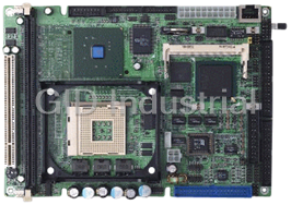
486DX5-133 Half-size CPU Card with LCD, Ethernet, & SSD
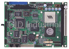
VIA C3 / Eden Low Power Processors
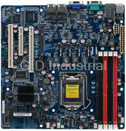
Compact Board with Intel Pentium 4/ Celeron Processors
Entry Level Intel Xeon Server Board, UDIMM RAM/VGA/GbE x 2 LAN/2 USB
High Performance Server Board with Dual Intel Xeon Processors, RDIMM/UDIMM/LRDIMM RAM, VGA, 2 GbE LA...
Request a Quote

The quote request has been received
Close

Facing challenges or have inquiries? Feel free to contact us!
Call Us +1-469-283-2440
What they say about us
FANTASTIC RESOURCE
One of our top priorities is maintaining our business with precision, and we are constantly looking for affiliates that can help us achieve our goal. With the aid of GID Industrial, our obsolete product management has never been more efficient. They have been a great resource to our company, and have quickly become a go-to supplier on our list!
Bucher Emhart Glass
EXCELLENT SERVICE
With our strict fundamentals and high expectations, we were surprised when we came across GID Industrial and their competitive pricing. When we approached them with our issue, they were incredibly confident in being able to provide us with a seamless solution at the best price for us. GID Industrial quickly understood our needs and provided us with excellent service, as well as fully tested product to ensure what we received would be the right fit for our company.
Fuji
HARD TO FIND A BETTER PROVIDER
Our company provides services to aid in the manufacture of technological products, such as semiconductors and flat panel displays, and often searching for distributors of obsolete product we require can waste time and money. Finding GID Industrial proved to be a great asset to our company, with cost effective solutions and superior knowledge on all of their materials, it’d be hard to find a better provider of obsolete or hard to find products.
Applied Materials
CONSISTENTLY DELIVERS QUALITY SOLUTIONS
Over the years, the equipment used in our company becomes discontinued, but they’re still of great use to us and our customers. Once these products are no longer available through the manufacturer, finding a reliable, quick supplier is a necessity, and luckily for us, GID Industrial has provided the most trustworthy, quality solutions to our obsolete component needs.
Nidec Vamco
TERRIFIC RESOURCE
This company has been a terrific help to us (I work for Trican Well Service) in sourcing the Micron Ram Memory we needed for our Siemens computers. Great service! And great pricing! I know when the product is shipping and when it will arrive, all the way through the ordering process.
Trican Well Service
GO TO SOURCE
When I can't find an obsolete part, I first call GID and they'll come up with my parts every time. Great customer service and follow up as well. Scott emails me from time to time to touch base and see if we're having trouble finding something.....which is often with our 25 yr old equipment.
ConAgra Foods