

 Manufacturers
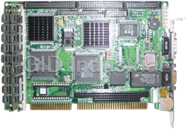
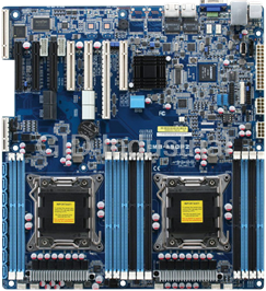
AAEON SBC-350A

Description
Half-size All-In-One 386SX-40 CPU Card
Part Number
SBC-350A
Price
Request Quote
Manufacturer
AAEON
Lead Time
Request Quote
Category
Single Board Computers
Specifications
System Chipset
ALi M1217
Form Factor
PC/104
Datasheet

Extracted Text
SBC-350A
Half-size All-In-One
386SX-40 CPU Card
Copyright Notice
This document is copyrighted, 1996. All rights are reserved. The
original company reserves the right to make improvements to the
products described in this manual at any time without notice.
No part of this manual may be reproduced, copied, translated or
transmitted in any form or by any means without the prior written
permission of the original company. Information provided in this
manual is intended to be accurate and reliable. However, the
original company assumes no responsibility for its use, nor for any
infringements upon the rights of third parties which may result
from its use.
Acknowledgments
The following references are the property of:
ALI is a trademark of ACER Labs, Inc.
AMD is a trademark of Advanced Micro Devices, Inc.
AMI is a trademark of American Megatrends Inc.
IBM and PC are trademarks of International Business Machines
Corporation.
Intel is a trademark of Intel corporation.
MS-DOS is a trademark of Microsoft Corporation.
SMC is a trademark of Standard Microsystems Corporation.
Part No. 2006350020 3rd Edition
Printed in Taiwan March 1996
Contents
Chapter 1 Hardware configuration.......................... 1
Introduction ............................................................................ 2
Specifications .......................................................................... 3
Locating components ............................................................. 4
SBC-350A board diagram ..................................................... 5
Jumpers and connectors ........................................................ 6
SIMM memory modules ........................................................ 6
Safety precautions .................................................................. 7
Jumper settings ...................................................................... 7
Card default setting .................................................................. 7
How to set jumpers ................................................................ 8
CPU clock and AT clock select (J2, J3, J4, J5) ..................... 8
Display type (J6) ................................................................... 8
Card dimensions .................................................................... 9
Chapter 2 Installation ............................................. 11
Initial inspection................................................................... 12
Chapter 3 Connecting peripherals ......................... 15
SBC-350A Card connectors ................................................ 16
Floppy drive connections (CN4) ......................................... 16
IDE hard drive connections (CN3) ..................................... 17
Parallel port (CN5).............................................................. 18
Keyboard connectors (CN6, CN12) .................................... 18
External switches and indicators ........................................ 19
Reset switch (J1) ................................................................. 19
Power LED and keylock (CN1) .......................................... 19
Hard disk drive LED (CN2) ................................................ 19
SBC power connector(CN9) ............................................... 20
Serial ports............................................................................ 20
RS-232 connections (CN10, CN11) .................................... 21
External speaker connector ................................................ 21
Chapter 4 Power-up ................................................ 23
Startup procedure ................................................................ 24
Chapter 5 BIOS diagnostics and SETUP ................... 25
POST (Power On Self Tests) ............................................... 26
System test and initialization ............................................... 26
System configuration verification ....................................... 26
Running the setup program ................................................ 27
BIOS setup main menu ........................................................ 28
Standard CMOS setup ......................................................... 29
Advanced CMOS setup ....................................................... 32
Advanced CHIPSET setup .................................................. 35
Auto configuration with BIOS defaults ............................... 36
Auto configuration with power-on defaults ........................ 36
Auto detect hard disk ........................................................... 36
Hard disk utility ................................................................... 36
Write to CMOS and exit/do not exit.................................... 36
Appendix A Programming the watchdog timer ... 37
Introduction .......................................................................... 38
Programming ....................................................................... 38
Demo program ..................................................................... 39
Appendix B Upgrading ............................................ 41
Installing DRAM (SIMMs) ................................................. 42
CPU upgrading..................................................................... 43
Installing PC/104 modules .................................................. 43
PC/104 Diagrams ................................................................ 45
1
Hardware
Configuration
This chapter gives background informa-
tion on the SBC-350A. It then shows you
how to configure the card to match your
application and prepare it for installation
into your PC.
Sections include:
• Card specifications
• Locating components
• Safety precautions
• Configuration – Jumper settings
Chapter 1 Hardware Configuration 1
CHAPTER
Introduction
The half-size SBC-350A comes equipped with a 80386SX-40 CPU.
Also included on-board are two serial RS-232 ports, a bi-directional
parallel port, an IDE hard disk drive interface, a floppy disk controller
and a watchdog timer. The watchdog timer ensures that the CPU will
be reset if it stops due to a program or EMI problem, allowing the
SBC-350A to be used in stand-alone systems or in unattended environ-
ments. The SBC-350A’s industrial-grade construction ensures continu-
ous, reliable operation in harsh industrial environments at temperatures
o o
up to 140 F (60 C).
We designed the SBC-350A with SBC (Single Board Computer)
applications in mind. It also incorporates a connector for PC/104
modules (Flat-panel/CRT VGA controller or Flash/RAM/ROM disk).
Built using CMOS technology, the SBC-350A consumes very little
power. Its four SIMM (Single In-line Memory Module) DRAM
sockets accept 256 KB, 1 MB or 4 MB SIMM modules for total on-
board memory of 1 to 16 MB.
You can also use this 4-layer CPU card to transform any system into a
16-bit 386 compatible computer, its all-in-one configuration freeing-up
valuable expansion slots. Its highly compact form and numerous
features make it an ideal cost/performance solution for high-end
commercial and industrial applications where high CPU speed and low
mean-time-to-repair are critical.
2 SBC-350A User's Manual
Specifications
�System
• CPU: 80386SX-40 MHz, 80486SLC-33 MHz
• Bus interface: ISA (PC/AT) bus
• System performance:
51.9 MHz with an 80386SX-40 MHz CPU
• Data bus: 16 bit
• DMA channels: 7
• Interrupt levels: 15
• Processing ability: 32 bit
• Bus speed: 8 MHz
• Chipset: ALI M1217-40
• Real-time clock/calendar:
Uses Dallas DS-12887 RTC or equivalent chip and quartz oscillator,
powered by a lithium battery for 10 years of data retention
�Memory
• RAM memory: 1 MB to 16 MB
Uses 256Kx9 (SIMM-256-7), 1Mx9 (SIMM-1000-7) or 4Mx9
(SIMM-4000-7) SIMMs with access time of 70 nsec. or less
• Shadow RAM memory: Support for system and video BIOS of up
to 256 KB in 32 KB blocks
�I/O
• IDE hard disk drive interface: Supports up to two IDE (AT bus)
hard disk drives. Can be enabled/disabled
• Floppy disk drive interface:
Supports up to two floppy disk drives, 5.25” (360 KB and 1.2 MB)
and/or 3.5” (720 KB, 1.44 MB and 2.88 MB). Can be enabled/
disabled
Chapter 1 Hardware Configuration 3
• Bi-directional parallel port: Configurable to LPT1, LPT2, LPT3 or
disabled. Standard female DB-25 connector provided
• Serial ports: Dual RS-232 serial ports with 16C550 compatible
UARTs (16-byte FIFO for speeds up to 115 Kbps). Ports can be
individually configured as COM1, COM2 or disabled
�Industrial features
• Watchdog timer:
The timeout interval is software programmable and can be set
between 2 to 30 sec.. Your program uses hex 043 and 443 to control
the watchdog and set the timeout period
• PC/104 Expansion:
A 64- and 40-pin, 16-bit bus connector for optional PC/104 modules
such as a Flash/RAM/ROM disk module and/or Flat-panel/CRT
VGA module
• Keyboard connectors: A 6-pin mini-DIN keyboard connector is
located on the mounting bracket for easy access. An external
keyboard adapter is also included. An on-board keyboard pin header
connector is also available.
�General
• Max power required: + 5 V @ 1.2 A
• Power supply voltage: +5 V (4.75 V to 5.25 V), +12 V, -12 V
o o
• Operating temperature: 32 to 140 F (0 to 60 C)
• Size: 7.3" (L) x 4.8" (W) (185 mm x 122 mm)
• Weight: 0.55 lbs. (250g)
• EMI: Pending
• MTBF: Pending
Locating components
This section identifies the location of the card's major components. It
also includes a list of the function of each of the card jumpers. The
figure on the following page gives an overall view of the card.
4 SBC-350A User's Manual
CN9 J6 CN13 COM1 COM2 CN12
CN6
MAX211
CN5
MAX211
SMC
FDC37C665 CN7,8
CN4 24MHz
ADVRNCED
ALI
MICRO
DEVICES M1217
TM
Am386 SX-40
J5,4,3,2
CN3
14.318
SIMM
J1
CN1
Sockets
CN2
SBC-350A PCB Layout
Chapter 1 Hardware Configuration 5
ODIN
OEC12C887
AMIBIOS
AMERICAN MEGATRENDS
386SX BIOS
TM
-2
AMIKEY
SBC-350A HALF-SIZE ISBC PC-386SX-40 REV:.A1
Jumpers and connectors
Connectors on the board link it to external devices such as hard disk
drives, a keyboard or PC/104 modules. In addition, the board has a
number of jumpers which you use to configure it for your application.
The table below lists the function of each of the board jumpers and
connectors. Later sections in this chapter give instructions on setting
jumpers and detailed information on each jumper setting. Chapter 3
gives instructions for connecting external devices to your card.
Jumpers and Connectors
Number Function Page
J1 Reset switch 19
J2,3,4,5 CPU clock and AT clock select 8
J6 Display type - mono, color 8
CN1 Power LED and Keylock 19
CN2 Hard disk driver activity LED 19
CN3 HDD connector 17
CN4 FDD connector 16
CN5 Parallel/printer connector 18
CN6 Keyboard connector 18
CN7/8 PC/104 expansion connector 43
CN9 SBC Power connector 20
CN10 COM1, RS-232 serial port 20
CN11 COM2, RS-232 serial port 20
CN12 Keyboard connector (6-pin mini DIN) 18
CN13 External speaker connector 21
SIMM memory modules
On the left end of the card (away from the mounting bracket) are the
four SIMM (Single In-line Memory Module) sockets which hold the
card’s DRAM memory. If you ordered DRAM SIMMs along with your
card, the SIMMs may already be installed. If not, you should install
them as described in Appendix B.
6 SBC-350A User's Manual
Safety precautions
Follow these simple precautions to protect yourself from harm and
your PC from damage.
1. To avoid electric shock always disconnect the power from your PC
chassis before you work on it. Don’t touch any components of the
CPU card or other cards while the PC is on.
2. Disconnect power before making any configuration changes. The
sudden rush of power as you connect a jumper or install a card may
damage sensitive electronic components.
3. Always ground yourself to remove any static charge before you
touch your CPU card. Be particularly careful not to touch the chip
connectors. Modern integrated electronic devices, especially CPUs
and memory chips, are extremely sensitive to static electric
discharges and fields. Keep the card in its anti-static packaging
when it is not installed in the PC and place it on a static dissipative
mat when you are working on it. Wear a grounding wrist strap for
continuous protection.
Jumper settings
This section tells how to set the jumpers to configure your card. It
gives the card default configuration and your options for each jumper.
After you set the jumpers and install the card, you will also need to run
the BIOS Setup program (discussed in Chapter 5) to configure the
serial port addresses, floppy/hard disk drive types and system operat-
ing parameters. Connections, such as hard-disk cables, appear in
Chapter 3.
Card default settings
We set the card’s jumpers at the factory for the most popular configu-
ration. If this configuration matches your needs, you may not need to
change the jumpers at all. The default configuration is as follows:
• CPU clock: 33 MHz. (J2, J3, J4, J5)
• Color display is attached (J6)
Chapter 1 Hardware Configuration 7
How to set jumpers
You configure your card to match the needs of your application by
setting jumpers. A jumper is the simplest kind of electric switch. It
consists of two metal pins and a small metal clip (often protected by a
plastic cover) that slides over the pins to connect them. To “close” a
jumper you connect the pins with the clip. To “open” a jumper you
remove the clip. Sometimes a jumper will have three pins, labeled 1, 2
and 3. In this case you would connect either pins 1 and 2 or 2 and 3.
You may find pair of needle-nose pliers useful for setting the jumpers.
If you have any doubts about the best hardware configuration for your
application, contact your local distributor or sales representative
before you make any changes.
CPU clock and AT clock select (J2, J3, J4, J5)
J2, J3, J4, and J5 are used to adjust the CPU clock and AT clock. Set
the CPU clock according to the base CPU speed. The default setting is
33 MHz.
CPU clock and AT clock select (J2, J3, J4, J5)
J2 J3 J4 J5
40 MHz
33 MHz
25 MHz
20 MHz
Display type (J6)
This jumper sets the display adapter type attached to your card. If you
are using a monochrome LCD or EL screen which uses a CGA, EGA,
VGA or other color display adapter, set J6 to color.
Monochrome Closed
Color Open (default)
8 SBC-350A User's Manual
¡¡ ¡¡ ¡¡ ¡¡
¡¡ ¡¡ ¡¡
¡¡
¡¡ ¡¡ ¡¡ ¡¡
¡¡ ¡¡ ¡¡ ¡¡
Card Dimensions
Unit = mm
Chapter 1 Hardware Configuration 9
185.00
178.00
73.66 26.00
PC/104 Module
D4x4
98.50
122.00
19.50
80.65 19.00
10 SBC-350A User's Manual
2
Installation
This chapter gives a general procedure for
installing your CPU card into an PC
chassis with an AT-compatible passive
backplane. For specific instructions,
consult the user’s manual for your chassis.
Chapter 2 Installation 11
CHAPTER
Initial Inspection
Before you begin installing your card, please make sure that the
following materials have been shipped:
• 1 SBC-350A CPU card
• 1 6-pin mini-DIN keyboard adapter
• 1 Hard disk drive (IDE) interface cable (40 pin)
• 1 Floppy disk drive interface cable (34 pin)
• 1 Parallel port adapter (26 pin) kit
• PC/104 Expansion connector converter (pin headers)
• PC/104 Module mounting supports
If any of these items are missing or damaged, contact your distribu-
tor or sales representative immediately.
We carefully inspected the SBC-350A mechanically and electrical-
ly before we shipped it. It should be free of marks and scratches
and in perfect working order on receipt.
As you unpack the SBC-350A, check it for signs of shipping
damage (damaged box, scratches, dents, etc.). If it is damaged or it
fails to meet specifications, notify our service department or your
local sales representative immediately. Also notify the carrier.
Retain the shipping carton and packing material for inspection by
the carrier. After inspection we will make arrangements to repair or
replace the unit.
Warning! Always completely disconnect the power cord
from your chassis whenever you are working on
it. Do not make connections while the power is
on, sensitive electronic components can be
damaged by the sudden rush of power. Only
experienced electronics personnel should open
the PC chassis.
12 SBC-350A User's Manual
Caution! Always ground yourself to remove any static
charge before touching the CPU card. Modern
electronic devices are very sensitive to static
electric charges. Use a grounding wrist strap at
all times. Place all electronic components in a
static-dissipative surface or static-shielded bag
when they are not in the chassis.
Before you begin installation, double check the jumper settings for
the card (described in Chapter 1). This could save you a lot of
troubleshooting time later. If you are not sure about the proper
setting, contact your local distributor or sales representative.
Install your CPU card as follows:
1. Remove power from the chassis and disconnect all power
cords. Follow all power-down procedures outlined in your
chassis user’s manual.
2. Remove the chassis cover, then detach the card hold-down
bracket. This bracket stretches across the top of each circuit
card to hold it securely in place.
3. Locate a free slot in the chassis. You can use any 16-bit (double
connector) slot. We suggest that you leave the maximum
amount of space between boards to improve cooling.
4. You may need to remove a block-off cover at the end of the
slot. Unscrew the cover and save the screw for use in Step 6.
5. Align the card square with the card-end guide slot and parallel
to the connector. Slide the card carefully into the connector.
6. Make sure the card is completely seated in the connector. Screw
the card I/O bracket to the case.
After you have installed the CPU card, you will need to attach the
connecting cables as described in the following chapter. When you
are finished installing the CPU card, replace the card hold-down
bracket you removed in Step 2, replace the chassis cover and
power-up your system.
Dimensions for SBC (Single Board Computer) installation appear
on page 9.
Chapter 2 Installation 13
14 SBC-350A User's Manual
3
Connecting
peripherals
This chapter tells how to connect periph-
erals, switches and indicators to the SBC-
350A board. You can access most of the
connectors from at the top of the board
while it is installed in the chassis. If you
have a number of cards installed, or your
chassis is very tight, you may need to
partially remove the card to make all the
connections. When everything is done,
finish installing the card as described in
Chapter 2.
Chapter 3 Connecting peripherals 15
CHAPTER
SBC-350A Card Connectors
The following table lists the connectors on the SBC-350A. See
Chapter 1 for help locating the connectors.
SBC-350A Connectors
Component Label Page
Reset switch connector J1 19
Power LED and Keylock CN1 19
HDD LED connector CN2 19
HDD (IDE) connector CN3 17
FDD connector CN4 16
Parallel port CN5 18
Keyboard connector CN6 18
PC/104 expansion connector CN7/8 43
SBC power connector CN9 20
COM1 RS-232 serial port CN10 20
COM2 RS-232 serial port CN11 20
Keyboard connector (6-pin mini DIN)CN12 18
External speaker connector CN13 21
The following sections tell how to make each connection. In most
cases you will simply need to connect a standard cable.
Floppy drive connections (CN4)
You can attach up to two floppy disk drives to the SBC-350A's on-
board controller. You can use any combination of 5.25"
(360 KB and 1.2 MB) and/or 3.5" (720 KB, 1.44 MB and 2.88
MB) drives.
The card comes with a 34-pin daisy-chain drive connector cable.
On one end of the cable is a 34-pin flat-cable connector. On the
other end are two sets of floppy disk drive connectors. Each set
consists of a 34-pin flat-cable connector (usually used for 3.5"
drives) and a printed-circuit-board connector (usually used for
5.25" drives). You can use only one connector in each set. The set
on the end (after the twist in the cable) connects to the A: floppy.
The set in the middle connects to the B: floppy.
16 SBC-350A User's Manual
Attach the single 34-pin flat-cable connector to CN4 on the CPU
card. For help finding the connector, see Chapter 1. Wire number 1
on the cable is red or blue, the other wires are gray. Make sure that
the red wire corresponds to pin one on the connector (on the right
side).
Connect the A: floppy drive to the connector set on the other end
of the cable. If you are connecting a 5.25" floppy drive, line up the
slot in the printed-circuit-board (golden fingers) with the blocked-
off part of the cable connector.
If you are connecting a 3.5" floppy drive, you may have trouble
determining which pin is number one. Look for a number printed
on the circuit board indicating pin number one. Also, the connector
on the floppy drive connector may have a slot. When the slot is up,
pin number one should be on the right. Check the documentation
that came with the drive for more information.
Next, if you desire, connect the B: floppy drive to the connectors in
the middle of the cable as described above.
IDE hard drive connections (CN3)
You can attach two IDE (Integrated Device Electronics) hard disk
drives to the SBC-350A internal controller. The card comes with a
40-pin flat-cable piggyback cable. This cable has three identical
40-pin flat-cable connectors.
Wire number 1 on the cable is red or blue, the other wires are gray.
Connect one end to connector CN3 on the CPU card. Make sure
that the red wire corresponds to pin one on the connector (on the
right side). See Chapter 1 for help finding the connector.
Unlike floppy drives, IDE hard drives can connect in either
position on the cable. If you install two drives, you will need to set
one as the master and one as the slave. You do this using jumpers
on the drives. If you use just one drive, you should set it as the
master. See the documentation that came with your drive for more
information.
Chapter 3 Connecting peripherals 17
Connect the first hard drive to the other end of the cable. Wire one
on the cable should also connect to pin one on the hard drive
connector. You may have difficulty determining the pin number.
Look for a number printed on the drive circuit board. Also, the
connector on the floppy drive connector may have a slot. When the
slot is up, pin number one should be on the right. Check the
documentation that came with the drive for more information.
Connect a second drive as described above.
Parallel Port (CN5)
You would normally use the parallel port to connect the card to a
printer. The SBC-350A includes an on-board bi-directional parallel
port, accessed through a 26-pin flat-cable connector, CN5. The
CPU card comes with an adapter cable which lets you use a
traditional DB-25 connector. The cable has a 26-pin connector on
one end and a DB-25 connector on the other, mounted on a
retaining bracket. The bracket installs at the end of an empty slot in
your chassis, giving you access to the connector.
To install the bracket find an empty slot in your chassis. Unscrew
the plate that covers the end of the slot. Screw in the bracket in
place of the plate. Next, attach the flat-cable connector to connec-
tor CN5 on the CPU card. Wire one of the cable is red or blue, the
other wires are gray. Make sure that wire one connects to pin one
of CN5. Pin one is on the right side of CN5. For help finding the
connector, see the figure on page 5.
Keyboard connectors (CN6, CN12)
The SBC-350A board provides two keyboard connectors. A 5-pin
connector (CN6) supports passive backplane applications. A
second 6-pin mini-DIN connector (CN12) on the card mounting
bracket supports single-board-computer applications. The card
comes with an adapter to convert from the 6-pin mini-DIN connec-
tor to a standard DIN connector.
18 SBC-350A User's Manual
External switches and indicators
Next you may want to install external switches to monitor and
control your CPU card. These features are completely optional —
install them only if you need them.
Reset switch (J1)
You can connect an external switch to easily reset your computer.
This switch restarts your computer as if you had turned off the
power then turned it back on. Install the switch so that it closes the
two pins of J1.
Power LED and keylock (CN1)
You can connect an LED to indicate when the CPU card is on. Pin
1 of CN1 supplies power to the LED and Pin 3 is the ground. For
help finding CN1 see the figure on page 5.
You can use a switch (or a lock) to disable the keyboard. In this
state the PC will not respond to any input. This is useful if you
don’t want anyone to change or stop a running program. Simply
connect the switch between Pins 4 and 5 of CN1. The pin assign-
ments for CN1 appear in the following table:
Power LED and Keylock (CN1)
Pin Function
1 LED Power (+5 V)
2 No Connection
3 Ground
4 Keyboard lock
5 Ground
Hard disk drive LED (CN2)
You can connect a LED to connector CN2 to indicate when the
HDD is active. Marks on the circuit board indicate LED polarity
(the pin on the left is positive).
Chapter 3 Connecting peripherals 19
SBC power connector (CN9)
In single-board-computer (non-passive-backplane) applications
you will need to connect power directly to the SBC-350A board
using connector CN9. This connector is fully compatible with the
standard PC power supply connector (P8). Refer to the following
table for CN9's pin assignments.
SBC Power Connector (CN9)
Pin no. Function Pin no. Function
1 Power good 4 -12 V
DC
2 +5 V 5 GND
DC
3 +12 V 6 GND
DC
Serial Ports
The SBC-350A offers two RS-232 16C550 compatible serial ports.
These ports let you connect to serial devices (mouse, printers,
modems etc.) or a communication network.
You can select the address for each port or disable it through the
BIOS Advanced Setup program, covered in Chapter 5. The
following are the options for both ports:
Serial Port Setup Options
Port Address options
COM1 Disable 3F8 3E8 2F8
COM2 Disable 2F8 2E8 3F8
The card mounting bracket holds the serial port connectors. This
lets you connect and disconnect cables after you install the card.
The DB-9 connector on the top of the bracket is the COM1 RS-232
port. The second DB-9 connector is the COM2 RS-232 port. The
following section tells how to make RS-232 connections.
20 SBC-350A User's Manual
RS-232 connections (CN10, CN11)
Different devices implement the RS-232 standard in different ways.
If you are having problems with a serial device, be sure to check
the pin assignments for the connector. The following table shows
the pin assignments for the card's RS-232 port:
RS-232 Connector Pin Assignment
Pin no. Signal
1 DCD
2RX
3TX
4 DTR
5 GND
6 DSR
7RTS
8 CTS
9RI
External speaker connector (CN13)
If the SBC-350A is installed into an enclosure, an external speaker
can be connected to CN13.
External Speaker Connector (CN13)
Pin no. Signal
1 +5 V
2 Speaker out
3 Speaker out
4 Speaker out
Now that you have made all the required external connections, you
can close up your chassis (as described in Chapter 2). If you are
installing any other cards, do it now. You can then power up your
system as described in the next chapter.
Chapter 3 Connecting peripherals 21
22 SBC-350A User's Manual
4
Power-up
After you have set the jumpers (Chapter 1),
installed SIMMs (Appendix B), installed the
card (Chapter 2) and made all external
connections (Chapter 3), you are ready to
power-up your system.
Chapter 4 Power-up
23
CHAPTER
Startup Procedure
Follow the startup procedure outlined in the manual for your
chassis.
When you start your system, the BIOS will test the hardware and
check the system configuration against the values stored in its
CMOS memory.
Since this is the first time you are starting up, the BIOS will display
an error message stating that the configuration does not match the
stored values. You should then run the BIOS setup program as
described in Chapter 5.
If the BIOS hardware diagnostic tests fail, you may see an error
message on the screen describing the problem. If the BIOS found a
problem early in the tests, you will need to determine the BIOS
POST (Power On Self Test) results by counting beeps or using a
POST card.
The most common source of problems is incorrect jumper settings.
Double check your settings (Chapter 1) and restart the system.
There are three methods you can use to restart your system after it
is turned on:
1. Switch the power off, then on again
2. Reboot the system. Using the keyboard, simultaneously press
the CTL, ALT and DEL keys
3. Depress the optional reset switch
Use of each of these methods will erase data from the system RAM
memory. If you can, save any data stored in memory to a hard or
floppy disk before you reset your system.
24 SBC-350A User's Manual
5
BIOS diagnostics
and SETUP
This chapter describes the card’s diagnos-
tic tests and how to set BIOS configura-
tion data.
Chapter 5 BIOS diagnostics and setup 25
CHAPTER
POST (Power On Self Tests)
Whenever you start up your system, the CPU card runs a series of
programs stored in an on-board ROM chip. These programs are
divided into two stages:
System test and initialization
These routines test and initialize board hardware. If the routines
encounter an error in during the tests, you will either hear a few
short beeps or see an error message on the screen. There are two
kinds of errors: fatal and non-fatal. The system can usually
continue the boot up sequence with non-fatal errors. Non-fatal
error messages usually appear on the screen along with the
following instructions:
press , If you want to run SETUP
(c)American Megatrends Inc.,
xx-xxxx-xxxxxx-xxxxxxx-xxxxxx-xxxx
Power On Self Tests
A line of reference codes appears at the bottom left of the screen.
These codes identify the options installed in the AMI BIOS. If you
have a problem with your system, make a note of these codes
before you contact your dealer for technical support.
To “freeze” the screen so that you can write down the codes,
power-on the system and hold down a key on the keyboard. This
will cause a “Keyboard Error” message to appear on the screen and
the system will wait for you to press the , If you want to run SETUP
Press the key to access the BIOS setup program. The
following screen will then appear.
Chapter 5 BIOS diagnostics and setup 27
BIOS Setup Main Menu
You use the following keys to control the BIOS SETUP program:
ESC: Exit to previous screen
ARROW KEYS: Moves the cursor to highlight the desired
configuration option
PAGEUP/PAGEDOWN/CTRL-PAGEUP/CTRL-PAGE-
DOWN:
Cycles through the configuration options for the highlighted
feature. If there are less than ten available options, the Ctrl-
PageUp and Ctrl-PageDown keys function the same as the
PageUp and PageDown keys.
F1: Displays a help screen for selected feature.
F2/F3: Changes background and foreground colors.
F5: Retrieves the values which were resident when the current
setup session was started. These values will be CMOS values if
the CMOS was uncorrupted at the start of the session, or they
will be the BIOS Setup default values.
F6: Loads all features in the Advanced CMOS Setup with the
BIOS Setup defaults.
F7: Loads all features in the Advanced CMOS Setup with the
Power-On defaults (the values in the CMOS when the system
was started).
F10: Saves all changed made to Setup and exits program.
Standard CMOS Setup
Standard CMOS setup configures options that most users will need
to change. Highlight Standard CMOS Setup in the main screen
and press key
Do any of the following After Entering Setup
(i) Alter Option to make System Work
(ii) Load BIOS Setup Defaults
(iii) Load Power-On Defaults
Hit Message Display Enabled (default)
Disabled
Hard Disk Type 47 RAM Area 0:300 (default)
DOS 1KB
This setting determines where in memory the hard disk infor-
mation is stored when you select hard disk type 47. If you
disable BIOS Shadow RAM, the Hard Disk Type 47 parameter
table will use regular RAM. There are two options, 0:300 (lower
system RAM) and DOS 1 KB (the top 1KB of 640 KB base
memory).
Wait for
Frequently asked questions
How does Industrial Trading differ from its competitors?

Is there a warranty for the SBC-350A?
Which carrier will Industrial Trading use to ship my parts?
Can I buy parts from Industrial Trading if I am outside the USA?
Which payment methods does Industrial Trading accept?
Why buy from GID?

Quality
We are industry veterans who take pride in our work

Protection
Avoid the dangers of risky trading in the gray market

Access
Our network of suppliers is ready and at your disposal

Savings
Maintain legacy systems to prevent costly downtime

Speed
Time is of the essence, and we are respectful of yours
Related Products
486DX5-133 Half-size CPU Card with LCD, Ethernet, & SSD
VIA C3 / Eden Low Power Processors
Compact Board with Intel Pentium 4/ Celeron Processors
Entry Level Intel Xeon Server Board, UDIMM RAM/VGA/GbE x 2 LAN/2 USB
High Performance Server Board with Dual Intel Xeon Processors, RDIMM/UDIMM/LRDIMM RAM, VGA, 2 GbE LA...
Request a Quote

The quote request has been received
Close

Facing challenges or have inquiries? Feel free to contact us!
Call Us +1-469-283-2440
What they say about us
FANTASTIC RESOURCE
One of our top priorities is maintaining our business with precision, and we are constantly looking for affiliates that can help us achieve our goal. With the aid of GID Industrial, our obsolete product management has never been more efficient. They have been a great resource to our company, and have quickly become a go-to supplier on our list!
Bucher Emhart Glass
EXCELLENT SERVICE
With our strict fundamentals and high expectations, we were surprised when we came across GID Industrial and their competitive pricing. When we approached them with our issue, they were incredibly confident in being able to provide us with a seamless solution at the best price for us. GID Industrial quickly understood our needs and provided us with excellent service, as well as fully tested product to ensure what we received would be the right fit for our company.
Fuji
HARD TO FIND A BETTER PROVIDER
Our company provides services to aid in the manufacture of technological products, such as semiconductors and flat panel displays, and often searching for distributors of obsolete product we require can waste time and money. Finding GID Industrial proved to be a great asset to our company, with cost effective solutions and superior knowledge on all of their materials, it’d be hard to find a better provider of obsolete or hard to find products.
Applied Materials
CONSISTENTLY DELIVERS QUALITY SOLUTIONS
Over the years, the equipment used in our company becomes discontinued, but they’re still of great use to us and our customers. Once these products are no longer available through the manufacturer, finding a reliable, quick supplier is a necessity, and luckily for us, GID Industrial has provided the most trustworthy, quality solutions to our obsolete component needs.
Nidec Vamco
TERRIFIC RESOURCE
This company has been a terrific help to us (I work for Trican Well Service) in sourcing the Micron Ram Memory we needed for our Siemens computers. Great service! And great pricing! I know when the product is shipping and when it will arrive, all the way through the ordering process.
Trican Well Service
GO TO SOURCE
When I can't find an obsolete part, I first call GID and they'll come up with my parts every time. Great customer service and follow up as well. Scott emails me from time to time to touch base and see if we're having trouble finding something.....which is often with our 25 yr old equipment.
ConAgra Foods