

 Manufacturers
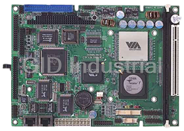
AAEON PCM-6892E
Description
VIA C3 / Eden Low Power Processors, All-in-One FC 370 Pentium III/Celeron Single Board with LCD, AC97 Audio, Dual 10/100Base-Tx Ethernet Interfaces, & 4 COMs
Part Number
PCM-6892E
Price
Request Quote
Manufacturer
AAEON
Lead Time
Request Quote
Category
Single Board Computers
Specifications
Ethernet Chipset
Realtek RTL8139C
Video Chipset
VIA VT8606
Form Factor
EBX
Datasheet

Extracted Text
User’s Manual
PCM-6892E
All-in-One FC 370 Pentium III/Celeron Single Board with LCD,
AC97 Audio, Dual 10/100Base-Tx Ethernet Interfaces, & 4 COMs
st
1 Ed. - 20 March 2001
PCM-6892E
FCC STATEMENT
THIS DEVICE COMPLIES WITH PART 15 FCC RULES. OPERATION IS SUBJECT TO
THE FOLLOWING TWO CONDITIONS:
(1) THIS DEVICE MAY NOT CAUSE HARMFUL INTERFERENCE.
(2) THIS DEVICE MUST ACCEPT ANY INTERFERENCE
RECEIVED INCLUDING INTERFERENCE THAT MAY CAUSE UNDESIRED
OPERATION.
THIS EQUIPMENT HAS BEEN TESTED AND FOUND TO COMPLY WITH THE LIMITS
FOR A CLASS "A" DIGITAL DEVICE, PURSUANT TO PART 15 OF THE FCC RULES.
THESE LIMITS ARE DESIGNED TO PROVIDE REASONABLE PROTECTION
AGAINTST HARMFUL INTERFERENCE WHEN THE EQUIPMENT IS OPERATED IN A
COMMERCIAL ENVIRONMENT. THIS EQUIPMENT GENERATES, USES, AND CAN
RADIATE RADIO FREQUENCY ENERGY AND, IF NOT INSTATLLED AND USED IN
ACCORDANCE WITH THE INSTRUCTION MANUAL, MAY CAUSE HARMFUL
INTERFERENCE TO RADIO COMMUNICATIONS.
OPERATION OF THIS EQUIPMENT IN A RESIDENTIAL AREA IS LIKELY TO CAUSE
HARMFUL INTERFERENCE IN WHICH CASE THE USER WILL BE REQUIRED TO
CORRECT THE INTERFERENCE AT HIS OWN EXPENSE.
User’s Manual
Copyright Notice
Copyright 2001, ALL RIGHTS RESERVED.
No part of this document may be reproduced, copied, translated, or transmitted in any
form or by any means, electronic or mechanical, for any purpose, without the prior written
permission of the original manufacturer.
Trademark Acknowledgement
Brand and product names are trademarks or registered trademarks of their respective
owners.
Disclaimer
EMAC, Inc. reserves the right to make changes, without notice, to any
product, including circuits and/or software described or contained in this manual in order
to improve design and/or performance. EMAC assumes no responsibility or
liability for the use of the described product(s), conveys no license or title under any patent,
copyright, or mask work rights to these products, and makes no representations or
warranties that these products are free from patent, copyright, or mask work right
infringement, unless otherwise specified. Applications that are described in this manual
are for illustration purposes only. EMAC, Inc. makes no representation or
warranty that such application will be suitable for the specified use without further testing
or modification.
Life Support Policy
EMAC, Inc. PRODUCTS ARE NOT FOR USE AS CRITICAL COMPONENTS IN
LIFE SUPPORT DEVICES OR SYSTEMS WITHOUT THE PRIOR WRITTEN APPROVAL
OF EMAC, Inc.
As used herein:
1. Life support devices or systems are devices or systems which, (a) are intended for
surgical implant into body, or (b) support or sustain life and whose failure to perform,
when properly used in accordance with instructions for use provided in the labelling,
can be reasonably expected to result in significant injury to the user.
2. A critical component is any component of a life support device or system whose failure
to perform can be reasonably expected to cause the failure of the life support device or
system, or to affect its safety or effectiveness.
PCM-6892E
A Message to the Customer
EMAC Customer Services
Each and every EMAC product is built to the most exacting specifications to ensure
reliable performance in the harsh and demanding conditions typical of industrial
environments. Whether your new EMAC device is destined for the laboratory or the
factory floor, you can be assured that your product will provide the reliability and ease of
operation for which the name EMAC has come to be known.
Your satisfaction is our primary concern. Here is a guide to EMAC’s customer services.
To ensure you get the full benefit of our services, please follow the instructions below
carefully.
Technical Support
We want you to get the maximum performance from your products. So if you run into
technical difficulties, we are here to help. For the most frequently asked questions, you
can easily find answers in your product documentation. These answers are normally a lot
more detailed than the ones we can give over the phone. So please consult this manual
first.
To receive the latest version of the user manual, please visit our Web site at:
http://www.emacinc.com/
If you still cannot find the answer, gather all the information or questions that apply to your
problem, and with the product close at hand, call your dealer. Our dealers are well trained
and ready to give you the support you need to get the most from your EMAC product. In
fact, most problems reported are minor and are able to be easily solved over the phone.
In addition, free technical support is available from EMAC engineers every business day.
We are always ready to give advice on application requirements or specific information on
the installation and operation of any of our products. Please do not hesitate to call or e-
mail us.
EMAC, Inc.
2390 EMAC Way
Carbondale, IL 62901
U.S.A.
Tel : (618) 529-4525
Fax : (618) 457-0110
http://www.emacinc.com
E-mail: info@emacinc.com
User’s Manual
Product Warranty
EMAC warrants to you, the original purchaser, that each of its products will be free from
defects in materials and workmanship for two years from the date of purchase.
This warranty does not apply to any products which have been repaired or altered by
persons other than repair personnel authorized by EMAC, or which have been subject to
misuse, abuse, accident or improper installation. EMAC assumes no liability under the
terms of this warranty as a consequence of such events. Because of EMAC’s high
quality-control standards and rigorous testing, most of our customers never need to use
our repair service. If an EMAC product is defective, it will be repaired or replaced at no
charge during the warranty period. For out-of-warranty repairs, you will be billed according
to the cost of replacement materials, service time, and freight. Please consult your dealer
for more details. If you think you have a defective product, follow these steps:
1. Collect all the information about the problem encountered. (For example, CPU type
and speed, EMAC product model name, hardware & BIOS revision number, other
hardware and software used, etc.) Note anything abnormal and list any on-screen
messages you get when the problem occurs.
2. Call your dealer and describe the problem. Please have your manual, product, and any
helpful information readily available.
3. If your product is diagnosed as defective, obtain an RMA (return material authorization)
number from your dealer. This allows us to process your good return more quickly.
4. Carefully pack the defective product, a complete Repair and Replacement Order Card
and a photocopy proof of purchase date (such as your sales receipt) in a shippable
container. A product returned without proof of the purchase date is not eligible for
warranty service.
5. Write the RMA number visibly on the outside of the package and ship it prepaid to your
dealer.
PCM-6892E
Packing List
Before you begin installing your single board, please make sure that the following
materials have been shipped:
� 1 PCM-6892E All-in-One FC370 Celeron / Pentium III Computing Module
� 1 Quick Installation Guide
� 1 CD-ROM contains the followings:
— User’s Manual (this manual in PDF file)
— Ethernet driver and utilities
— VGA drivers and utilities
— Audio drivers and utilities
— Latest BIOS (as of the CD-ROM was made)
If any of these items are missing or damaged, please contact your distributor or sales
representative immediately.
User’s Manual
1. MANUAL OBJECTIVES........................................................................................................1
2. INTRODUCTION...................................................................................................................2
2.1 System Overview..............................................................................................................2
2.2 System Specifications .....................................................................................................3
2.3 Architecture Overview .....................................................................................................6
2.3.1 VIA VT82C694X ..........................................................................................................7
2.3.2 DRAM Interface ...........................................................................................................7
2.3.3 AGP Interface ..............................................................................................................7
2.3.4 PCI Interface................................................................................................................8
2.3.5 VIA VT82C686A ..........................................................................................................8
2.3.6 IDE Interface (Bus Master Capability and Synchronous DMA Mode) ...........................9
2.3.7 USB .............................................................................................................................9
2.3.8 SMI Lynx3DM SM721 VGA Controller..........................................................................9
2.3.9 Panel Interface...........................................................................................................11
2.3.10 Zoom Video Port........................................................................................................11
2.3.11 TV Encoder................................................................................................................12
2.3.12 Ethernet .....................................................................................................................13
2.3.13 Compact Flash Interface............................................................................................14
2.3.14 Panel Link Interface (Optional)...................................................................................14
3. HARDWARE CONFIGURATION.........................................................................................15
3.1 Installation Procedure....................................................................................................15
3.2 Safety Precautions .........................................................................................................15
3.2.1 Warning! ....................................................................................................................15
3.2.2 Caution! .....................................................................................................................15
3.3 Socket 370 Processor ....................................................................................................16
3.3.1 Installing Pentium III / Celeron CPU...........................................................................16
3.3.2 Removing CPU ..........................................................................................................16
3.4 Main Memory ..................................................................................................................16
3.5 Jumper & Connector......................................................................................................17
3.5.1 Jumper & Connector Layout ......................................................................................17
3.5.2 Jumper & Connector List ...........................................................................................18
Connectors...............................................................................................................................19
3.6 Setting Jumpers .............................................................................................................20
3.7 Clear CMOS (J3) .............................................................................................................20
3.8 COM3 / 4 Pin 9 Signal Select (J5 / J4)...........................................................................21
3.9 COM2 RS-232/422/485 Select (J6, J7) ...........................................................................22
PCM-6892E
3.10 Connector Definitions....................................................................................................23
3.10.1 Power Connector 1 (PWR1) ......................................................................................23
3.10.2 LCD Inverter Connector (J1)......................................................................................23
3.10.3 Signal Configuration – LCD Inverter Connector (J1) ..................................................23
3.10.4 Auxiliary Power Connector (J2)..................................................................................24
3.10.5 Ethernet 1 / 2 LED Connector (CN1)..........................................................................24
3.10.6 Signal Description – Ethernet 1 / 2 LED Connector (CN1) .........................................24
3.10.7 Zoom Video Port Connector (CN2) ............................................................................25
3.10.8 Signal Description – Zoom Video Port Connector (CN2)............................................25
3.10.9 Video Port Interface I/O Compliance..........................................................................26
3.10.10 Primary LCD Panel Connector (CN3) ........................................................................27
3.10.11 Secondary LCD Panel Connector (CN4)....................................................................28
3.10.12 Signal Description – Primary & Secondary LCD Panel Connector (CN3, CN4)..........29
3.10.13 Signal Configuration – DSTN & TFT Panel Displays..................................................30
3.10.14 CD-ROM Audio Input Connector (CN5) .....................................................................32
3.10.15 Signal Configuration – CD-ROM Input Connector (CN5) ...........................................32
3.10.16 Audio / TV Output Connector (CN6) ..........................................................................33
3.10.17 Signal Description – Audio / TV Output Connector (CN6) ..........................................33
3.10.18 Pin Header Serial Port 1 / 2 / 3 / 4 Connector in RS-232 Mode (CN7) .......................34
3.10.19 Serial Port 1 / 2 / 3 / 4 with External DB9 Connector..................................................34
3.10.20 Signal Description – Serial Port 1 / 2 / 3 / 4 Connector in RS-232 Mode (CN7) .........35
3.10.21 Pin Header Serial Port 2 Connector (CN7 / Pin 11~20) in RS-422 Mode ...................35
3.10.22 Signal Description – Serial Port 2 in RS-422 Mode ....................................................35
3.10.23 Pin Header Serial Port 2 Connector (CN7 / Pin 11~20) in RS-485 Mode ...................36
3.10.24 Signal Description – Serial Port 2 in RS-485 Mode ....................................................36
3.10.25 PC/104 Connector (CN8, CN9)..................................................................................37
3.10.26 Signal Description – PC/104 Connector (CN8, CN9) .................................................38
3.10.27 Keyboard and PS/2 Mouse Connector (CN10)...........................................................41
3.10.28 Signal Description – Keyboard / Mouse Connector (CN10)........................................41
3.10.29 IDE Device Connector (CN11) ...................................................................................42
3.10.30 Signal Description – IDE Device Connector (CN11)...................................................43
3.10.31 CPU Fan Connector (CN12) ......................................................................................44
3.10.32 Signal Description – CPU Fan Connector (CN12)......................................................44
3.10.33 Front Panel Connector (CN13) ..................................................................................44
3.10.34 Signal Description – Front Panel Connector (CN13) ..................................................44
3.10.35 Floppy Disk Connector (FLP1)...................................................................................45
3.10.36 Signal Description – Floppy Disk Connector (FLP1) ..................................................46
3.10.37 IrDA Connector (IR1) .................................................................................................46
3.10.38 Signal Configuration – IR Connector (IR1).................................................................46
3.10.39 10/100 BASE-Tx Ethernet Connector (LAN1, LAN2) .................................................47
3.10.40 Signal Description – 10/100Base-Tx Ethernet Connector (LAN1, LAN2) ...................47
3.10.41 Panel Link Connector (PL1, Optional)........................................................................47
3.10.42 Signal Description – Panel Link Connector (PL1, Optional) .......................................48
3.10.43 Parallel Port Connector (PNT1) .................................................................................49
3.10.44 DB25 Parallel Port Connector ....................................................................................50
3.10.45 Signal Description – Parallel Port (PNT1) ..................................................................51
3.10.46 USB Connector (USB1) .............................................................................................51
3.10.47 Signal Description – USB Connector (USB1).............................................................51
3.10.48 CRT Connector (VGA1) .............................................................................................52
3.10.49 Signal Description – CRT Connector (VGA1).............................................................52
3.10.50 LCD Backlight Brightness Adjustment Connector (VR1)............................................52
3.10.51 STN LCD Contrast Adjustment Connector (VR2).......................................................53
User’s Manual
4. AWARD BIOS SETUP ........................................................................................................54
4.1 Starting Setup.................................................................................................................54
4.2 Using Setup ....................................................................................................................55
4.2.1 Navigating Through The Menu Bar ............................................................................55
4.2.2 To Display a Sub Menu..............................................................................................55
4.3 Getting Help....................................................................................................................56
4.4 In Case of Problems.......................................................................................................56
4.5 Main Menu.......................................................................................................................56
4.5.1 Setup Items ...............................................................................................................57
4.5.2 Standard CMOS Setup ..............................................................................................58
4.5.3 Advanced BIOS Features ..........................................................................................61
4.5.4 Advanced Chipset Features.......................................................................................64
4.5.5 Integrated Peripherals................................................................................................67
4.5.6 Power Management Setup.........................................................................................70
4.5.7 PnP/PCI Configuration Setup.....................................................................................74
4.5.8 Frequency / Voltage Control ......................................................................................77
4.5.9 Defaults Menu............................................................................................................78
4.5.10 Supervisor / User Password Setting...........................................................................79
4.5.11 Exit Selecting .............................................................................................................80
5. DRIVER INSTALLATION ....................................................................................................82
5.1 Driver Installation for Ethernet Adapter........................................................................82
5.1.1 Windows 9x ...............................................................................................................82
5.1.2 Windows NT 4.0 Ethernet Installation ........................................................................87
5.2 Driver Installation for Display Adapter .........................................................................93
5.2.1 Windows 9x ...............................................................................................................93
5.2.2 Windows NT 4.0 Display Installation..........................................................................98
5.3 Driver Installation for Audio Adapter ..........................................................................102
5.3.1 Windows 9x .............................................................................................................102
5.3.2 Windows NT 4.0 Audio Installation ..........................................................................107
6. MEASUREMENT DRAWING ............................................................................................112
PCM-6892E
APPENDIX A: BIOS REVISIONS ...............................................................................................113
APPENDIX B: SYSTEM RESOURCES ......................................................................................114
Memory Map.........................................................................................................................114
I/O – Map..............................................................................................................................115
Interrupt Usage.....................................................................................................................117
DMA-channel Usage.............................................................................................................118
APPENDIX C: PROGRAMMING THE WATCHDOG TIMER ......................................................119
Introduction...........................................................................................................................119
Configure Register................................................................................................................119
Programming Watchdog Timer.............................................................................................120
Demo Program 1 (Micro-Assembly Language) .....................................................................121
Demo Program 2 (C Language)............................................................................................124
APPENDIX D: AWARD BIOS POST MESSAGES......................................................................126
POST Beep .............................................................................................................................126
Error Messages......................................................................................................................126
CMOS Battery Has Failed.....................................................................................................126
CMOS Checksum Error ........................................................................................................126
Disk Boot Failure, Insert System Disk and Press Enter ........................................................126
Diskette Drives or Types Mismatch Error – Run Setup .........................................................126
Display Switch Is Set Incorrectly...........................................................................................126
Display Type Has Changed Since Last Boot ........................................................................127
Error Encountered Initializing Hard Drive..............................................................................127
Error Initializing Hard Disk Controller ....................................................................................127
Floppy Disk Cntrlr Error or No Cntrlr Present........................................................................127
Keyboard Error or No Keyboard Present ..............................................................................127
Memory Address Error at......................................................................................................127
Memory Parity Error at..........................................................................................................127
Memory Size Has Changed Since Last Boot ........................................................................127
Memory Verify Error at..........................................................................................................128
Offending Address Not Found ..............................................................................................128
Offending Segment:..............................................................................................................128
Press A Key to Reboot .........................................................................................................128
Press F1 to Disable NMI, F2 to Reboot ................................................................................128
RAM Parity Error – Checking for Segment... ........................................................................128
System Halted, (CTRL-ALT-DEL) to Reboot.........................................................................128
Floppy Disk(s) Fail (80) → Unable to Reset Floppy Subsystem............................................128
Floppy Disk(s) Fail (40) → Floppy Type Dismatch ................................................................128
Hard Disk(s) Fail (80) → HDD Reset Failed..........................................................................128
Hard Disk(s) Fail (40) → HDD Controller Diagnostics Failed ................................................128
Hard Disk(s) Fail (20) → HDD Initialization Error ..................................................................128
Hard Disk(s) Fail (10) → Unable to Recalibrate Fixed Disk...................................................128
Hard Disk(s) Fail (08) → Sector Verify Failed .......................................................................129
Keyboard Is Locked Out - Unlock The Key...........................................................................129
Keyboard Error or No Keyboard Present ..............................................................................129
Manufacturing POST Loop ...................................................................................................129
BIOS ROM Checksum Error – System Halted......................................................................129
Memory Test Fail..................................................................................................................129
User’s Manual
APPENDIX E: AWARD BIOS POST CODES .............................................................................130
APPENDIX F: AUDIO / USB DAUGHTER BOARD USER’S GUIDE..........................................136
Jumper & Connector Layout.................................................................................................136
Jumper & Connector List ......................................................................................................136
Measurement Drawing...........................................................................................................137
PCM-6892E
Document Amendment History
Revision Date By Comment
st
1 Mar. 01. Philip Chang Initial Release
PCM-6892E
1. Manual Objectives
This manual describes in detail the EMAC, Inc. PCM-6892E Single Board
Computer.
We have tried to include as much information as possible but we have not duplicated
information that is provided in the standard IBM Technical References, unless it proved to
be necessary to aid in the understanding of this board.
We strongly recommend that you study this manual carefully before attempting to
interface with PCM-6892E or change the standard configurations. Whilst all the necessary
information is available in this manual we would recommend that unless you are confident,
you contact your supplier for guidance.
Please be aware that it is possible to create configurations within the CMOS RAM that
make booting impossible. If this should happen, clear the CMOS settings, (see the
description of the Jumper Settings for details).
If you have any suggestions or find any errors concerning this manual and want to inform
us of these, please contact our Customer Service department with the relevant details.
PCM-6892E User’s Manual 1
User’s Manual
2. Introduction
2.1 System Overview
The PCM-6892E is a compact 5.25” CD-ROM size Single Board Computer that equips
with VIA Apollo Pro 133A AGPset, SMI AGP 2X Lynx3DM 2D/3D Graphics and
Multimedia Accelerator w/ Embedded 4MB SGRAM, Dual LCD interfaces, NTSC/PAL TV
output, AC97 Audio, and dual PCI-bus Ethernet interfaces.
Targeting on the rapid growing networking and multimedia embedded markets, the PCM-
6892E comes designed with dual PCI-bus Intel 82559ER 10/100Base-Tx chips and dual
LCD interfaces. This make it a perfect solution for not only popular Networking Devices
like Firewall, Gateway, Router, Thin Server, and E-Box but also Retail / Financial
Transaction Terminals, and high-end multimedia POS / KIOSK Terminals.
In addition, the on board 24-bit Panel Link interface, Zoom Video port, and NTSC/PAL TV
output interface make the PCM-6892E also ideal for demanding high-end Entertainment
Devices that require high integration multimedia Single Board Computer.
Other impressive features include PC133 FSB, Ultra DMA66 IDE, a Compact Flash socket
for type I/II Compact Flash storage card, four serial ports, one parallel port, one 168-pin
DIMM socket allowing for up to 256MB of SDRAM to be installed, and a PCI slot for future
expansion.
2 PCM-6892E User’s Manual
PCM-6892E
2.2 System Specifications
General Functions
‧‧‧‧CPU: Intel FC-370 Pentium III/Celeron (with system bus frequencies of 66/100/133MHz)
‧‧‧‧
CPU socket: Intel Socket 370
‧‧‧‧BIOS: Award 256KB Flash BIOS
‧‧‧‧Chipset: VIA Apollo Pro 133A, VT82C694X
‧‧‧‧
I/O Chipset: VT82C686A / Winbond W83977EF-AW
‧‧‧‧Memory: Onboard one 168-pin DIMM socket supports up to 256 Mbytes SDRAM
‧‧‧‧Enhanced IDE: Supports two IDE devices. Supports Ultra DMA/66 mode with data
transfer rate up to 66MB/sec. (20 x 2 header onboard)
‧‧‧‧
FDD interface: Supports up to two floppy disk drives, 5.25" (360KB and 1.2MB) and/or
3.5" (720KB, 1.44MB and 2.88MB)
‧‧‧‧Parallel port: One bi-directional parallel port. Supports SPP, ECP, and EPP modes
‧‧‧‧
Serial port: Three RS-232 and one RS-232/422/485 serial port. Ports can be
configured as COM1, COM2, COM3, COM4, or disabled individually. (16C550
equivalent)
‧‧‧‧IR interface: Supports one IrDA Tx/Rx header
‧‧‧‧
KB/Mouse connector: 8-pin (4 x 2) connector supports PS/2 keyboard and mouse
‧‧‧‧USB connectors: One 5 x 2 header onboard supports dual USB ports
‧‧‧‧Watchdog Timer: Can generate a system reset, IRQ15 or NMI. Software selectable
time out interval (32 sec. ~ 254 min., 1 min./step)
‧‧‧‧
DMA: 7 DMA channels (8237 equivalent)
‧‧‧‧Interrupt: 15 interrupt levels (8259 equivalent)
‧‧‧‧Power management: Supports ATX power supply. Supports PC97, LAN wake up and
modem ring-in functions. I/O peripheral devices support power saving and
doze/standby/suspend modes. APM 1.2 compliant.
PCM-6892E User’s Manual 3
User’s Manual
Flat Panel/CRT Interface
‧‧
‧‧Chipset: SMI Lynx3DM SM721, high performance 128-bit GUI, 3D engine
‧‧‧‧Display memory: 4 MB of SGRAM frame buffer on Lynx3DM SM721G4. Optional 8 MB
SGRAM frame buffer on Lynx3DM SM721G8
‧‧
‧‧Display type: Simultaneously supports CRT and flat panel (EL, LCD and gas plasma)
displays
‧‧‧‧Interface: 2X AGP, Accelerator Graphics Ports 1.0 compliant
‧‧‧‧Display mode:
LCD panel supports up to 800 x 600 @ 24 bpp, 1024 x 768 @ 24 bpp
CRT displays support up to 800 x 600 @ 24 bpp, 1024 x 768 @ 24 bpp
‧‧‧‧
Video capture port: 40-pin YUV Direct Video Input Port onboard
‧‧‧‧TV output interface: Supports both RCA jack and S terminal
Panel Link (Optional)
‧‧‧‧Chipset: Sil 164 PanelLink Digital Transmitter
‧‧‧‧Scalable bandwidth: Ranging from 25 ~ 112 MHz (VGA ~ SXGA); 24/48-bit one/two
pixel per clock
Audio Interface
‧‧‧‧Chipset: VT82C686A
‧‧‧‧Audio controller: AC97 ver. 2.0 compliant interface, Multi-stream Direct Sound and
Direct Sound 3D acceleration
‧‧Audio interface: Microphone in, Line in, CD audio in, line out, Speaker L, Speaker R
‧‧
Ethernet Interface
‧‧‧‧Chipset: Dual Intel 82559ER PCI-bus Ethernet controllers onboard
‧‧Ethernet interface: PCI 100/10 Mbps, IEEE 802.3U compatible
‧‧
‧‧Remote Boot-ROM: For diskless system
‧‧
SSD Interface
One CF socket supports Type I/II Compact Flash Card
4 PCM-6892E User’s Manual
PCM-6892E
Expansion Interface
‧‧
‧‧PC/104 connector: One 16-bit 104-pin connector onboard
‧‧‧‧PCI slot: One 32-bit PCI slot onboard
Mechanical and Environmental
‧‧‧‧
Power supply voltage: ATX type, +5V and +12V
‧‧‧‧Typical power requirement: 5V @ 5.2A, 12V @ 80mA w/ PIII 800MHz & 128MB
SDRAM
‧‧
‧‧Operating temperature: 32 to 140°F (0 to 60°C)
‧‧‧‧
Board size: 8”(L) x 5.75”(W) (203mm x 146mm)
‧‧‧‧Weight: 0.5 Kg
PCM-6892E User’s Manual 5
User’s Manual
2.3 Architecture Overview
The following block diagram shows the architecture and main components of PCM-6892E.
The two key components on board are the VIA VT82C694X North Bridge and VT82C686A
super South Bridge. These two devices provide the ISA and PCI bus to which all the major
components are attached.
The following sections provide detailed information about the functions provided onboard.
6 PCM-6892E User’s Manual
PCM-6892E
2.3.1 VIA VT82C694X
The VIA VT82C694X along with the VT82C686A companion chip provide the basic
functionality and buses of the system:
� High Performance CPU interface.
� Full Featured Accelerated Graphics Port (AGP) controller.
� Advanced High-Performance DRAM controller. PC133 compliant SDRAM must be
used if 133MHz FSB CPU is to be used.
� Concurrent PCI Bus controller.
� PCI to ISA Bridge provided by VT82C686A super south bridge.
� Universal Serial Bus controller integrated in the VT82C686A.
� UltraDMA-33 / 66 Master Mode PCI EIDE controller. Two connectors are provided: A
40 pin pitch 2.54mm standard IDE interface on the primary controller and a Compact
Flash connector on the secondary controller.
� SoundBlaster Pro hardware and Direct Sound ready AC97 Digital Audio controller.
2.3.2 DRAM Interface
The VT82C694X supports eight banks of DRAMs up to 1.5GB. The DRAM controller
supports standard Fast Page Mode (FPM) DRAM, EDO-DRAM, Synchronous DRAM
(SDRAM) and Virtual Channel SDRAM (VC SDRAM), in a flexible mix / match manner.
The Synchronous DRAM interface allows zero wait state bursting between the DRAM and
the data buffers at 66/100/133 MHz. The eight banks of DRAM can be composed of an
arbitrary mixture of 1M / 2M / 4M / 8M / 16M / 32MxN DRAMs. The DRAM controller also
supports optional ECC (single-bit error correction and multi-bit detection) or EC (error
checking) capability separately selectable on a bank-by-bank basis. The DRAM controller
can run at either the host CPU bus frequency (66 /100 /133MHz) or at the AGP bus
frequency (66 MHz) with built-in PLL timing control.
2.3.3 AGP Interface
The VT82C694X system controller also supports full AGP v2.0 capability for maximum
bus utilization including 2x and 4x mode transfers, SBA (SideBand Addressing),
Flush/Fence commands, and pipelined grants. An eight level request queue plus a four
level post-write request queue with thirty-two and sixteen quadwords of read and write
data FIFO's respectively are included for deep pipelined and split AGP transactions. A
single-level GART TLB with 16 full associative entries and flexible CPU / AGP / PCI
remapping control is also provided for operation under protected mode operating
environments. Both Windows-95 VXD and Windows-98 / NT5 miniport drivers are
supported for interoperability with major AGP-based 3D and DVD-capable multimedia
accelerators.
PCM-6892E User’s Manual 7
User’s Manual
2.3.4 PCI Interface
The VT82C694X supports two 32-bit 3.3 / 5V system buses (one AGP and one PCI) that
are synchronous / pseudo-synchronous to the CPU bus. The chip also contains a built-in
bus-to-bus bridge to allow simultaneous concurrent operations on each bus. Five levels
(doublewords) of post write buffers are included to allow for concurrent CPU and PCI
operation. For PCI master operation, forty-eight levels (doublewords) of post write buffers
and sixteen levels (doublewords) of prefetch buffers are included for concurrent PCI bus
and DRAM/cache accesses. The chip also supports enhanced PCI bus commands such
as Memory-Read-Line, Memory-Read-Multiple and Memory-Write-Invalid commands to
minimize snoop overhead. In addition, advanced features are supported such as snoop
ahead, snoop filtering, L1 write-back forward to PCI master, and L1 write-back merged
with PCI post write buffers to minimize PCI master read latency and DRAM utilization.
Delay transaction and read caching mechanisms are also implemented for further
improvement of overall system performance.
2.3.5 VIA VT82C686A
The VT82C686A PSIPC (PCI Super-I/O Integrated Peripheral Controller) is a high
integration, high performance, power-efficient, and high compatibility device that supports
Intel and non-Intel based processor to PCI bus bridge functionality to make a complete
Microsoft PC99-compliant PCI/ISA system. In addition to complete ISA extension bus
functionality, the VT82C686A includes standard intelligent peripheral controllers:
� Two 16550-compatible serial I/O ports with infrared communications port option
on the second port.
� LPT support for SPP, EPP and ECP modes.
� Standard floppy disk drive interface.
� Keyboard controller with PS2 mouse support.
� Real Time Clock with 256 byte extended CMOS. In addition to the standard ISA
RTC functionality, the integrated RTC also includes the date alarm, century field,
and other enhancements for compatibility with the ACPI standard.
� Notebook-class power management functionality compliant with ACPI and legacy
APM requirements. Multiple sleep states (power-on suspend, suspend-to-DRAM,
and suspend-to-Disk) are supported with hardware automatic wake-up.
Additional functionality includes event monitoring, CPU clock throttling and stop
(Intel processor protocol), PCI bus clock stop control, modular power, clock and
leakage control, hardware-based and software-based event handling, general
purpose I/O, chip select and external SMI.
� Full System Management Bus (SMBus) interface.
8 PCM-6892E User’s Manual
PCM-6892E
� Integrated PCI-mastering dual full-duplex direct-sound AC97-link-compatible
sound system. Hardware SoundBlaster-Pro and hardware-assisted FM blocks
are included for Windows DOS box and real-mode DOS compatibility. Loopback
capability is also implemented for directing mixed audio streams into USB and
1394 speakers for high quality digital audio.
� Plug and Play controller that allows complete steerability of all PCI interrupts and
internal interrupts / DMA channels to any interrupt channel. One additional
steerable interrupt channel is provided to allow plug and play and
reconfigurability of on-board peripherals for Windows family compliance.
� Internal I/O APIC (Advanced Programmable Interrupt Controller).
2.3.6 IDE Interface (Bus Master Capability and Synchronous DMA Mode)
Master mode enhanced IDE controller with dual channel DMA engine and interlaced dual
channel commands. Dedicated FIFO coupled with scatter and gather master mode
operation allows high performance transfers between PCI and IDE devices. In addition to
standard PIO and DMA mode operation, the VT82C686A also supports the UltraDMA-33
standard to allow reliable data transfer rates up to 33MB/sec throughput. The VT82C686A
also supports the UltraDMA-66 standard. The IDE controller is SFF-8038i v1.0 and
Microsoft Windows-family compliant.
Access to these controllers is provided by one standard IDC 40-pin connector and one
Compact Flash type II connector.
2.3.7 USB
Universal Serial Bus controller that is USB v1.1 and Universal HCI v1.1 compliant. The
VT82C686A includes the root hub with four function ports with integrated physical layer
transceivers. The USB controller allows hot plug and play and isochronous peripherals to
be inserted into the system with universal driver support. The controller also implements
legacy keyboard and mouse support so that legacy software can run transparently in a
non-USB-aware operating system environment.
2.3.8 SMI Lynx3DM SM721 VGA Controller
The Lynx3DM consists of a logic block, which interfaces to a 4MB or 8MB block of
integrated memory. The integrated memory supports single clock cycle transfers up to
100MHz. Peak memory bandwidth for the integrated 128-bit memory bus is over 1.6GB/s.
The logic within the Lynx3DM consists of 11 functional blocks: PCI Interface, Host
Interface (HIF), Memory Controller, Drawing Engine, Power Down Control Unit, Video
Processor, Video Capture Module, LCD Backend Controller, VGA Core, PLL Module, and
RAMDAC. A summary of each of the functional blocks, along with important features
follows:
� AGP 2X sideband support
� PCI 2.1 compliant
� 33 MHz PCI Master/Slave interface
� Dual aperture feature for concurrent VGA and video/drawing engine access
PCM-6892E User’s Manual 9
User’s Manual
� Independent memory interface control
� Up to 128-bit memory interface
� Over 1.6GB/s memory bandwidth
� 100MHz single clock/cycle engine
� Designed to accelerate DirectDraw and Direct3D
� IEEE Floating Point Setup Engine
� Complete 3D Rendering Engine set:
- Bi-linear and tri-linear filtering
- Mip Mapping
- Vertex and global fog
- Source and destination alpha blend
- Specular highlights
- Edge anti-aliasing
- Z-buffering
- Gouraud shading
- Mirrored textures
-Texture decompression
� Offloads motion compensation portion of MPEG-2 decode process from CPU
� Separate bus master control for motion compensation command and IDCT data
� Sub-picture support
- 2-bit/pixel format
- 8-bit/pixel format
� NTSC/PAL interlace mode digital video encoder
� Composite Video and S-Video digital output
� CCIR 601, Square pixel and 4Fsc (NTSC only) resolution RGB input
� Interlace mode operation
� 2x over-sampling data output to simplify external analog filtering
� Macrovision function (version 7.1.21)
� Closed captioning function
� Dynamic Power Management
� Virtual Refresh
� Standby and Suspend model support
� ACPI, DPMS, APM compliant
� Multiple video windows in HW
� Independent video sources on different displays
� Bi-linear scaling
� Flicker filter and underscan for TV display
� Support for Zoom Video Port interface
� Crop, filter, shrink support
� TFT and DSTN support up to SXGA
� Timing generation for Virtual Refresh
� Popup icon location flexible
� Transparency color support
� 100% IBM VGA compatible
� Separate PLL for LCD panel timing
� 200MHz speed provides resolution support to 1600x1200.
10 PCM-6892E User’s Manual
PCM-6892E
2.3.9 Panel Interface
Alternative displays to the standard CRT monitor are digital flat panel interfaces in which
the color of each pixel is digitally encoded. The panel data may be transferred in parallel
where the color of each pixel is transferred over a number of signal lines at rates up to
80MHz.
Lynx3DM supports both color dual scan STN (passive) and color TFT (active) panel
interface. It can also support color TFT panel with RGB analog interface. For color DSTN
panel, Lynx3DM can support 16-bit and 24-bit interfaces up to 1600x1200 resolution. For
color TFT panel, Lynx3DM can support single pixel per clock of 9-bit, 12-bit, 18-bit, 24-bit,
or double-pixel per clock of 24-bit, 36-bit interfaces up to 1280x1024 resolution.
Lynx3DM supports two separate digital LCDs. Both LCDs need to be TFT interface. FP1
has to be only 18-bit TFT interface and FP2 has to be 24-bit TFT interface. DSTN panel
cannot be supported under dual digital LCD mode. Dual Digital LCD mode is supported
through the Virtual Refresh architecture. FP1 and FP2 must be in Virtual Refresh mode.
FP1 clocks the data based on VRCLK (Virtual Refresh Clock); whereas FP2 clocks the
data based on FIFOCLK (based on Video Clock).
The parallel interface is only suitable for short distance (less than 50 cm) and is typically
implemented by using of ribbon cables. One should be careful in the EMC design of the
box and cabling when this interface is used.
It should also be noted that the signal level of this interface is 3.3V, but does comply with
the TTL signal levels. Some or most older displays require a 5V signal level.
2.3.10 Zoom Video Port
Lynx3DM's Zoom Video Port (ZV Port) is designed to interface with video solutions
implemented as PCMCIA (or PC CardBus) cards: examples are NTSC/PAL decoders,
MPEG-2 decoders, and JPEG Codecs. The ZV Port can also directly interface with an
NTSC/PAL decoder, such as Philips 7111 or BT819.
Incoming video data from the ZV Port interface can be YUV or RGB format. The data can
be interlaced or non-interlaced. The ZV Port can be configured for output if the video
capture function is disabled. 18-bit graphics and video data in RGB format can be sent out
when the ZV Port is configured for output mode. The ZV Port may also be configured as a
test port. Up to 20 signals from each of the logic blocks within Lynx3DM can be brought
out to an internal test bus (TD Bus) connected to the ZV Port. System designers or silicon
validation engineers can access these signals by setting the TEST0, TEST1, USR0, USR1,
and USR2 pins. This approach can bring out a total of 180 internal signals to the primary
I/O pins. The test port capability can be used to enhance fault coverage, as well as
reduces silicon validation or debugging time.
The Video Capture Unit captures incoming video data from the ZV Port and then stores
the data into the frame buffer.
PCM-6892E User’s Manual 11
User’s Manual
The Video Capture Unit support several features to maintain display quality, and balance
the capture rate:
� 2-tap, 3-tap, and 4-tap horizontal filtering
� 2 to 1 and 4 to 1 reduction for horizontal and vertical frame size
� YUV 4:2:2, YUV 4:2:2 with byte swap, RGB 5:5:5, and RGB 5:6:5
� Multiple frame skipping methods
� Interlaced data and non-interlaced data capture
� Single buffer and double buffer capture
� Cropping
Lynx3DM uses the Video Processor block to display the captured data on the LCD, TV, or
CRT display. The captured data can be displayed through Video Window I or Video
Window II. The stretching, color interpolation, YUV-to-RGB conversion, and color key
functions are performed in the Video Processor. Lynx3DM's Video Processor can
simultaneously process captured video data and perform CD-ROM playback on two
independent video windows.
Lynx3DM also supports real-time video capture to the hard drive or system memory
through PCI master mode or slave mode. In PCI bus master mode, Lynx3DM uses the
Drawing Engine's Host BLT and Host DMA functions to maximize performance.
2.3.11 TV Encoder
The TV Encoder is an NTSC/PAL Composite Video/S-video Encoder. It receives RGB
inputs and converts to digital video signals based on CCIR 624 format.
The input video signal of the TV Encoder is RGB 8-bit each. The sampling rate is
corresponding to CCIR 601, Square pixel and 4Fsc (NTSC only).
The output video signals of the TV Encoder are Composite video signal and S-video
signals of 10-bit each. These output signals are over-sampled by a double frequency clock
called CLKX2. This feature helps to simplify external analog filtering.
The TV Encoder video timing is controlled by vertical sync and the horizontal sync input
signals. The blank signal input is optional. If the blank signal input signal is pulled up,
internal blanking control will be performed.
Macrovision 7.01 and closed captioning functions are included.
Key features are summarized as the following:
� NTSC/PAL interlace mode digital video encoder
� Composite Video and S-Video digital output
� CCIR 601, Square pixel and 4Fsc (NTSC only) resolution RGB input
� Slave timing operation
� Interlace mode operation
� 2x over-sampling data output to simplify external analog filtering
� Selectable pedestal level OIRE/7.5IRE for NTSC
� Macrovision function (version 7.01)
� Closed captioning function
12 PCM-6892E User’s Manual
PCM-6892E
2.3.12 Ethernet
The Ethernet interfaces are based on two Intel 82559ER Ethernet controllers, which
support both 100Mbit as well as l0Mbit Base-T interface.
The Ethernet controllers are attached to the PCI bus and use PCI bus mastering for data
transfer. The CPU is thereby not loaded during the actual data transfer.
The 82559ER is part of Intel's second-generation family of fully integrated 10BASE-
T/100BASE-TX LAN solutions. The 82559ER consists of both the Media Access
Controller (MAC) and the physical layer (PHY) combined into a single component solution.
82559 family members build on the basic functionality of the 82558 and contain power
management enhancements.
The 82559ER is a 32-bit PCI controller that features enhanced scatter-gather bus
mastering capabilities, which enables the 82559ER to perform high-speed data transfers
over the PCI bus. The 82559ER bus master capabilities enable the component to process
high-level commands and perform multiple operations, thereby off-loading communication
tasks from the system CPU. Two large transmit and receive FIFOs of 3 Kbytes each help
prevent data underruns and overruns, allowing the 82559ER to transmit data with
minimum interframe spacing (IFS).
The 82559ER can operate in either full duplex or half duplex mode. In full duplex mode
the 82559ER adheres to the IEEE 802.3x Flow Control specification. Half duplex
performance is enhanced by a proprietary collision reduction mechanism.
The 82559ER includes a simple PHY interface to the wire transformer at rates of 10BASE-
T and 100BASE-TX, and Auto-Negotiation capability for speed, duplex, and flow control.
These features and others reduce cost, real estate, and design complexity.
The 82559ER also includes an interface to a serial (4-pin) EEPROM and a parallel
interface to a 128 Kbyte Flash memory. The EEPROM provides power-on initialization for
hardware and software configuration parameters
PCM-6892E User’s Manual 13
User’s Manual
2.3.13 Compact Flash Interface
A Compact Flash type II connector is connected to the secondary IDE controller. The
Compact Flash storage card is IDE compatible. It is an ideal replacement for standard IDE
hard drives. The solid-state design offers no seek errors even under extreme shock and
vibration conditions. The Compact Flash storage card is extremely small and highly
suitable for rugged environments, thus providing an excellent solution for mobile
applications with space limitations. It is fully compatible with all consumer applications
designed for data storage PC card, PDA, and Smart Cellular Phones, allowing simple use
for the end user. The Compact Flash storage card is O/S independent, thus offering an
optimal solution for embedded systems operating in non-standard computing
environments. The Compact Flash storage card is IDE compatible and offers various
capacities.
2.3.14 Panel Link Interface (Optional)
®
The SiI164 transmitter uses PanelLink Digital technology to support displays ranging
from VGA to UXGA resolutions (25 - 165Mpps) in a single link interface. The SiI164
transmitter has a highly flexible interface with either a 12-bit mode (½ pixel per clock edge)
or 24-bit mode 1-pixel/clock input for true color (16.7 million) support. In 24-bit mode, the
SiI164 supports single or dual edge clocking. In 12-bit mode, the SiI164 supports dual
edge single clocking or single edge dual clocking. The SiI164 can be programmed though
an I2C interface. The SiI164 support Receiver and Hot Plug Detection.
PanelLink Digital technology simplifies PC design by resolving many of the system level
issues associated with high-speed mixed signal design, providing the system designer
with a digital interface solution that is quicker to market and lower in cost.
14 PCM-6892E User’s Manual
PCM-6892E
3. Hardware Configuration
This chapter explains you the instructions of how to setup your system.
3.1 Installation Procedure
1. Turn off the power supply.
2. Insert the DIMM module (be careful with the orientation).
3. Insert all external cables for hard disk, floppy, keyboard, mouse, USB etc. except for flat
panel. A CRT monitor must be connected in order to change CMOS settings to support
flat panel.
4. Connect power supply to the board via the PWR1.
5. Turn on the power.
6. Enter the BIOS setup by pressing the delete key during boot up. Use the “LOAD BIOS
DEFAULTS” feature. The Integrated Peripheral Setup and the Standard CMOS Setup
Window must be entered and configured correctly to match the particular system
configuration.
7. If TFT panel display is to be utilised, make sure the panel voltage is correctly set
before connecting the display cable and turning on the power.
3.2 Safety Precautions
3.2.1 Warning!
Always completely disconnect the power cord from your chassis or power
cable from your board whenever you work with the hardware. Do not make
connections while the power is on. Sensitive electronic components can
be damaged by sudden power surges. Only experienced electronics
personnel should open the PC chassis.
3.2.2 Caution!
Always ground yourself to remove any static charge before touching the
board. Modern electronic devices are very sensitive to static electric
charges. As a safety precaution, use a grounding wrist strap at all times.
Place all electronic components in a static-dissipative surface or static-
shielded bag when they are not in the chassis.
PCM-6892E User’s Manual 15
User’s Manual
3.3 Socket 370 Processor
3.3.1 Installing Pentium III / Celeron CPU
� Lift the handling lever of CPU socket outwards and upwards to the other end.
� Align the processor pins with pinholes on the socket. Make sure that the notched
corner or dot mark (pin 1) of the CPU corresponds to the socket’s bevel end.
Then press the CPU gently until it fits into place. If this operation is not easy or
smooth, don’t do it forcibly. You need to check and realign the CPU pin uniformly.
� Push down the lever to lock processor chip into the socket.
� Follow the installation guide of cooling fan or heat sink to mount it on CPU
surface and lock it on the socket 370.
� Make sure to follow particular CPU speed and voltage type to adjust the jumper
settings properly.
3.3.2 Removing CPU
� Unlock the cooling fan first.
� Lift the lever of CPU socket outwards and upwards to the other end.
� Carefully lift up the existing CPU to remove it from the socket.
� Follow the steps of installing a CPU to change to another one or place handling
bar back to close the opened socket.
3.4 Main Memory
PCM-6892E provides a DIMM socket (168-pin Dual In-line Memory Module) to support
3.3V SDRAM. The maximum memory size is 256MB (registered type of SDRAM). If
133MHz FSB CPU is adopt, you have to use PC-133 compliant SDRAM. For system
compatibility and stability, please do not use memory module without brand.
Watch out the contact and lock integrity of memory module with socket, it will influence the
system’s reliability. Follow the normal procedure to install your SDRAM module into the
DIMM socket. Before locking the DIMM module, make sure that the memory module has
been completely inserted into the DIMM socket.
Note:
Please do not change any SDRAM parameter in BIOS setup to increase your
system’s performance without acquiring technical information in advance.
16 PCM-6892E User’s Manual
PCM-6892E
3.5 Jumper & Connector
3.5.1 Jumper & Connector Layout
PCM-6892E User’s Manual 17
User’s Manual
3.5.2 Jumper & Connector List
Connectors on the board are linked to external devices such as hard disk drives, keyboard,
mouse, or floppy drives. In addition, the board has a number of jumpers that allow you to
configure your system to suit your application.
The following tables list the function of each of the board's jumpers and connectors.
Jumpers
Label Function Note
J1 LCD inverter connector 5 x 1 wafer, pitch 2.0mm
J2 Power connector 3 x 1 wafer, pitch 2.54mm
J3 Clear CMOS 3 x 1 header, pitch 2.54mm
J4 COM4 pin 9 signal select 3 x 2 header, pitch 2.0mm
J5 COM3 pin 9 signal select 3 x 2 header, pitch 2.0mm
J6, J7 COM2 RS-232/422/485 select 3 x 2 header, pitch 2.0mm
4 x 3 header, pitch 2.0mm
(J7)
J8 Reserve for future use 3 x 3 header, pitch 2.0mm
18 PCM-6892E User’s Manual
PCM-6892E
Connectors
Label Function Note
CN1 Ethernet 1 / 2 LED connector 5 x 2 header, pitch 2.54mm
CN2 Zoom Video port connector Samtec CLM-120-02-L-D
CN3 Primary LCD panel connector HIROSE DF13-40DP-1.25V
CN4 Secondary LCD panel connector HIROSE DF13-40DP-1.25V
CN5 CD-ROM audio input connector 4 x 1 wafer, pitch 2.0mm
CN6 Audio / TV output connector 8 x 2 header, pitch 2.54mm
CN7 Serial port 1 / 2 / 3 / 4 connector 20 x 2 header, pitch 2.54mm
CN8, 9 PC/104 connector
CN10 Keyboard and PS/2 mouse connector 4 x 2 header, pitch 2.54mm
CN11 IDE device connector 20 x 2 header, pitch 2.54mm
CN12 CPU fan connector 3 x 1 wafer, pitch 2.54mm
CN13 Front panel connector 4 x 2 header, pitch 2.54mm
FLP1 Floppy connector 17 x 2 header, pitch 2.54mm
IR1 IrDA connector 3 x 2 header, pitch 2.0mm
LAN1 10/100Base-Tx Ethernet 1 connector RJ-45
LAN2 10/100Base-Tx Ethernet 2 connector RJ-45
PL1 Panel link connector (Optional) 8 x 2 header, pitch 2.54mm
PNT1 Printer port connector 13 x 2 header, pitch 2.54mm
PWR1 Power connector
SN1 Compact Flash connector
USB1 USB connector 5 x 2 header, pitch 2.0mm
VGA1 CRT connector 8 x 2 header, pitch 2.54mm
VR1 LCD Backlight brightness adjustment 3 x 1 header, pitch 2.54mm
connector
VR2 STN LCD contrast adjustment connector 3 x 1 header, pitch 2.54mm
DIM1 168-pin DIMM socket
PCM-6892E User’s Manual 19
User’s Manual
3.6 Setting Jumpers
You can configure your board to match the needs of your application by setting jumpers. A
jumper is the simplest kind of electric switch.
It consists of two metal pins and a small metal clip (often protected by a plastic cover) that
slides over the pins to connect them. To “close” a jumper you connect the pins with the
clip. To “open” a jumper you remove the clip. Sometimes a jumper will have three pins,
labeled 1, 2, and 3. In this case, you would connect either two pins.
The jumper settings are schematically depicted in this manual as follows:
A pair of needle-nose pliers may be helpful when working with jumpers.
If you have any doubts about the best hardware configuration for your application, contact
your local distributor or sales representative before you make any changes.
3.7 Clear CMOS (J3)
You can use J3 to clear the CMOS data if necessary. To reset the CMOS data, set J3 to
2-3 closed for just a few seconds, and then move the jumper back to 1-2 closed.
Clear CMOS (J3)
Protect* Clear CMOS
1 2 3
1 2 3
J3
* default
20 PCM-6892E User’s Manual
PCM-6892E
3.8 COM3 / 4 Pin 9 Signal Select (J5 / J4)
The PCM-6892E COM3 / 4 pin 9 signal can be selected as +12V, +5V, or Ring by setting
J5 / J4.
COM3 Pin 9 Signal Select (J5)
+12V +5V Ring*
1 3 5 1 3 5 1 3 5
J5
2 4 6 2 4 6 2 4 6
* default
COM4 Pin 9 Signal Select (J4)
+12V +5V Ring*
1 3 5 1 3 5 1 3 5
J4
2 4 6 2 4 6 2 4 6
* default
PCM-6892E User’s Manual 21
User’s Manual
3.9 COM2 RS-232/422/485 Select (J6, J7)
The PCM-6892E COM2 serial port can be selected as RS-232, RS-422, or RS-485 by
setting J6 & J7.
COM2 RS/232/422/485 Select (J6, J7)
RS-232* RS-422 RS-485
2 1 2 1 2 1
J6 4 3 4 3 4 3
6 5 6 5 6 5
1 4 7 10 1 4 7 10
1 4 7 10
J7
3 6 9 12 3 6 9 12
3 6 9 12
* default
22 PCM-6892E User’s Manual
PCM-6892E
3.10 Connector Definitions
3.10.1 Power Connector 1 (PWR1)
Signal PIN
NC 1
VCC 2
+12V 3
-12V 4
GND 5
GND 6
GND 7
GND 8
-5V 9
VCC 10
VCC 11
VCC 12
3.10.2 LCD Inverter Connector (J1)
Signal PIN
VCC 5
VR 4
ENBKL 3
GND 2
+12V 1
Note: For inverters with adjustable Backlight function, it is possible to control the LCD
brightness through the VR signal (pin 4) controlled by VR1. Please see the VR1
section for detailed circuitry information.
3.10.3 Signal Configuration – LCD Inverter Connector (J1)
VR Vadj = 5V ~ 0V.
ENBKL LCD backlight ON/OFF control signal.
PCM-6892E User’s Manual 23
User’s Manual
3.10.4 Auxiliary Power Connector (J2)
Signal PIN
VCCSB 3
VCC 2
PSON# 1
Note:
Set J2 to 2-3 closed. If AT power supply is to be used.
3.10.5 Ethernet 1 / 2 LED Connector (CN1)
Signal PIN Signal
NC 10 9 NC
SPDLED2# 8 7 VCC3SB
LILED2# 6 5 ACTLED2#
SPDLED1# 4 3 VCC3SB
LILED1# 2 1 ACTLED1#
3.10.6 Signal Description – Ethernet 1 / 2 LED Connector (CN1)
ACTLED1# / 2# Activity LED. The Activity LED pin indicates either transmit or receive activity. When activity
is present, the activity LED is on; when no activity is present, the activity LED is off.
LILED1# / 2# Link Integrity LED. The Link Integrity LED pin indicates link integrity. If the link is valid in
either 10 or 100 Mbps, the LED is on; if link is invalid, the LED is off.
SPDLED1# / 2# Speed LED. The Speed LED pin indicates the speed. The speed LED will be on at 100
Mbps and off at 10 Mbps.
24 PCM-6892E User’s Manual
PCM-6892E
3.10.7 Zoom Video Port Connector (CN2)
Signal PIN Signal
GND 1 2 P0
GND 3 4 P1
GND 5 6 P2
GND 7 8 P3
GND 9 10 P4
GND 11 12 P5
GND 13 14 P6
GND 15 16 P7
GND 17 18 P8
GND 19 20 P9
NC 21 22 P10
NC 23 24 P11
NC 25 26 P12
NC 27 28 P13
NC 29 30 P14
NC 31 32 P15
DDCCLK 33 34 BLANK
DDCDAT 35 36 HREF
3.3V 37 38 PCLK
3.3V 39 40 VREF
3.10.8 Signal Description – Zoom Video Port Connector (CN2)
P [0:15] RGB or YUV input / RGB digital output
PCLK Pixel clock
VREF Vsync input from PC Card or video decoder
HREF Hsync input from PC Card or video decoder
BLANK Blank output. 0 = BLANK output
DDCCLK USR1/ DDC2/ I²C Clock for CRT
DDCDAT USR0/ DDC2/ I²C Data for CRT
PCM-6892E User’s Manual 25
User’s Manual
3.10.9 Video Port Interface I/O Compliance
24-bit TFT ZV Port I/O NSTL/PAL I/O Graphics/Video I/O
(Input mode) Decoder (Input mode) (Output mode)
VS I VS I R7 O
HREF HREF I HREF I R6 O
BLANK (note 1) (note 1) BLANK O
PCLK PCLK I PCLK I PCLK O
P15 Y7 I R7 I R5 O
P14 Y6 I R6 I R4 O
P13 Y5 I R5 I R3 O
P12 Y4 I R4 I R2 O
P11 Y3 I R3 I G7 O
P10 Y2 I G7 I G6 O
P9 Y1 I G6 I G5 O
P8 Y0 I G5 I G4 O
P7 UV7 I G4 I G3/Vindex_[7] O
P6 UV6 I G3 I G2/Vindex_[6] O
P5 UV5 I G2 I G7/Vindex_[5] O
P4 UV4 I B7 I G6/Vindex_[4] O
P3 UV3 I B6 I G5/Vindex_[3] O
P2 UV2 I B5 I G4/Vindex_[2] O
P1 UV1 I B4 I G3/Vindex_[1] O
P0 UV0 I B3 I G2/Vindex_[0] O
Note 1: BLANK pin can used as TVCLK output, which is independent of ZV port.
Note 2: Vindex [7:0] is indexed video port.
Note 3: SMI test bus is for internal use only.
26 PCM-6892E User’s Manual
PCM-6892E
3.10.10 Primary LCD Panel Connector (CN3)
Signal PIN Signal
VDDSAFE5 2 1 VDDSAFE5
GND 4 3 GND
VDDSAFE3 6 5 VDDSAFE3
GND 8 7 Vcon
P1 10 9 P0
P3 12 11 P2
P5 14 13 P4
P7 16 15 P6
P9 18 17 P8
P11 20 19 P10
P13 22 21 P12
P15 24 23 P14
P17 26 25 P16
P19 28 27 P18
P21 30 29 P20
P23 32 31 P22
GND 34 33 GND
FLM 36 35 SHFCLK
LP 38 37 M
ENVEE 40 39 ENBKL
PCM-6892E User’s Manual 27
User’s Manual
3.10.11 Secondary LCD Panel Connector (CN4)
Signal PIN Signal
VDDSAFE5 2 1 VDDSAFE5
GND 4 3 GND
VDDSAFE3 6 5 VDDSAFE3
GND 8 7 Vcon
P25 10 9 P24
P27 12 11 P26
P29 14 13 P28
P31 16 15 P30
P33 18 17 P32
P35 20 19 P34
P37 22 21 P36
P39 24 23 P38
P41 26 25 P40
P43 28 27 P42
P45 30 29 P44
P47 32 31 P46
GND 34 33 GND
P23 36 35 LVDSCLK
P22 38 37 P15
ENVEE 40 39 ENBKL
28 PCM-6892E User’s Manual
PCM-6892E
3.10.12 Signal Description – Primary & Secondary LCD Panel Connector (CN3,
CN4)
P [47:0] Flat Panel Data Bit 47 to Bit 0 for single panel implementation.
For Dual Panel Implementation
Panel 1: P21-16, P13-8, P5-0, panel1data
Panel 2: P23, LP2 / HSYNC2
P22, FLM2 / VSYNC2
P15, M2
P47-P24, panel 2 data
Note: P14, P7, P6 are not used for Dual Panel
Implementation. LVDSCLK used as SHFCLK2.
Flat panel data output for 9, 12, 18, 24, 12 x 2, or 18 x 2 bit TFT flat panels. Refer to table
below for configurations for various panel types. The flat panel data and control outputs are
all on-board controlled for secure power-on/off sequencing
SHFCLK Shift Clock. Pixel clock for flat panel data
LVDSCLK This pin is used as SHFCLK2 for dual panel configuration
LP Latch Pulse. Flat panel equivalent of HSYNC (horizontal synchronization)
FLM First Line Marker. Flat panel equivalent of VSYNC (vertical synchronization)
M Multipurpose signal, function depends on panel type. May be used as AC drive control
signal or as BLANK# or Display Enable signal
ENBKL Enable backlight signal. This signal is controlled as a part of the panel power sequencing
ENVEE Enable VEE. Signal to control the panel power-on/off sequencing. A high level may turn on
the VEE (LCD bias voltage) supply to the panel
PCM-6892E User’s Manual 29
User’s Manual
3.10.13 Signal Configuration – DSTN & TFT Panel Displays
DSTN TFT
Pin name 16-bit 24-bit 9-bit 12-bit 18-bit 24-bit 12-bit x 2 18-bit x 2
P35 RB5
P34 RB4
P33 RA5
P32 RA4
P31 GB5
P30 GB4
P29 GA5
P28 GA4
P27 BB5
P26 BB4
P25 BA5
P24 BA4
P23 UD11 R7 RB3 RB3
P22 UD10 R6 RB2 RB2
P21 UD9 R5 R5 RB1 RB1
P20 UD8 R4 R4 RB0 RB0
P19 UD7 UD7 R3 R3 R3 RA3 RA3
P18 UD6 UD6 R2 R2 R2 R2 RA2 RA2
P17 UD5 UD5 R1 R1 R1 R1 RA1 RA1
P16 UD4 UD4 R0 R0 R0 R0 RA0 RA0
P15 UD3 UD3 G7 GB3 GB3
P14 UD2 UD2 G6 GB2 GB2
P13 UD1 UD1 G5 G5 GB1 GB1
P12 UD0 UD0 G4 G4 GB0 GB0
P11 LD11 G3 G3 G3 GA3 GA3
P10 LD10 G2 G2 G2 G2 GA2 GA2
P9 LD9 G1 G1 G1 G1 GA1 GA1
P8 LD8 G0 G0 G0 G0 GA0 GA0
P7 LD7 LD7 B7 BB3 BB3
P6 LD6 LD6 B6 BB2 BB2
P5 LD5 LD5 B5 B5 BB1 BB1
P4 LD4 LD4 B4 B4 BB0 BB0
P3 LD3 LD3 B3 B3 B3 BA3 BA3
P2 LD2 LD2 B2 B2 B2 B2 BA2 BA2
P1 LD1 LD1 B1 B1 B1 B1 BA1 BA1
P0 LD0 LD0 B0 B0 B0 B0 BA0 BA0
30 PCM-6892E User’s Manual
PCM-6892E
Pin name 24-bit x 2 TFT TFTs: FP1 + FP2 18-bit x 2 TFT 24-bit TFT
P47 RB7 FP2_R7
P46 RB6 FP2_R6
P45 RA7 FP2_R5
P44 RA6 FP2_R4
P43 GB7 FP2_R3
P42 GB6 FP2_R2
P41 GA7 FP2_R1
P40 GA6 FP2_R0
P39 BB7 FP2_G7
P38 BB6 FP2_G6
P37 BA7 FP2_G5
P36 BA6 FP2_G4
P35 RB5 FP2_G3 RB5
P34 RB4 FP2_G2 RB4
P33 RA5 FP2_G1 RA5
P32 RA4 FP2_G0 RA4
P31 GB5 FP2_B7 GB5
P30 GB4 FP2_B6 GB4
P29 GA5 FP2_B5 GA5
P28 GA4 FP2_B4 GA4
P27 BB5 FP2_B3 BB5
P26 BB4 FP2_B2 BB4
P25 BA5 FP2_B1 BA5
P24 BA4 FP2_B0 BA4
P23 RB3 FP2_VSYNC RB3 R7
P22 RB2 FP2_HSYNC RB2 R6
P21 RB1 FP1_R5 RB1 R5
P20 RB0 FP1_R4 RB0 R4
P19 RA3 FP1_R3 RA3 R3
P18 RA2 FP1_R2 RA2 R2
P17 RA1 FP1_R1 RA1 R1
P16 RA0 FP1_R0 RA0 R0
P15 GB3 FP2_DE GB3 G7
P14 GB2 GB2 G6
P13 GB1 FP1_G5 GB1 G5
P12 GB0 FP1_G4 GB0 G4
P11 GA3 FP1_G3 GA3 G3
P10 GA2 FP1_G2 GA2 G2
PCM-6892E User’s Manual 31
User’s Manual
Pin name 24-bit x 2 TFT TFTs: FP1 + FP2 18-bit x 2 TFT 24-bit TFT
P9 GA1 FP1_G1 GA1 G1
P8 GA0 FP1_G0 GA0 G0
P7 BB3 BB3 B7
P6 BB2 BB2 B6
P5 BB1 FP1_B5 BB1 B5
P4 BB0 FP1_B4 BB0 B4
P3 BA3 FP1_B3 BA3 B3
P2 BA2 FP1_B2 BA2 B2
P1 BA1 FP1_B1 BA1 B1
P0 BA0 FP1_B0 BA0 B0
Note:
The principle of attachment of TFT panels is that the bits for red, green, and blue
use the least significant bits and skip the most significant bits if the display interface
width of the TFT panel is insufficient.
3.10.14 CD-ROM Audio Input Connector (CN5)
Signal PIN
CD_R 4
CD_GND 3
CD_L 2
CD_GND 1
3.10.15 Signal Configuration – CD-ROM Input Connector (CN5)
CD L/R Left and right CD audio input lines.
CD_GND GND for left and right CD. This GND level is not connected to the board GND.
32 PCM-6892E User’s Manual
PCM-6892E
3.10.16 Audio / TV Output Connector (CN6)
Signal PIN Signal
COMP 16 15 GND
Cout 14 13 GND
Yout 12 11 AGND
Line-In R 10 9 Line-In L
SPK R 87 SPK L
Line-Out R 65 Line-Out L
AGND 43 AGND
Mic Bias 21 Mic
3.10.17 Signal Description – Audio / TV Output Connector (CN6)
SPK L/R Left and right speaker output. These are the speaker outputs directly from the speaker
amplifier. Coupling capacitors must be used in order to avoid DC-currents in the speakers. If
the Audio Bracket is used these signals are supplied on the PCB. GND should be used as
return for each speaker. Maximum power: 0.5W@4 Ω load for each channel.
Mic / Mic Bias The MIC signal is used for microphone input. This input is fed to the left microphone channel.
Mic Bias provides 3.3V supplied through 3.2K Ω with capacitive decoupling to GND. This
signal may be used for bias of some microphone types.
Line-In L/R Left and right line in signals.
Line-Out L/R Left and right line out signals. Both signals are capacitor coupled and should have GND as
return.
Yout Luminance output
Cout Chrominance output
COMP Composit video output
PCM-6892E User’s Manual 33
User’s Manual
3.10.18 Pin Header Serial Port 1 / 2 / 3 / 4 Connector in RS-232 Mode (CN7)
Signal PIN Signal
NC 40 39 RI4/5V /12V
CTS4 38 37 RTS4
DSR4 36 35 GND
DTR4 34 33 TxD4
RxD4 32 31 DCD4
NC 30 29 RI3/5V /12V
CTS3 28 27 RTS3
DSR3 26 25 GND
DTR3 24 23 TxD3
RxD3 22 21 DCD3
NC 20 19 RI2
CTS2 18 17 RTS2
DSR2 16 15 GND
DTR2 14 13 TxD2
RxD2 12 11 DCD2
NC 10 9 RI1
CTS1 8 7 RTS1
DSR1 6 5 GND
DTR1 4 3 TxD1
RxD1 2 1 DCD1
3.10.19 Serial Port 1 / 2 / 3 / 4 with External DB9 Connector
Signal PIN Signal
GND 5
9 RI
DTR 4
8 CTS
TxD 3
7 RTS
RxD 2
6 DSR
DCD 1
34 PCM-6892E User’s Manual
PCM-6892E
3.10.20 Signal Description – Serial Port 1 / 2 / 3 / 4 Connector in RS-232 Mode (CN7)
TxD Serial output. This signal sends serial data to the communication link. The signal is set to a
marking state on hardware reset when the transmitter is empty or when loop mode operation
is initiated.
RxD Serial input. This signal receives serial data from the communication link.
DTR Data Terminal Ready. This signal indicates to the modem or data set that the on-board UART
is ready to establish a communication link.
DSR Data Set Ready. This signal indicates that the modem or data set is ready to establish a
communication link.
RTS Request To Send. This signal indicates to the modem or data set that the on-board UART is
ready to exchange data.
CTS Clear To Send. This signal indicates that the modem or data set is ready to exchange data.
DCD Data Carrier Detect. This signal indicates that the modem or data set has detected the data
carrier.
RI Ring Indicator. This signal indicates that the modem has received a telephone ringing signal.
3.10.21 Pin Header Serial Port 2 Connector (CN7 / Pin 11~20) in RS-422 Mode
Signal PIN Signal
NC 10 9 RI
CTS 8 7 RTS
DSR 6 5 GND
TxD+ 4 3 TxD-
RxD- 2 1 RxD+
3.10.22 Signal Description – Serial Port 2 in RS-422 Mode
TxD +/- Serial output. This differential signal pair sends serial data to the communication link. Data is
transferred from Serial Port 2 Transmit Buffer Register to the communication link, if the TxD
line driver is enabled through the Serial Port 2’s DTR signal. (Modem control register)
RxD +/- Serial input. This differential signal pair receives serial data from the communication link.
Received data is available in Serial Port 2 Receiver Buffer Register.
RTS +/- Request To Send. The level of this differential signal pair output is controlled through
the Serial Port 2’s RTS signal (Modem control register). The RTS line driver is enabled
through the Serial Port 2’s CSE signal. (in EMAC control register)
CTS +/- Clear To Send. The level of this differential signal pair input could be read from the Serial Port
2’s CTS signal. (Modem control register)
PCM-6892E User’s Manual 35
User’s Manual
3.10.23 Pin Header Serial Port 2 Connector (CN7 / Pin 11~20) in RS-485 Mode
Signal PIN Signal
NC 10 9 CTS/RTS +
NC 8 7 CTS/RTS -
NC 6 5 GND
RxD/TxD + 4 3 RxD/TxD -
NC 2 1 NC
3.10.24 Signal Description – Serial Port 2 in RS-485 Mode
RxD/TxD +/- Bi-directional data signal pair.
Received data is available in Serial Port 2 Receiver Buffer Register.
Data is transferred from Serial Port 2 Transmit Buffer Register to the communication line, if
the TxD line driver is enabled through the Serial Port 2’s DTR signal (Modem control
register). The data transmitted will simultaneously be received the in Serial Port 2 Receiver
Buffer Register.
CTS/RTS +/- Bi-directional control signal pair.
The level of this differential signal pair could be read from the Serial Port 1’s CTS signal
(Modem control register). The level of this differential signal pair could be controlled through
the Serial Port 2’s RTS signal (Modem control register). The control signal line driver is
enabled through the Serial Port 2’s CSE signal (in EMAC control register).
Warning: Do not select a mode different from the one used by the connected peripheral,
as this may damage CPU board and/or peripheral.
The transmitter drivers in the port are short circuit protected by a thermal
protection circuit. The circuit disables the drivers when the die temperature
reaches 150 °C.
RS-422 mode is typically used in point to point communication. Data and
control signal pairs should be terminated in the receiver end with a resistor
matching the cable impedance (typ. 100-120 Ω). The resistors could be placed
in the connector housing.
RS-485 mode is typically used in multi drop applications, where more than 2
units are communicating. The data and control signal pairs should be
terminated in each end of the communication line with a resistor matching the
cable impedance (typical 100-120 Ω). Stubs to substations should be avoided.
36 PCM-6892E User’s Manual
PCM-6892E
3.10.25 PC/104 Connector (CN8, CN9)
Signal PIN PIN Signal
GND B32 A32 GND
GND B31 A31 SA0
OSC B30 A30 SA1
VCC B29 A29 SA2
BALE B28 A28 SA3
NC C19D19 GND
TC B27 A27 SA4
SD15 C18D18 GND
DACK2# B26 A26 SA5
SD14 C17D17 MASTER#
IRQ3 B25 A25 SA6
SD13 C16D16 VCC
IRQ4 B24 A24 SA7
SD12 C15D15 DRQ7
IRQ5 B23 A23 SA8
SD11 C14D14 DACK7#
IRQ6 B22 A22 SA9
SD10 C13D13 DRQ6
IRQ7 B21 A21 SA10
SD9 C12D12 DACK6#
SYSCLK B20 A20 SA11
SD8 C11D11 DRQ5
REFRESH# B19 A19 SA12
SMEMW# C10D10 DACK5#
DRQ1 B18 A18 SA13
SMEMR# C9D9 DRQ0
DACK1# B17 A17 SA14
LA17 C8D8 DACK0#
DRQ3 B16 A16 SA15
LA18 C7D7 IRQ14
DACK3# B15 A15 SA16
LA19 C6D6 IRQ15
IOR# B14 A14 SA17
LA20 C5D5 IRQ12
IOW# B13 A13 SA18
LA21 C4D4 IRQ11
SMEMR# B12 A12 SA19
LA22 C3D3 IRQ10
SMEMW# B11 A11 AEN
LA23 C2D2 IOCS16#
GND B10 A10 IOCHRDY
SBHE# C1D1 MEMCS16#
+ 12 V B9 A9 SD0
GND C0D0 GND
OWS# B8 A8 SD1
- 12 V B7 A7 SD2
DRQ2 B6 A6 SD3
- 5 V B5 A5 SD4
IRQ9 B4 A4 SD5
VCC B3 A3 SD6
RESETDRV B2 A2 SD7
GND B1 A1 IOCHCHK#
PCM-6892E User’s Manual 37
User’s Manual
3.10.26 Signal Description – PC/104 Connector (CN8, CN9)
3.10.26.1 Address
LA [23:17] The address signals LA [23:17] define the selection of a 128KB section of memory space
within the 16MB address range of the 16-bit data bus. These signals are active high. The
validity of the MEMCS16# depends on these signals only. These address lines are presented
to the system with tri-state drivers. The permanent master drives these lines except when an
alternate master cycle occurs; in this case, the temporary master drives these lines. The LA
signals are not defined for I/O accesses.
SA [19:0] System address. Address lines for the first one Megabyte of memory. SA [9:0] used for I/O
addresses. SA0 is the least significant bit
SBHE# This signal is an active low signal, that indicates that a byte is being transferred on the upper
byte (SD [15:8)) of the 16 bit bus. All bus masters will drive this line with a tri-state driver.
3.10.26.2 Data
SD [15:8] These signals are defined for the high order byte of the 16-bit data bus. Memory or I/O
transfers on this part of the bus are defined when SBHE# is active.
SD [7:0] These signals are defined for the low order byte of the 16-bit data bus being the only bus for 8
bit PC-AT/PC104 adapter boards. Memory or I/O transfers on this part of the data bus are
defined for 8-bit operations with even or odd addresses and for 16-bit operations for odd
addresses only. The signals SA0 and SBHE# are used to define the data present on this bus:
SBHE# SA0 SD15-SD8 SD7-SD0 Action
0 0 ODD EVEN Word transfer
0 1 ODD ODD Byte transfer on SD15-
SD8
1 0 - EVEN Byte transfer on SD7-
SD0
1 1 - ODD Byte transfer on SD7-
SD0
38 PCM-6892E User’s Manual
PCM-6892E
3.10.26.3 Commands
BALE This is an active high signal used to latch valid addresses from the current bus master on the
falling edge of BALE. During DMA, refresh and alternate master cycles, BALE is forced high
for the duration of the transfer. BALE is driven by the permanent master with a totem-pole
driver.
IOR# This is an active low signal driven by the current master to indicate an I/O read operation. I/O
mapped devices using this strobe for selection should decode addresses SA [15:0] and AEN.
Additionally, DMA devices will use IOR# in conjunction with DACK # to decode a DMA transfer
n
from the I/O device. The current bus master will drive this line with a tri-state driver.
IOW# This is an active low signal driven by the current master to indicate an I/O write operation. I/O
mapped devices using this strobe for selection should decode addresses SA [15:0] and AEN.
Additionally, DMA devices will use IOR# in conjunction with DACK # to decode a DMA transfer
n
from the I/O device. The current bus master will drive this line with a tri-state driver.
SMEMR# This is an active low signal driven by the permanent master to indicate a memory read
operation in the first 1MB of system memory. Memory mapped devices using this strobe
should decode addresses SA [19:0] only. If an alternate master drives MEMR#, the permanent
master will drive SMEMR# delayed by internal logic. The permanent master ties this line to
VCC through a pull-up resistor to ensure that it is inactive during the exchange of bus masters.
SMEMW# This is an active low signal driven by the permanent master to indicate a memory write
operation in the first 1MB of system memory. Memory mapped devices using this strobe
should decode addresses SA [19:0] only. If an alternate master drives MEMR#, the permanent
master will drive SMEMR# delayed by internal logic. The permanent master ties this line to
VCC through a pull-up resistor to ensure that it is inactive during the exchange of bus masters.
MEMR# This is an active low signal driven by the current master to indicate a memory read operation.
Memory mapped devices using this strobe should decode addresses LA [23:17] and SA [19:0].
All bus masters will drive this line with a tri-state driver. The permanent master ties this line to
VCC through a pull-up resistor to ensure that it is inactive during the exchange of bus masters.
MEMW# This is an active low signal driven by the current master to indicate a memory write operation.
Memory mapped devices using this strobe should decode addresses LA [23:17] and SA [19:0].
All bus masters will drive this line with a tri-state driver. The permanent master ties this line to
VCC through a pull-up resistor to ensure that it is inactive during the exchange of bus masters.
PCM-6892E User’s Manual 39
User’s Manual
3.10.26.4 Transfer Response
IOCS16# This is an active low signal driven by an I/O-mapped PC-AT/PC104 adapter indicating that the
I/O device located at the address is a 16-bit device. This open collector signal is driven, based
on SA [15:0] only (not IOR# and IOW#) when AEN is not asserted.
MEMCS16# This is an active low signal driven by a memory mapped PC-AT/PC104 adapter indicating that
the memory device located at the address is a 16-bit device. This open collector signal is
driven, based on LA [23:17] only.
0WS# This signal is an active low open-collector signal asserted by a 16-bit memory mapped device
that may cause an early termination of the current transfer. It should be gated with MEMR# or
MEMW# and is not valid during DMA transfers. IOCHRDY precedes 0WS#.
IOCHRDY This is an active high signal driven inactive by the target of either a memory or an I/O
operation to extend the current cycle. This open collector signal is driven based on the system
address and the appropriate control strobe. IOCHRDY precedes 0WS#.
IOCHCK# This is an active low signal driven active by a PC-AT/PC104 adapter detecting a fatal error
during bus operation. When this open collector signal is driven low it will typically cause a non-
maskable interrupt.
3.10.26.5 Controls
SYSCLK This clock signal may vary in frequency from 2.5 MHz to 25.0 MHz depending on the setup
made in the BIOS. Frequencies above 16 MHz are not recommended. The standard states 6
MHz to 8.33 MHz, but most new adapters are able to handle higher frequencies. The PC-
AT/PC104 bus timing is based on this clock signal.
OSC This is a clock signal with a 14.31818 MHz ± 50 ppm frequency and a 50 ± 5% duty cycle.
The signal is driven by the permanent master.
RESETDRV This active high signal indicates that the adapter should be brought to an initial reset condition.
This signal will be asserted by the permanent master on the bus for at least 100 ms at power-
up or watchdog time-out to ensure that adapters in the system are properly reset. When
active, all adapters should turn off or tri-state all drivers connected to the bus.
3.10.26.6 Interrupts
IRQ [3:7], These signals are active high signals, which indicate the presence of an interrupting PC-
IRQ [9:12], AT/PC104 bus adapter. Due to the use of pull-ups, unused interrupt inputs must be masked.
IRQ [14:15]
40 PCM-6892E User’s Manual
PCM-6892E
3.10.26.7 Bus Arbitration
DRQ [0:3], These signals are active high signals driven by a DMA bus adapter to indicate a request for a
DRQ [5:7] DMA bus operation. DRQ [0:3] request 8 bit DMA operations, while DRQ [5:7] request 16 bit
operations. All bus DMA adapters will drive these lines with a tri-state driver. The permanent
master monitors these signals to determine which of the DMA devices, if any, are requesting
the bus.
DACK [0:3]#, These signals are active low signals driven by the permanent master to indicate that a DMA
DACK [5:7]# operation can begin. They are continuously driven by a totem pole driver for DMA channels
attached.
AEN This signal is an active high totem pole signal driven by the permanent master to indicate that
the address lines are driven by the DMA controller. The assertion of AEN disables response to
I/O port addresses when I/O command strobes are asserted. AEN being asserted, only the
device with active DACK # should respond.
n
REFRESH# This is an active low signal driven by the current master to indicate a memory refresh
operation. The current master will drive this line with a tri-state driver.
TC This active high signal is asserted during a read or write command indicating that the DMA
controller has reached a terminal count for the current transfer. DACK # must be presented by
n
the bus adapter to validate the TC signal.
MASTER# This signal is not supported by the chipset.
3.10.27 Keyboard and PS/2 Mouse Connector (CN10)
Signal PIN Signal
4 NC
MCLK 7 3 MDAT
VCC 6 2 GND
KCLK 5 1 KDAT
3.10.28 Signal Description – Keyboard / Mouse Connector (CN10)
KCLK Bi-directional clock signal used to strobe data/commands from/to the PC-AT keyboard.
KDAT Bi-directional serial data line used to transfer data from or commands to the PC-AT
keyboard.
MCLK Bi-directional clock signal used to strobe data/commands from/to the PS/2 mouse.
MDAT Bi-directional serial data line used to transfer data from or commands to the PS/2 mouse.
PCM-6892E User’s Manual 41
User’s Manual
3.10.29 IDE Device Connector (CN11)
Signal PIN Signal
RESET# 1 2 GND
PDD7 3 4 PDD8
PDD6 5 6 PDD9
PDD5 7 8 PDD10
PDD4 9 10 PDD11
PDD3 11 12 PDD12
PDD2 13 14 PDD13
PDD1 15 16 PDD14
PDD0 17 18 PDD15
GND 19 20 NC
PDDRQ 21 22 GND
PDIOW# 23 24 GND
PDIOR# 25 26 GND
PDRDY 27 28 GND
PDDACK# 29 30 GND
IRQ14 31 32 NC
PDA1 33 34 NC
PDA0 35 36 PDA2
PDCS1# 37 38 PDCS3#
PDDACT# 39 40 GND
42 PCM-6892E User’s Manual
PCM-6892E
3.10.30 Signal Description – IDE Device Connector (CN11)
PDA [2:0] Primary Disk Address. PDA [2:0] are used to indicate which byte in either the ATA command
block or control block is being accessed.
PDCS1# Primary Master Chip Select. This signal corresponds to CS1FX# on the primary IDE
connector.
PDCS3# Primary Slave Chip Select. This signal corresponds to CS3FX# on the primary IDE connector.
PDD [15:0] Primary Disk Data.
PDIOR# EIDE Mode: Primary Device I/O Read. Device read strobe. UltraDMA Mode: Primary Host
DMA Ready. Primary channel input flow control. The host may assert HDMARDY to pause
input transfers Primary Host Strobe. Output data strobe (both edges). The host may stop
HSTROBE to pause output data transfers
PDIOW# EIDE Mode: Primary Device I/O Write. Device write strobe.
UltraDMA Mode: Primary Stop. Stop transfer: Asserted by the host prior to initiation of an
UltraDMA burst; negated by the host before data is transferred in an UltraDMA burst.
Assertion of STOP by the host during or after data transfer in UltraDMA mode signals the
termination of the burst.
PDRDY# EIDE Mode: Primary I/O Channel Ready. Device ready indicator.
UltraDMA Mode: Primary Device DMA Ready. Output flow control. The device may assert
DDMARDY to pause output transfers. Primary Device Strobe. Input data strobe (both edges).
The device may stop DSTROBE to pause input data transfers.
RESET# IDE Reset. This signal resets all the devices that are attached to the IDE interface.
IRQ14 Interrupt line from IDE device. Connected directly to PC-AT bus.
PDDRQ Primary Device DMA Request. Primary channel DMA request.
PDDACK# Primary Device DMA Acknowledge. Primary channel DMA acknowledge.
PDDACT# Signal from IDE device indicating IDE device activity. The signal level depends on the IDE
device type, normally active low.
PCM-6892E User’s Manual 43
User’s Manual
3.10.31 CPU Fan Connector (CN12)
Signal PIN
TAC 3
+12V 2
GND 1
3.10.32 Signal Description – CPU Fan Connector (CN12)
TAC Fan speed monitor
3.10.33 Front Panel Connector (CN13)
Signal PIN Signal
RSTIN 4 8 GND
PWBTI 3 7 GND
GND 2 6 SPK
HD_LED 1 5 VCC
3.10.34 Signal Description – Front Panel Connector (CN13)
HD_LED IDE device activity signal
PWBTI Power Button
RSTIN System Reset
SPK External Speaker
44 PCM-6892E User’s Manual
PCM-6892E
3.10.35 Floppy Disk Connector (FLP1)
Signal PIN Signal
DSKCHG# 34 33 GND
SIDE1# 32 31 GND
RDATA# 30 29 GND
WPT# 28 27 GND
TRAK0# 26 25 GND
WE# 24 23 GND
WD# 22 21 GND
STEP# 20 19 GND
DIR# 18 17 GND
MOB# 16 15 GND
DSA# 14 13 GND
DSB# 12 11 GND
MOA# 10 9 GND
INDEX# 8 7 GND
NC 6 5 GND
NC 4 3 GND
DRVDEN0# 2 1 GND
PCM-6892E User’s Manual 45
User’s Manual
3.10.36 Signal Description – Floppy Disk Connector (FLP1)
RDATA# The read data input signal from the FDD.
WD# Write data. This logic low open drain writes pre-compensation serial data to the selected FDD.
An open drain output.
WE# Write enable. An open drain output.
MOA# Motor A On. When set to 0, this pin enables disk drive 0. This is an open drain output.
MOB# Motor B On. When set to 0, this pin enables disk drive 1. This is an open drain output.
DSA# Drive Select A. When set to 0, this pin enables disk drive A. This is an open drain output.
DSB# Drive Select B. When set to 0, this pin enables disk drive B. This is an open drain output.
SIDE1# This output signal selects side of the disk in the selected drive.
DIR# Direction of the head step motor. An open drain output
Logic 1 = outward motion
Logic 0 = inward motion
STEP# Step output pulses. This active low open drain output produces a pulse to move the head to
another track.
DRVDEN0# This output indicates whether a low drive density (250/300kbps at low level) or a high drive
density (500/1000kbps at high level) has been selected.
TRAK0# Track 0. This Schmitt-triggered input from the disk drive is active low when the head is
positioned over the outermost track.
INDEX# This Schmitt-triggered input from the disk drive is active low when the head is positioned over
the beginning of a track marked by an index hole.
WP# Write protected. This active low Schmitt input from the disk drive indicates that the diskette is
write-protected.
DSKCHG# Diskette change. This signal is active low at power on and whenever the diskette is removed.
3.10.37 IrDA Connector (IR1)
Signal PIN Signal
NC 2 1 VCC
GND 4 3 IRRX
NC 6 5 IRTX
3.10.38 Signal Configuration – IR Connector (IR1)
IRRX Infrared Receiver input
IRTX Infrared Transmitter output
46 PCM-6892E User’s Manual
PCM-6892E
3.10.39 10/100 BASE-Tx Ethernet Connector (LAN1, LAN2)
Signal PIN
NC 8
NC 7
RXD- 6
NC 5
NC 4
RXD+ 3
TXD- 2
TXD+ 1
3.10.40 Signal Description – 10/100Base-Tx Ethernet Connector (LAN1, LAN2)
TXD+ / TXD- Ethernet 10/100Base-Tx differential transmitter outputs.
RXD+ / RXD- Ethernet 10/100Base-Tx differential receiver inputs.
3.10.41 Panel Link Connector (PL1, Optional)
Signal PIN Signal
3.3V 16 15 5V
Txc- 14 13 Txc+
Tx0+ 12 11 Tx0-
Tx1+ 10 9 Tx1-
Tx2+ 8 7 Tx2-
EDGE / HP 6 5 GND
GND 4 3 DDCDAT
DDCCLK 2 1 GND
PCM-6892E User’s Manual 47
User’s Manual
3.10.42 Signal Description – Panel Link Connector (PL1, Optional)
Tx0+, Tx0- TMDSTM Low Voltage Differential Signal output data pairs.
Tx1+, Tx1-
Tx2+, Tx2-
Txc+, Txc- TMDSTM Low Voltage Differential Signal output clock pairs.
EDGE Edge select / Hot Plug input. If the I2C bus is enabled (ISEL = HIGH), then this pin is used to
monitor the “Hot Plug” detect signal (Please refer to the DVITM or VESA® P&DTM and DFP
standards).
Note: This Input is ONLY 3.3V tolerant and has no internal debouncer circuit. If I2C bus is
disabled (ISEL = LOW), then this pin selects the clock edge that will latch the data. How the
EDGE setting works depends on whether dual or single edge latching is selected:
Dual Edge Mode (DSEL = HIGH)
EDGE = LOW, the primary edge (first/even latch edge after DE is asserted) is the falling edge.
EDGE = HIGH, the primary edge (first/odd latch edge after DE is asserted) is the rising edge.
Note: In 24-bit single clock dual edge mode, EDGE is ignored.
Single Edge Mode (DSEL = LOW)
EDGE = LOW, the falling edge of the clock is used to latch data.
EDGE = HIGH, the rising edge of the clock is used to latch data.
DDCDAT Dual edge clock select / I2C Data. This pin is an open collector input. If I2C bus is enabled
(ISEL = HIGH), then this pin is the I2C data line. If the I2C bus is disabled (ISEL = LOW), then
this pin selects whether single clock dual edge is used.
Dual edge clock select:
When HIGH, IDCK+ latches input data on both falling and rising clock edges.
When LOW, IDCK+/IDCK- latches input data on only falling or rising clock edges.
In 24-/12-bit mode:
If HIGH (dual edge), IDCK+ is used to latch data on both falling and rising edges.
st nd
If LOW (single edge), IDCK+ latches 1 half data and IDCK- latches 2 half data.
DDCCLK Input bus select / I2C clock. This pin is an open collector input. If I2C bus is enabled (ISEL =
HIGH), then this pin is the I2C clock input. If the I2C is disabled (ISEL = LOW), then this pin
selects the input bus width.
Input Bus Select:
HIGH selects 24-bit input mode
LOW selects 12-bit input mode
48 PCM-6892E User’s Manual
PCM-6892E
3.10.43 Parallel Port Connector (PNT1)
Signal PIN Signal
GND 26 25 SLCT
GND 24 23 PE
GND 22 21 BUSY
GND 20 19 ACK#
GND 18 17 PD7
GND 16 15 PD6
GND 14 13 PD5
GND 12 11 PD4
GND 10 9 PD3
SLIN# 87 PD2
INIT# 65 PD1
ERR# 43 PD0
AFD# 21 STB#
PCM-6892E User’s Manual 49
User’s Manual
3.10.44 DB25 Parallel Port Connector
Signal PIN Signal
STB# 1
14 AFD#
PD0 2
15 ERR#
PD1 3
16 INIT#
PD2 4
17 SLIN#
PD3 5
18 GND
PD4 6
19 GND
PD5 7
20 GND
PD6 8
21 GND
PD7 9
22 GND
ACK# 10
23 GND
BUSY 11
24 GND
PE# 12
25 GND
SLCT 13
50 PCM-6892E User’s Manual
PCM-6892E
3.10.45 Signal Description – Parallel Port (PNT1)
The following signal description covers the signal definitions, when the parallel port is
operated in standard Centronics mode. The parallel port controller also supports the fast
EPP and ECP modes.
PD [7:0] Parallel data bus from PC board to printer. The data lines are able to operate in PS/2
compatible bi-directional mode.
SLIN# Output line for detection of printer selection. This pin is pulled high internally.
SLCT An active high input on this pin indicates that the printer is selected. This pin is pulled high
internally.
STB# An active low output is used to latch the parallel data into the printer. This pin is pulled high
internally.
BUSY An active high input indicates that the printer is not ready to receive data. This pin is pulled
high internally.
ACK# An active low input on this pin indicates that the printer has received data and is ready to
accept more data. This pin is pulled high internally.
INIT# Output line for the printer initialization. This pin is pulled high internally.
AFD# An active low output from this pin causes the printer to auto feed a line after a line is printed.
This pin is pulled high internally.
ERR# An active low input on this pin indicates that the printer has encountered an error condition.
This pin is pulled high internally.
PE# An active high input on this pin indicates that the printer has detected the end of the paper.
This pin is pulled high internally.
3.10.46 USB Connector (USB1)
PIN
Signal CH2 CH1 Signal
VCC2 10 9 GND
D2- 8 7 GND
D2+ 6 5 D1+
GND 4 3 D1-
GND 2 1 VCC1
3.10.47 Signal Description – USB Connector (USB1)
D1+ / D1- Differential bi-directional data signal for USB channel 0. Clock is transmitted along with the
data using NRZI encoding. The signalling bit rate is up to 12 Mbs.
D2+ / D2- Differential bi-directional data signal for USB channel 1. Clock is transmitted along with the
data using NRZI encoding. The signalling bit rate is up to 12 Mbs.
VCC 5 V DC supply for external devices. Maximum load according to USB standard.
PCM-6892E User’s Manual 51
User’s Manual
3.10.48 CRT Connector (VGA1)
Signal PIN Signal
NC 16 8 GND
DDCCLK 15 7 GND
VSYNC 14 6 GND
HSYNC 13 5 GND
DDCDAT 12 4 NC
NC 11 3 BLUE
GND 10 2 GREEN
VCC 9 1 RED
3.10.49 Signal Description – CRT Connector (VGA1)
HSYNC CRT horizontal synchronisation output.
VSYNC CRT vertical synchronisation output.
DDCCLK Display Data Channel Clock. Used as clock signal to/from monitors with DDC interface.
DDCDAT Display Data Channel Data. Used as data signal to/from monitors with DDC interface.
RED Analog output carrying the red colour signal to the CRT. For 75 Ω cable impedance.
GREEN Analog output carrying the green colour signal to the CRT. For 75 Ω cable impedance.
Analog output carrying the blue colour signal to the CRT. For 75 Ω cable impedance.
BLUE
3.10.50 LCD Backlight Brightness Adjustment Connector (VR1)
Signal PIN
VCC 3
VBR 2
GND 1
VCC
VR1
3
J1 pin 4
2
1
Variable Resistor (Recommended: 4.7KΩ, >1/16W)
52 PCM-6892E User’s Manual
PCM-6892E
3.10.51 STN LCD Contrast Adjustment Connector (VR2)
Signal PIN
VCC 3
VCS 2
GND 1
PCM-6892E User’s Manual 53
User’s Manual
4. AWARD BIOS Setup
4.1 Starting Setup
The AwardBIOS™ is immediately activated when you first power on the computer. The
BIOS reads the system information contained in the CMOS and begins the process of
checking out the system and configuring it. When it finishes, the BIOS will seek an
operating system on one of the disks and then launch and turn control over to the
operating system.
While the BIOS is in control, the Setup program can be activated in one of two ways:
By pressing immediately after switching the system on, or
By pressing the key when the following message appears briefly at the bottom of
the screen during the POST (Power On Self Test).
Press DEL to enter SETUP
If the message disappears before you respond and you still wish to enter Setup, restart
the system to try again by turning it OFF then ON or pressing the "RESET" button on the
system case. You may also restart by simultaneously pressing
Frequently asked questions
How does Industrial Trading differ from its competitors?

Is there a warranty for the PCM-6892E?
Which carrier will Industrial Trading use to ship my parts?
Can I buy parts from Industrial Trading if I am outside the USA?
Which payment methods does Industrial Trading accept?
Why buy from GID?

Quality
We are industry veterans who take pride in our work

Protection
Avoid the dangers of risky trading in the gray market

Access
Our network of suppliers is ready and at your disposal

Savings
Maintain legacy systems to prevent costly downtime

Speed
Time is of the essence, and we are respectful of yours
Related Products
486DX5-133 Half-size CPU Card with LCD, Ethernet, & SSD
VIA C3 / Eden Low Power Processors
Compact Board with Intel Pentium 4/ Celeron Processors
Entry Level Intel Xeon Server Board, UDIMM RAM/VGA/GbE x 2 LAN/2 USB
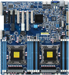
High Performance Server Board with Dual Intel Xeon Processors, RDIMM/UDIMM/LRDIMM RAM, VGA, 2 GbE LA...
Request a Quote

The quote request has been received
Close

Facing challenges or have inquiries? Feel free to contact us!
Call Us +1-469-283-2440
What they say about us
FANTASTIC RESOURCE
One of our top priorities is maintaining our business with precision, and we are constantly looking for affiliates that can help us achieve our goal. With the aid of GID Industrial, our obsolete product management has never been more efficient. They have been a great resource to our company, and have quickly become a go-to supplier on our list!
Bucher Emhart Glass
EXCELLENT SERVICE
With our strict fundamentals and high expectations, we were surprised when we came across GID Industrial and their competitive pricing. When we approached them with our issue, they were incredibly confident in being able to provide us with a seamless solution at the best price for us. GID Industrial quickly understood our needs and provided us with excellent service, as well as fully tested product to ensure what we received would be the right fit for our company.
Fuji
HARD TO FIND A BETTER PROVIDER
Our company provides services to aid in the manufacture of technological products, such as semiconductors and flat panel displays, and often searching for distributors of obsolete product we require can waste time and money. Finding GID Industrial proved to be a great asset to our company, with cost effective solutions and superior knowledge on all of their materials, it’d be hard to find a better provider of obsolete or hard to find products.
Applied Materials
CONSISTENTLY DELIVERS QUALITY SOLUTIONS
Over the years, the equipment used in our company becomes discontinued, but they’re still of great use to us and our customers. Once these products are no longer available through the manufacturer, finding a reliable, quick supplier is a necessity, and luckily for us, GID Industrial has provided the most trustworthy, quality solutions to our obsolete component needs.
Nidec Vamco
TERRIFIC RESOURCE
This company has been a terrific help to us (I work for Trican Well Service) in sourcing the Micron Ram Memory we needed for our Siemens computers. Great service! And great pricing! I know when the product is shipping and when it will arrive, all the way through the ordering process.
Trican Well Service
GO TO SOURCE
When I can't find an obsolete part, I first call GID and they'll come up with my parts every time. Great customer service and follow up as well. Scott emails me from time to time to touch base and see if we're having trouble finding something.....which is often with our 25 yr old equipment.
ConAgra Foods