

 Manufacturers
AAEON PCM-4894 REV A 2.2
Description
All-in-One 486 single Board computer with Flat Panel / CRT SVGA, Ethernet, and 4 Serial Ports
Part Number
PCM-4894 REV A 2.2
Price
Request Quote
Manufacturer
AAEON
Lead Time
Request Quote
Category
Single Board Computers
Specifications
System Chipset
ALi 1487/1489
Ethernet Chipset
Realtek RTL8029AS
Video Chipset
C&T 65550
Form Factor
EBX
Datasheet

Extracted Text
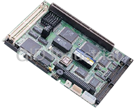
PCM-4894
All-in-One 486 single Board computer
with Flat Panel / CRT SVGA, Ethernet,
and 4 Serial Ports
Copyright Notice
This document is copyrighted, 1999, by AAEON Technology Inc.
All rights are reserved. AAEON Technology Inc. reserves the right
to make improvements to the products described in this manual at
any time without notice.
No part of this manual may be reproduced, copied, translated, or
transmitted in any form or by any means without the prior written
permission of AAEON Technology Inc. Information provided in
this manual is intended to be accurate and reliable. However,
AAEON Technology Inc. assumes no responsibility for its use, nor
for any infringements upon the rights of third parties which may
result from its use.
Acknowledgements
AMD is a trademark of Advanced Micro Devices, Inc.
AMI is a trademark of American Megatrends, Inc.
Award is a trademark of Award Software International, Inc.
Cyrix is a trademark of Cyrix Corporation.
IBM, PC/AT, PS/2, and VGA are trademarks of International
Business Machines Corporation.
Intel and Pentium are trademarks of Intel Corporation.
®
Microsoft Windows is a registered trademark of Microsoft Corp.
SMC is a trademark of Standard Microsystems Corporation.
RTL is a trademark of Realtek Semi-Conductor Co., Ltd.
C&T is a trademark of Chips and Technologies, Inc.
UMC is a trademark of United Microelectronics Corporation.
ITE is a trademark of Integrated Technology Express, Inc.
SIS is a trademark of Silicon Integrated Systems Corp.
VIA is a trademark of VIA Technology, Inc.
All other product names or trademarks are properties of their
respective owners.
Part No. 2047489420 PCM-4894 Rev.A2.2 1st Edition
Prepared in Taiwan, April 1999
Packing list
Before you begin installing your card, please make sure that the
following materials have been shipped:
• 1 PCM-4894 Single board computer
• 1 Quick Installation Guide
• 1 CD-ROM contains the followings:
-- User's Manual (this manual in PDF file)
-- VGA drivers and utilities
-- Ethernet drivers and utilities
-- Latest BIOS (as of this CD-ROM was made)
• PC/104 Module mounting support kit
The PCM-4894 require several cables for operation. You can make
them yourself or purchase an optional cable kit, PCM-10489-1 (Part
No : 9969048900).
If any of these items are missing or damaged, contact your
distributor or sales representative immediately.
Notice
Dear Customer,
Thank you for purchasing the PCM-4894 board. The user's
manual is designed to help you to get the most out of the PCM-
4894, please read it thoroughly before you install and use the
board. The product that you have purchased comes with a one-
year limited warranty, but AAEON will not be responsible for any
misuse of the product. Therefore, we strongly urge that you first
read the manual before using the product.
To receive the lastest version of the user's manual, please visit our
Web site at:
http://www.aaeon.com
Contents
Chapter 1: General Information ................................ 1
Introduction ............................................................................ 2
Specifications .......................................................................... 3
Board layout ........................................................................... 6
Dimensions .............................................................................. 7
Chapter 2: Installation................................................ 9
Jumpers and connectors ...................................................... 10
Locating jumpers and connectors ........................................ 11
Setting jumpers ..................................................................... 12
Safety precautions ................................................................ 13
Installing DRAM (SIMMs) .................................................. 14
Installing SIMMs .................................................................... 14
Removing SIMMs ................................................................... 14
Ethernet connector (CN1) .................................................... 15
Serial ports connector (CN2) ............................................... 16
COM 1-4 RS-232/422/485 serial ports (CN2) ........................ 16
Parallel port connector (CN3) ............................................. 17
IDE hard drive connector (CN4) ......................................... 18
Floppy drive connector (CN5) ............................................. 20
Connecting the flopy drive ...................................................... 20
Power connector (CN6, CN17, CN18) ................................ 21
Keyboard and PS/2 mouse connectors (CN7) .................... 22
Power LED and keylock (CN8) ........................................... 23
Reserved IR connector (CN9) .............................................. 23
Digital I/O connector (CN10) .............................................. 24
LED indicators / Hardware reset (CN13) ............................ 25
Buzzer or external speaker (CN14) ..................................... 26
LCD connector (CN15) ........................................................ 27
VGA connectors (CN16) ...................................................... 28
COM3/4 RI function selection (JP1) .................................. 29
DOC address setting (JP2, 1-6) ....................................... 30
COM2 RS-232/422/485 select (JP2, 7-10) ..................... 30
LCD panel's voltage setting (JP4) ................................... 31
LCD SHF/ASHF clock select (JP5) ................................. 31
DiskOnChip socket (U20) ................................................. 32
Chapter 3: Award Setup ............................................. 33
System test and initialization ............................................. 34
System configuration verification ............................................ 34
Award BIOS setup .............................................................. 35
Entering setup .......................................................................... 35
Standard CMOS setup ....................................................... 36
BIOS features setup ........................................................... 38
CHIPSET features setup ................................................... 41
Power management setup.................................................. 42
PCI configuration setup ..................................................... 47
Load BIOS defaults / Load setup defaults ...................... 49
Chpater 4: Flat Panel/CRT Controller Display Drivers
and Utilities ............................................. 51
Software drivers .................................................................. 52
Hardware configuration .......................................................... 52
Necessary prerequisites ..........................................................53
Before you begin .....................................................................53
Windows 95 .......................................................................... 54
Windows 3.1......................................................................... 55
Changing color schemes.......................................................... 56
Software utilities.................................................................. 57
The CHIPSDSP utility program ..............................................57
The CHIPSCPL utility program ..............................................59
Installing the utility ................................................................... 59
How to use the utility .............................................................. 59
Chapter 5: Ethernet Software Configuration ............ 61
Ethernet software configuration ....................................... 62
Appendix A: Watchdog Timer Demo Program ........... 63
How to program the WATCHDOG TIMER ................... 64
Demo program in C ............................................................ 65
Appendix B: Installing PC/104 Modules ....................... 67
Installing PC/104 modules................................................. 68
Appendix C: Optional Extras ....................................... 71
PCM-10489-1 Cable kit for PCM-4894 .......................... 72
1
General
Information
This chapter provides background
information for the PCM-4894.
Sections include:
• Specifications
• Board layout
• Dimensions
Chapter 1 General Information 1
CHAPTER
Introduction
The PCM-4894 is an all-in-one single board 486 computer with
an onboard flat panel/CRT SVGA controller and PCI Ether-
net interface. It offers all the functions of an industrial comput-
er and its display capabilities on a single board, but fits in the
space of a 5.25" floppy drive (only 5.75" x 8"). This means the
PCM-4894 is your absolute best solution for embedded applica-
tions.
The onboard PCI-bus, flat panel/CRT SVGA controller uses the
CHIPS 65550 chipset with up to 2 MB of video memory (on-
board 1MB). This chipset, used with the local PCI-bus, enables
32-bit graphic throughput at up to 33 MHz. Excellent for display-
intensive applications, it supports various LCD types including
TFT, STN, B/W, and EL.
The onboard Ethernet Realtek RTL 8029AS PCI bus Ethernet
controller supports remote boot ROM functions.
The PCM-4894 supports the M-Systems DiskOnChip 2000
(optional) which is a new generation of high performance single-
chip Flash Disk. It provides a Flash Disk (as a BIOS expansion)
which does not require any bus, slots, or connectors. It is also the
optimal solution for Single Board Computers because of its small
size, easy integration, plug-and-play functionality, and its low
power consumption. The DiskOnChip is available in capacities
from 2MB to 72MB and fits in a standard 32-pin DIP socket.
Another feature of the PCM-4894 is the inclusion of a high
speed, local bus IDE controller. This controller supports (through
ATA PIO) mode 3 and mode 4 hard disks, enabling data transfer
rates in excess of 11 MB/second. Up to two IDE devices can be
connected, including large hard disks, CD-ROM drives, tape
backup drives, or other IDE devices. The built-in, enhanced IDE
controller provides a 4-layer, 32-bit, posted write buffer and a 4-
layer, 32-bit read-prefetch buffer to boost IDE performance.
2 PCM-4894 User Manual
Specifications
Standard SBC functions
CPU: AMD 5X86-P75 (486DX5-133) SQFP
BIOS: Award 128KB FLASH BIOS
Chipset: ALI 1487/1489
Super I/O Chipset: WINBOND83877TF
nd nd
2 Level Cache: On board 128KB 2 level cache. Could be
upgraded to 512KB by factory.
RAM memory: 4MB to 128MB. Two 72-pin SIMM sockets on
board.
Enhanced IDE hard disk drive interface: Support up to two
hard disk drives. BIOS auto-detect. Supports PIO mode 4 and Bus
Master. 22 x 2 header, pitch 2.00mm with housing.
Floppy disk drive interface: Supports up to two floppy disk
drives, 5.25" (360KB and 1.2MB) and /or 3.5" (720KB, 1.44MB
and 2.88MB). 17 x 2 header, pitch 2.54mm with housing.
Multi-mode parallel port: Configured to LPT1, LPT2, LPT3 or
disabled. Supports SPP, ECP and EPP. 13 x 2 header, pitch
2.54mm with housing.
Serial ports: Three RS-232 and one RS-232/422/485 serial
ports. Ports can be configured as COM1, COM2, COM3, COM4
or disabled individually. Four 16C550 serial UARTs. 20 x 2
header, pitch 2.54mm with housing for RS-232 x 4.
Keyboard/mouse connector: 8 pin connector supports standard
PC/AT keyboard and PS/2 mouse.
Real Time Clock/Calendar: Dallas DS-12887A or equivalent,
powered by lithium battery for data retention of up to 10 years.
Chapter 1 General Information 3
Watchdog Timer: Can generate a system reset, IRQ15. Support
Windows 3.1, Windows 95. Software selectable timeout interval.
(1 ~ 255 sec., 1 sec./step)
DMA channels: 7
Interrupt levels: 15
Power connector: 4 pin 3.5” HDD male power connector.
Power management: I/O peripheral devices support power saving
and doze/standby/suspend modes. APM 1.1 compliant.
Flat panel VGA interface
Chipset: C&T65550
Display memory: 2MB on board.
Display type: Supports CRT and flat panel (TFT, DSTN, mono
and EL) display. Can display both CRT and flat panel simulta-
neously.
Resolution: Up to 1024x768@64K colors.
Ethernet interface
Chipset: Realtek RTL8029AS PCI Ethernet controller.
Ethernet interface: On board RJ-45 connector. Software drivers
optional. Supports boot ROM function.
SSD interface
One 32-pin DIP socket supports M-system DiskOnChip 2000
series, memory capacity from 2MB to 72MB.
4 PCM-4894 User Manual
Digital I/O interface
4 TTL Digital Input bits & 4 Open Collector Digital Output bits.
(Port address : 294H, Bit : 0, 1, 2, 3)
Expansion Slots
PC/104 connector: 104 pin connector for a 16 bit bus expan-
sion. One PCI/ISA bus slot.
Mechanical and environmental
Power supply voltage: +5V (4.75V to 5.25V)
Max. power requirements: +5V @ 4A
Operating temperature: 32 to 140° F (0 to 60° C)
Board Size: 8”(L) x 5.75”(W) (203mm x 146mm)
Weight: 1.32 lb. (0.6 Kg)
Chapter 1 General Information 5
AM486DX5
R T C DiskOnChip
Board layout
Winbond
Winbond
6 PCM-4894 User Manual
XILINX
XC9572
ALI
M1487A1
20F001N
RTL8029AS
ALI
M1489 B1
CHIPS
F65550
Card dimensions
5.08
3.56
40.64
97.16
100.97
119.38
174.63
177.17
193.04
198.12
203.20
Chapter 1 General Information 7
5.08
9.53
95.25
135.89
140.97
146.05
8 PCM-4894 User Manual
2
Installation
This chapter explains set up procedures
for the PCM-4894 hardware, including
instructions on setting jumpers and
connecting peripherals, switches and
indicators. Be sure to read all safety
precautions before you begin the installa-
tion procedure.
Chapter 2 Installation 9
CHAPTER
Jumpers and connectors
Connectors on the board link it to external devices such as hard
disk drives, a keyboard, or floppy drives. In addition, the board has
a number of jumpers that allow you to configure your system to
suit your application.
The table below lists the function of each of the board jumpers and
connectors:
Jumpers and connectors
Label Function
CN1 Ethernet connector
CN2 Serial ports connector
CN3 Parallel port connector
CN4 HDD connector
CN5 FDD connector
CN6 Main power connector
CN7 Keyboard / PS2 mouse connector
CN8 Power LED / Keyboard lock
CN9 Reserved IR connector
CN10 Digital I/O connector
CN13 LED indicators / Hardware reset
CN14 External speaker connector
CN15 LCD connector
CN16 VGA connector
CN17 Auxiliary power connector
CN18 CPU fan power connector
JP1 COM3/4 RI function selection
JP2 DOC address / COM2 mode setting
JP4 LCD voltage selection
JP5 LCD SHF/ASHF clock selection
U20 DiskOnChip socket
10 PCM-4894 User Manual
AM486DX5
R T C DiskOnChip
Locating jumpers and connectors
CN18
CN16
PCI/ISA
Riser Card
Slot
JP4
CN15
JP3
JP5
CN14
CN13
U20
CN12
CN9
CN8
CN17
JP2
CN7
Winbond
CN10
Winbond
CN6
CN1
CN4 JP1
CN5 CN2 CN3
Chapter 2 Installation 11
XILINX
XC9572
ALI
M1487A1
20F001N
RTL8029AS
ALI
M1489 B1
CHIPS
F65550
Setting jumpers
You configure your card to match the needs of your application by
setting jumpers. A jumper is the simplest kind of electric switch.
It consists of two metal pins and a small metal clip (often
protected by a plastic cover) that slides over the pins to connect
them. To close a jumper you connect the pins with the clip. To
"open" a jumper you remove the clip. Sometimes a jumper will
have three pins, labeled 1, 2, and 3. In this case you would
connect either pins 1 and 2 or 2 and 3.
3
2
1
Open Closed Closed 2-3
The jumper settings are schematically depicted in this manual as
follows:
1 2 3
Open Closed Closed 2-3
A pair of needle-nose pliers may be helpful when working with
jumpers.
If you have any doubts about the best hardware configuration for
your application, contact your local distributor or sales represen-
tative before you make any changes.
12 PCM-4894 User Manual
Safety precautions
Warning! Always completely disconnect the power cord
from your chassis whenever you are working on
it. Do not make connections while the power is
on because sensitive electronic components can
be damaged by the sudden rush of power. Only
experienced electronics personnel should open
the PC chassis.
Caution! Always ground yourself to remove any static
charge before touching the CPU card. Modern
electronic devices are very sensitive to static
electric charges. Use a grounding wrist strap at
all times. Place all electronic components on a
static-dissipative surface or in a static-shielded
bag when they are not in the chassis.
Chapter 2 Installation 13
Installing DRAM (SIMMs)
The PCM-4894 CPU card provides two 72-pin SIMM (Single In-
line Memory Module) sockets and supports between 4MB and
64MB.
When installing SIMMs, make sure that Bank 1 is filled first.
Installing SIMMs
Note: that the modules can only fit into a socket one way.
1. Insert the memory module into the socket at a moderate angle.
2. Push the module toward the vertical posts at both ends of the
socket until the module is upright and the retaining clips at
both ends of the module click into place. When positioned
correctly, the pins on top of the vertical posts should corre-
spond to the circular holes on the ends of the module.
3. Repeat steps 1 and 2 for each module you install.
Removing SIMMs
If you need to remove a SIMM, follow the procedures below:
1. Supporting the SIMM with a finger, use a pen or a similarly
shaped object and press one retaining clip straight down.
2. Repeat for the other side. When released, the retaining clips
will push the SIMM up and out of its upright position.
3. Carefully pull the SIMM out of the socket with your fingers.
4. Repeat the above steps for each module you remove.
14 PCM-4894 User Manual
Ethernet connector (CN1)
The Ethernet connects to the PCM-4894 via an adapter cable to a
10-pin polarized header (CN1). For 10Base-T RJ-45 operation,
an adapter cable converting CN1 into a standard RJ-45 jack is
required.
Ethernet connector (CN1)
Pin Signal
1 +5V
2 Link LED
3 RX+
4 RX-
5 RX LED
6 GND
7NC
8 GND
9 TX+
10 TX-
Chapter 2 Installation 15
Serial ports connector (CN2)
The mainboard offers four serial ports: three RS-232 and one RS-
232/422/485. These ports allow you to connect them to serial
devices (mouse, printers, etc.).
COM 1-4 RS-232/422/485 serial ports (CN2)
COM1, COM2, COM3, COM4 RS-232/422/485 serial port (CN2)
PIN SIGNAL PIN SIGNAL
COM1 1 DCDA 2 DSRA
3 RXDA 4 RTSA
5 TXDA 6 CTSA
7 DTRA 8 RIA
9 GND 10 N.C.
COM2 11 DCDB 12 DSRB
(422TXD-/485DATA-)
13 RXDB 14 RTSB
(422TXD+/485DATA+)
15 TXDB 16 CTSB
(422RXD+)
17 DTRB 18 RIB
(422RXD-)
19 GND 20 N.C.
COM3 21 DCDC 22 DSRC
23 RXDC 24 RTSC
25 TXDC 26 CTSC
27 DTRC 28 RIC/+5V/+12V
29 GND 30 N.C.
COM4 31 DCDD 32 RSRD
33 RXDD 34 RTSD
35 TXDD 36 CTSD
37 DTRD 38 RID/+5V/+12V
39 GND 40 N.C.
16 PCM-4894 User Manual
Parallel port connector (CN3)
Normally, the parallel port is used to connect the card to a printer.
The PCM-4894 includes an onboard parallel port, accessed
through the CN3 connector, a 26-pin flat-cable connector. The
CPU card comes with an adapter cable, which lets you use a
traditional DB-25 connector. The cable has a 26-pin connector
on one end and a DB-25 connector on the other.
Pin assignments
Parallel port connector (CN3)
Pin Signal Pin Signal
1 Strobe 14 -Auto feed
2 Data 0 15 -Error
3 Data 1 16 -Init printer
4 Data 2 17 -Select input
5 Data 3 18 GND
6 Data 4 19 GND
7 Data 5 20 GND
8 Data 6 21 GND
9 Data 7 22 GND
10 -Acknowledge 23 GND
11 Busy 24 GND
12 Paper empty 25 GND
13 +Select
Chapter 2 Installation 17
IDE hard drive connector (CN4)
You can attach two Enhanced Integrated Device Electronics hard
disk drives to the PCM-4894's internal controller. The card
comes with a 40-pin flat piggyback cable. This cable has one 44-
pin 2.0mm pitch and two identical 40-pin flat-cable connectors.
Connecting the hard drive
Usually, wire number 1 on the cable is red or blue, and the other
wires are gray.
1. Connect one end of the cable to the IDE connector. Make
sure that the red (or blue) wire corresponds to pin 1 on the
connector, which is labeled on the board.
2. Plug the other end of the cable to the Enhanced IDE hard
drive, with pin 1 on the cable corresponding to pin 1 on the
hard drive. (See your hard drive's documentation for the
location of the connector.)
Unlike floppy drives, you can make the connections with any of
the connectors on the cable. If you install two drives, you will
need to set one as the master and one as the slave. You do this
using jumpers on the drives. If you install just one drive, set it as
the master.
18 PCM-4894 User Manual
Pin assignments
The following table lists the pin numbers and their respective
signals:
IDE Connector (CN4)
Pin Signal Pin Signal
1 Reset 2 GND
3D7 4 D8
5D6 6 D9
7 D5 8 D10
9D4 10 D11
11 D3 12 D12
13 D2 14 D13
15 D1 16 D14
17 D0 18 D15
19 GND 20 N.C.
21 N.C. 22 GND
23 IOW 24 GND
25 IOR 26 GND
27 IORDY 28 NC
29 N.C. 30 GND
31 IRQ 14 32 -I/O CS16
33 A1 34 N.C.
35 A0 36 A2
37 CS0 38 CS1
39 -ACT 40 GND
41 +5V 42 +5V
43 NC 44 GND
Chapter 2 Installation 19
Floppy drive connector (CN5)
You can attach up to two floppy disks to the PCM-4894's on-
board controller. You can use any combination of 5 1/4" (360 KB
and 1.2 MB) and/or 3 1/2" (720 KB, 1.44 MB, and 2.88 MB)
drives.
The PCM-4894 CPU card comes with a 34-pin daisy-chain drive
connector cable. On one end of the cable is a 34-pin flat-cable
connector. There are two sets of floppy disk drive connectors,
one in the middle, and one on the other end. Each set consists of
a 34-pin flat-cable connector (usually used for 3.5" drives) and a
printed-circuit board connector (usually used for 5.25" drives).
Connecting the floppy drive
1. Plug the 34-pin flat-cable connector into the CN5 connector.
2. Attach the appropriate connector on the other end of the cable
to the floppy drive(s). You can use only one connector in the
set. The set on the end (after the twist in the cable) connects
to the A: floppy. The set in the middle connects to the B:
floppy.
Pin assignments
The following table lists the pin assignments for the CN5 connec-
tor:
FLOPPY drive connector (CN5)
Pin Signal Pin Signal
1~33 (odd) GND 2 High density
4 +5V 6 High density
8 Index 10 Motor enable A
12 Driver select B 14 Driver select A
16 Motor enable B 18 Direction
20 Step pulse 22 Write data
24 Write enable 26 Track 0
28 Write protect 30 Read data
32 Select head 34 Disk change
20 PCM-4894 User Manual
Power connector (CN6, CN17, CN18)
Main power connector (CN6)
Main power conector (CN6)
Pin Signal
1 +12V
2 GND
3 GND
4 +5V
Auxiliary power connector (CN17)
Auxiliary power connector (CN17)
Pin Signal
1 -12V
2 GND
3 GND
4 -5V
CPU fan power connector (CN18)
CPU fan power connector (CN18)
Pin Signal
1 +5V
2 GND
Chapter 2 Installation 21
Keyboard and PS/2 mouse connectors
(CN7)
The mainboard provides a keyboard connector which supports
both a keyboard and a PS/2 style mouse. In most cases, especially
in embedded applications, a keyboard is not used. The standard
PC/AT BIOS will report an error or fail during power-on self-test
(POST) after a reset if the keyboard is not present. The mainboard
BIOS Advanced setup menu allows you to select "System Key-
board" under the "Present" or "Absent" selection. This allows no-
keyboard operation in embedded system applications without the
system halting under POST (power-on-self-test).
Keyboard and PS/2 mouse connector (CN7)
Pin Signal
1 GND
2 MS V
CC
3 MS DATA
4 MS CLOCK
5 GND
6 KB V
CC
7 KB DATA
8 KB CLOCK
22 PCM-4894 User Manual
Power LED and keylock (CN8)
You can connect an LED to indicate when the CPU card is on. Pin
1 of CN8 supplies power to the LED; Pin 3 is the ground.
You can use a switch (or a lock) to disable the keyboard. In this
state, the PC will not respond to any input. This is useful if you
do not want anyone to change or stop a running program. Simply
connect the switch between Pins 4 and 5. The pin assignments
appear in the following table:
Power LED and keylock (CN8)
Pin Function
1 LED Power (+5 V)
2NC
3 GND
4 Keyboard lock
5 GND
Reserved IR connector (CN9)
Reserved IR connector (CN9)
Pin Function
1 Vcc
2 FIR_RX
3 IR_RX
4 GND
5 IR_TX
Chapter 2 Installation 23
Digital I/O connector (CN10)
The digital I/O interface of PCM-4894 provides 4 TTL input bits
& 4 Open-Collector output bits. The following table lists the pin
assignment for CN10.
Digital I/O (DIO) connector (CN10)
Pin Function
1 TTL Input Bit 0
2 O.C. Output Bit 0
3 TTL Input Bit 1
4 O.C. Output Bit 1
5 TTL Input Bit 2
6 O.C. Output Bit 2
7 TTL Input Bit3
8 O.C. Output Bit3
9 +5V
10 GND
24 PCM-4894 User Manual
LED indicators / Hardware reset (CN13)
Ethernet link signal LED (CN13, 1-2)
A continuously lit LED indicates good linkage between the PCM-
4894 and its supporting hub.
Ethernet active signal LED (CN13, 3-4)
A flashing LED indicates that the PCM-4894 is transmitting or
receiving data.
HDD LED (CN13, 5-6)
A flashing LED indicates that PCM-4894 is accessing the hard
drive.
Hardware reset (CN13, 9-10)
The following table lists the pin assignment of CN13:
LED indicators / Hardware reset (CN13)
Pin Signal
1 LAN Link
2 +5V
3 LAN Active
4 +5V
5 HDD LED
6 +5V
7 Reserved
8 GND
9 Reset
10 GND
Chapter 2 Installation 25
Buzzer or external speaker (CN14)
The CPU card has its own buzzer. You can disable the internal
buzzer and connect an external speaker to CN14. Enabling the
external speaker automatically disables the internal buzzer.
Buzzer or External Speaker
Buzzer External Speaker
1 2 3 4 1 2 3 4
1 2 3 4
OR
Buzzer or External speaker (CN14)
Pin Function
1 Vcc
2 Speaker output
3 Buzzer in
4 Speaker output
26 PCM-4894 User Manual
LCD connector (CN15)
The board also features an LCD connector (CN15), which allows
you to connect various flat panel displays. The following table lists
their pin assignments:
LCD connector (CN15)
Pin Signal Pin Signal
1 +12 V 2 +12 V
DC DC
3 GND 4 GND
5 Vcc(+5V/+3.3V) 6 Vcc(+5V/+3.3V)
7 ENA VEE 8 GND
9P0 10 P1
11 P2 12 P3
13 P4 14 P5
15 P6 16 P7
17 P8 18 P9
19 P10 20 P11
21 P12 22 P13
23 P14 24 P15
25 P16 26 P17
27 P18 28 P19
29 P20 30 P21
31 P22 32 P23
33 GND 34 GND
35 SHFCLK 36 FLM (V SYS)
37 M 38 LP (H SYS)
39 GND 40 ENABKL
41 NC 42 /ASHFCLK
SHFCLK
43 NC 44 NC
Chapter 2 Installation 27
VGA connectors (CN16)
The PCM-4894 CPU card's SVGA connector (CN16) with PCI
bus supports monochrome display as well as high resolution
color displays.
SVGA connector (CN16)
Pin Signal Pin Signal
1 Red video 9 Key (no pin)
2 Green video 10 Sync return (GND)
3 Blue video 11 Monitor ID (not used)
4 Not used 12 Monitor ID (not used)
5 GND 13 Horizontal sync
6 Red return (GND) 14 Vertical sync
7 Green return (GND) 15 Not used
8 Blue return (GND) 16 NC
28 PCM-4894 User Manual
COM3/4 RI function selection (JP1)
You can set the RI function mode of COM3/4 via JP1. The
available configurations are as follows:
COM3/COM4 RI function selection
2 4 6 8 10 12
* *
1 3 5 7 9 11
1-2* COM3 RI = RI function
3-4 COM3 RI = +5V output
5-6 COM3 RI = +12V output
7-8* COM4 RI = RI function
9-10 COM4 RI = +5V output
11-12 COM4 RI = +12V output
* default
Chapter 2 Installation 29
DOC address setting (JP2, 1-6)
The DiskOnChip 2000 occupies a 8 KB window in the upper
memory address range of C800 to E000. You should ensure this
does not conflict with any other device's memory address. JP2
pin 1-6 controls the memory address of the Flash disk.
DOC address setting (JP2, 1-6)
CC00 D000 D400
2 4 6 2 4 6 2 4 6
1 3 5
1 3 5 1 3 5
D800 DC00 E000
2 4 6
2 4 6 2 4 6
*
1 3 5 1 3 5
1 3 5
* default
COM2 RS-232/422/485 select (JP2, 7-10)
The serial port COM2 of this board can be configured as RS-232,
RS-422, or RS-485.
The settings are as follows:
COM2 RS-232/422/485 select (JP2, 7-10)
RS-232 RS-422 RS-485
7 8 7 8
* 7 8
9 10 9 10
9 10
* default
30 PCM-4894 User Manual
LCD panel’s voltage setting (JP4)
You can select the LCD connector (CN15) driving voltage by
setting JP4. The configuration is as follows:
LCD panel’s voltage setting (JP4)
3.4 V 5 V
1 2 3 1 2 3
*
* default
LCD SHF/ASHF clock select (JP5)
You can select the LCD control signals by setting JP5. The
following charts show the available options.
LCD SHF/ASHF Clock select (JP5)
SHF CLK from C&T65550 ASHF CLK
*
1 2 3 1 2 3
* default
Chapter 2 Installation 31
DiskOnChip socket (U20)
The DiskOnChip 2000 family of products provides a single chip
solid-state flash disk in a standard 32-pin DIP package. The
DiskOnChip 2000 is a solid-state disk with no moving parts,
resulting in a significant reduction in power consumption and an
increase in reliability. The DiskOnChip is a small, plug and play
Flash disk. It is easy to use and saves integration overhead.
The DiskOnChip 2000 family of products is available in capaci-
ties ranging from 2MB up to 72 MB, unformatted. In order to
manage the disk, the DiskOnChip 2000 includes the TrueFFS, M-
Systems' Flash File System proprietary software. The DiskOn-
Chip 2000 package is pin-to-pin compatible with standard 32-pin
EPROM devices.
pin
Description Pin Number Direction Note
Name
A0-A12 Address bus 4-12,23,25-27 Inputs
A13-A16 Address bus 2,3,28,29 Inputs 1
D0-D7 Data bus 13-15,17-21 I/O
CE/ Chip Enable 22 Input
OE /
OE/ Output Enable 24 Input
WE/ Write Enable 31 Input
NC Not connected 1.30 2
VCC Power 32
GND Ground 16
Figure1-MD2200 Pin-out Note 1: Pins A13 through A16 are not
used by the MD2200. They are kept for
socket backward compatibility with ED
1100 (DiskOnChip 1000)
Note 2: Pins 1 and 30 are not used by
MD2200
32 PCM-4894 User Manual
3
Award BIOS Setup
This chapter describes how to configure
the BIOS for the PCM-4894.
Chapter 3 Award BIOS Setup 33
CHAPTER
System test and initialization
These routines test and initialize board hardware. If the routines
encounter an error during the tests, you will either hear a few
short beeps or see an error message on the screen. There are two
kinds of errors: fatal and nonfatal. The system can usually
continue the boot up sequence with nonfatal errors. Nonfatal
error messages usually appear on the screen along with the
following instructions:
press immediately. This will
allow you to enter the utility and the utility screen should appear
(below).
Setup Utility Initial Screen
Award’s BIOS ROM has a built-in setup utility that allows users to
modify the basic system configuration. This type of information
is stored in a battery-backed CMOS RAM so that the information
is retained when the power is turned off.
Many fields in the setup screens have on-line help descriptions
available: press F1 to access this help.
Chapter 3 Award BIOS Setup 35
Standard CMOS setup
When you choose the STANDARD CMOS SETUP option from
the INITIAL SETUP SCREEN menu, the screen below is dis-
played. This standard setup menu allows users to configure
system components such as the date, time, hard disk drive, floppy
drive, display, and memory. Online help for each field can be
accessed by pressing F1.
CMOS setup screen
Date and Time Configuration
Select the Date and Time in the Standard setup. The current values
for each category are displayed. Enter new values through the
keyboard.
Floppy A, Floppy B
Select these icons to configure the type of floppy drive that is
attached to the system: 360 KB 5 1/4", 1.2 MB 5 1/4", 720 KB 3
1/2", 1.44 MB 3 1/2", and/or 2.88 MB 3 1/2". The settings have
not been pre-installed.
36 PCM-4894 User Manual
LCD & CRT
In the display selection item, you can use PageUp/PageDown key
to select Both , LCD, CRT or Auto.
Pannel:
This selection item allow user to select LCD BIOS to match the
LCD types. There are eight LCD types available for users to
select as their LCD display modes as below:
Brand
Mt odel nameForma
name
S0harpLN X15X81024x768DST
SPharpLO M64183640x480MON
SPharpLN M64C35640x480DST
S0harpLN M12S4800x600DST
640x480TFT
N0ECNL6448AC33-1
(12bits)
640x480
TAoshibaLTM10C209
(18bits)TFT
N4 ECNT L8060AC26-0800x600TF
1024x768TFT
S3harp14x0
(36bits)
Chapter 3 Award BIOS Setup 37
BIOS features setup
By choosing the BIOS FEATURES SETUP option from the
INITIAL SETUP SCREEN menu, the screen below is displayed.
The displayed configuration is based on the manufacturer's
SETUP DEFAULTS settings.
BIOS features setup
Virus Warning
When this item is enabled, the Award BIOS will monitor the boot
sector and partition table of the hard disk drive for any modifica-
tion attempts. If an attempt is made, the BIOS will halt the system
and the following error message will appear. Afterwards, you can
run an anti-virus program to locate and remove the problem
before any damage is done.
! WARNING !
Disk boot sector is to be modified
Type "Y" to accept write or "N" to abort write
Award Software, Inc.
38 PCM-4894 User Manual
CPU Internal Cache/External Cache
These two categories, if enabled, can speed up memory access.
However, it depends on the CPU/chipset design.
Quick Power On Self Test
This category speeds up Power On Self Test (POST) after you
power up the computer. If it is set to Enabled, BIOS will shorten
or skip some check items during POST.
Boot Sequence
This category determines which drive to search first for the
operating system.
Swap Floppy Drive
This item allows you to swap the floppy drive assignments so that
drive A is treated as drive B and drive B is treated as drive A under
DOS. The default setting is Disabled.
Boot Up Floppy Seek
During POST, the BIOS will determine if the floppy disk drive
installed is 40 or 80 tracks. 360KB type is 40 tracks while
760KB, 1.2MB, and 1.44MB are all 80 tracks.
Boot Up NumLock Status
This allows you to determine the default state of the numeric
keypad on an IBM-compatible extended keyboard.
Boot Up System Speed
This allows you to determine the Boot Up Speed. The choices are
High/Low.
Chapter 3 Award BIOS Setup 39
Gate A20 Option
This entry allows you to select how gate A20 is handled. Gate
A20 is a device used to address memory above 1 MB. Initially,
gate A20 was handled via a pin on the keyboard. Today keyboards
still provide this support, however it is more common and much
faster for the system chipset to provide support for gate A20.
The choices are thus: Normal and Fast.
Security Option
This category allows you to limit access to the system. The
choices are System: which requires a password at boot up and
Setup: which only requires a password to access the setup utility.
Video BIOS Shadow
Determines whether the video display card BIOS will be copied
into system DRAM in order to increase display speed and is
required for system performance. However, it is optional
depending on the chipset design. The default setting is Enabled.
Shadowing Address Ranges
The next 3 lines, from C8000-CBFFF Shadow to DC000-DFFFF
Shadow are address ranges for shadowing other expansion card
ROMs. If there are any expansion cards with ROMs installed in
your system, you have to know the address range they use in order
to shadow them specifically. The default setting for all of these is
Disabled.
40 PCM-4894 User Manual
CHIPSET features setup
By choosing the BIOS FEATURES SETUP option from the
INITIAL SETUP SCREEN menu, the screen below is displayed.
The displayed configuration is based on the manufacturer's
SETUP DEFAULTS settings.
CHIPSET features setup
This section allows you to configure the system based on the
specific features of the installed chipset. This chipset manages
bus speeds and access to system memory resources, such as
DRAM and the external cache. It also coordinates communica-
tions between the conventional ISA bus and the PCI bus. It must
be stated that these items should never need to be altered. The
default settings have been chosen because they provide the best
operating conditions for your system. The only time you might
consider making any changes would be if you discovered that data
was being lost while using your system.
Because of the complexity and technical nature of some of the
options, not all of the options are described here.
Chapter 3 Award BIOS Setup 41
Power management setup
By choosing the POWER MANAGEMENT SETUP option from
the initial SETUP SCREEN menu, the screen below is displayed.
The displayed configuration is based on the manufacturer's
SETUP DEFAULTS settings.
Power management setup
Power Management
Power management lets you set up your computer to save
electricity when it is not actively in use by putting the system into
progressively greater power saving modes. In the power manage-
ment scheme there are four system states which proceed in the
following sequence:
Normal � Doze � Standby � Suspend
42 PCM-4894 User Manual
There are four selections for Power Management (PM):
Disabled Turns off PM
Max Saving Maximized power saving by activating
maximum power saving settings after one
minute of system inactivity.
Min Saving Produces less power saving by activating
moderate power saving settings after one hour
of system inactivity.
User Defined You set the power saving options manually.
With the exception of Disabled, three of the above selections
have "fixed-mode" settings. Therefore, when PM is set to
Disabled, some items which are predefined will become unmodi-
fiable.
PM Control by APM
When this is set to Yes, the Advanced Power Management feature
in Microsoft Windows controls power management operation.
The default setting is No.
Video Off Option
User can select 4 different modes for turning off the video. The
modes are a function of the PM mode of the computer. The
choices are All Modes�Off, Always On, Suspend�Off, and
Susp, Stby�Off.
The table below summarizes the behavior of the monitor in
relation to the four PM modes.
PM Mode Monitor Behavior
All Modes Off
- Always On
Suspend Off
Susp, Stby Off
For example, if you choose Suspend�Off, then the monitor will
turn off if the computer is in the Suspend PM mode.
Chapter 3 Award BIOS Setup 43
Video Off Method
This governs monitor power saving by controlling how power
management blanks the monitor screen. The default setting
blanks the screen and turns off vertical and horizontal scanning
and requires a monitor with "green" features. If you don't have
this type of monitor, use the Blank option. DPMS (Display
Power Management System) allows the BIOS to control the video
display card if the card has the DPMS feature.
V/H SYNC+Blank (Default)
BLANK (non-green monitor, less saving)
DPMS (Display card must support DPMS)
Modem Use IRQ
If you have a modem installed in your system, you can enter
which IRQ it is using so that APM can control it.
HDD Power Down
When enabled and after the selected time of system inactivity, the
hard disk drive will be powered down while all other devices will
remain active.
Doze Mode
This sets the period of system inactivity after which the system
goes into Doze mode, the most limited power saving state. The
settings range from 10 seconds to 1 hour and can be set manually
when power management is in User Define mode. The default
setting is Disabled. When the system goes into power saving
mode, power management will skip to the next mode in the
sequence if this is disabled.
44 PCM-4894 User Manual
Standby Mode
This sets the period of system inactivity after which the system
goes into Standby mode, the intermediate power saving state.
The settings range from 10 seconds to 1 hour and can be set
manually when power management is in User Define mode. The
default setting is Disabled. When the system goes into power
saving mode, power management will skip to the next mode in the
sequence if this is disabled.
Suspend Mode
This sets the period of system inactivity after which the system
goes into Suspend mode, the maximum power saving state. The
settings range from 10 seconds to 1 hour and can be set manually
when power management is in User Define mode. The default
setting is Disabled. When the system goes into power saving
mode, power management will skip to the next mode in the
sequence if this is disabled.
Chapter 3 Award BIOS Setup 45
PM Events
PM events are I/O events whose occurrence can prevent the
system from entering a power saving mode or can awaken the
system from such a mode. In effect, the system remains alert for
anything which occurs to a device which is configured as En-
abled, even when the system is in a power down mode.
When an I/O device wants to gain the attention of the operating
system, it signals this by causing an IRQ (Interrupt Request) to
occur. When the operating system is ready to respond to the
request, it interrupts itself and performs the service. The follow-
ing is a list of IRQs, which can be disabled:
• COM Ports Activity
• LPT Ports Activity
• HDD Ports Activity
• VGA Activity
• IRQ3 (COM 2)
• IRQ4 (COM 1)
• IRQ5 (LPT 2)
• IRQ6 (Floppy Disk)
• IRQ7 (LPT 1)
• IRQ8 (RTC Alarm)
• IRQ9 (IRQ2 Redir)
• IRQ10 (Reserved)
• IRQ11 (Reserved)
• IRQ12 (PS/2 Mouse)
• IRQ13 (Coprocessor)
• IRQ14 (Hard Disk)
• IRQ15 (Reserved)
46 PCM-4894 User Manual
PCI configuration setup
By choosing the PCI CONFIGURATION SETUP option from the
initial SETUP SCREEN menu, the screen below is displayed.
The displayed configuration is based on the manufacturer's
SETUP DEFAULTS settings.
PCI configuration setup
This section describes configuring the Peripheral Component
Interconnect (PCI) bus system which allows I/O devices to
operate at speeds nearing the speed of the CPU when communi-
cating with its own special components. This section covers
some very technical items and it is strongly recommended that
only experienced users make any changes to the default settings.
PnP BIOS Auto-Config
The Award Plug and Play BIOS has the capacity to automatically
configure all of the boot and Plug and Play compatible devices.
However, this will only work if you are running a Plug and Play
TM
.
operating system such as Windows 95
Chapter 3 Award BIOS Setup 47
Reset Configuration Data
This item allows you to reset the configuration data.
PCI IRQ Activated By
This sets the method by which the PCI bus recognizes that an IRQ
service is being requested by a device. Under all circumstances,
you should retain the default configuration unless advised by your
system manufacturer. The choices are Level/Edge.
PCI IDE IRQ Map To
This allows you to configure your system to the type of IDE disk
controller in use. The more apparent difference is the type of
slot being used.
If you have equipped your system with a PCI controller, changing
this allows you to specify which slot has the controller and which
PCI interrupt (A, B, C, D) is associated with the connected hard
drives.
This setting refers to the hard disk drive itself, rather than
individual partitions.
Selecting PCI Auto allows the system to automatically determine
how your IDE disk system is configured.
48 PCM-4894 User Manual
Load BIOS defaults / Load setup
defaults
LOAD BIOS DEFAULTS loads the default system values directly
from ROM. The BIOS DEFAULTS provides the most stable
settings, though they do not provide optimal performance. LOAD
SETUP DEFAULTS, on the other hand, provides for maximum
system performance. If the stored record created by the setup
utility becomes corrupted (and therefore unusable), BIOS
defaults will load automatically when you turn the PCM-4894 on.
Load BIOS default / Load setup defaults
Chapter 3 Award BIOS Setup 49
50 PCM-4894 User Manual
4
Flat Panel/CRT
Controller Display
Drivers and Utilities
This chapter provides information about:
• Driver types and installation
• Software utility installation and use
Chapter 4 Flat Panel/CRT Controller 51
CHAPTER
Software drivers
This chapter describes the operation and installation of the software
drivers supplied on the Supporting CD-ROM that are shipped with
your product.
The onboard VGA adapter is based on the CHIPS VGA Flat Panel/CRT
controller and is fully IBM VGA compatible. This controller offers a
large set of extended functions and higher resolutions. If you intend
to use your VGA adapter in standard VGA modes only, you do not
need to install any of these drivers. Since your VGA adapter is fully
compatible, it does not require any special drivers to operate in
standard modes.
The purpose of the enclosed software drivers is to take advantage of
the extended features of the CHIPS VGA Flat Panel/CRT controller.
Hardware configuration
Some of the high-resolution drivers provided in this package will work
only in certain system configurations. If a driver does not display
correctly, try the following:
1. Change the display controller to CRT-only mode, rather than flat
panel or simultaneous display mode. Some high-resolution drivers
will display correctly only in CRT mode.
2. If a high-resolution mode is not supported on your system, try
using a lower-resolution mode. For example, 1024 x 768 mode will
not work on some systems, but 800 x 600 mode is supported on
most.
52 PCM-4894 User Manual
Necessary prerequisites
The instructions in this manual assume that you understand elementa-
ry concepts of MS-DOS and the IBM Personal Computer. Before you
attempt to install any driver or utility, you should:
• Know how to copy files from a CD-ROM to a directory on the hard
disk
• Understand the MS-DOS directory structure
If you are uncertain about any of these concepts, please refer to the
DOS or OS/2 user reference guides for more information before you
proceed with the installation.
Before you begin
Make sure you know the version of the application for which you are
installing drivers. The Supporting CD-ROM contain drivers for several
versions of certain applications. For your driver to operate properly,
you must install the driver for your version of the application program.
Chapter 4 Flat Panel/CRT Controller 53
Windows 95
These drivers are designed to work with Microsoft Windows. You just
install these drivers through the Windows operating system.
Driver installation
1. Install Windows 95 as you normally would for a VGA display. Click
the Start button, go to Settings and click on Control Panel.
Choose the Display icon and double click on the icon. In the
Display Properties window, click on the Settings tab. Then click
on Change Display Type. In the Change Display Type window,
click on the Change button under Adapter Type. This will bring up
the Select Device window.
2. Place the Windows 95 Display Driver Diskette in drive A. In the
Select Device window, click on Have Disk, Press
Frequently asked questions
How does Industrial Trading differ from its competitors?

Is there a warranty for the PCM-4894 REV A 2.2?
Which carrier will Industrial Trading use to ship my parts?
Can I buy parts from Industrial Trading if I am outside the USA?
Which payment methods does Industrial Trading accept?


What they say about us
FANTASTIC RESOURCE
One of our top priorities is maintaining our business with precision, and we are constantly looking for affiliates that can help us achieve our goal. With the aid of GID Industrial, our obsolete product management has never been more efficient. They have been a great resource to our company, and have quickly become a go-to supplier on our list!
Bucher Emhart Glass
EXCELLENT SERVICE
With our strict fundamentals and high expectations, we were surprised when we came across GID Industrial and their competitive pricing. When we approached them with our issue, they were incredibly confident in being able to provide us with a seamless solution at the best price for us. GID Industrial quickly understood our needs and provided us with excellent service, as well as fully tested product to ensure what we received would be the right fit for our company.
Fuji
HARD TO FIND A BETTER PROVIDER
Our company provides services to aid in the manufacture of technological products, such as semiconductors and flat panel displays, and often searching for distributors of obsolete product we require can waste time and money. Finding GID Industrial proved to be a great asset to our company, with cost effective solutions and superior knowledge on all of their materials, it’d be hard to find a better provider of obsolete or hard to find products.
Applied Materials
CONSISTENTLY DELIVERS QUALITY SOLUTIONS
Over the years, the equipment used in our company becomes discontinued, but they’re still of great use to us and our customers. Once these products are no longer available through the manufacturer, finding a reliable, quick supplier is a necessity, and luckily for us, GID Industrial has provided the most trustworthy, quality solutions to our obsolete component needs.
Nidec Vamco
TERRIFIC RESOURCE
This company has been a terrific help to us (I work for Trican Well Service) in sourcing the Micron Ram Memory we needed for our Siemens computers. Great service! And great pricing! I know when the product is shipping and when it will arrive, all the way through the ordering process.
Trican Well Service
GO TO SOURCE
When I can't find an obsolete part, I first call GID and they'll come up with my parts every time. Great customer service and follow up as well. Scott emails me from time to time to touch base and see if we're having trouble finding something.....which is often with our 25 yr old equipment.
ConAgra Foods